EP0065097B1 - Générateur électronique de messages raccordé à une ligne téléphonique - Google Patents
Générateur électronique de messages raccordé à une ligne téléphonique Download PDFInfo
- Publication number
- EP0065097B1 EP0065097B1 EP82102603A EP82102603A EP0065097B1 EP 0065097 B1 EP0065097 B1 EP 0065097B1 EP 82102603 A EP82102603 A EP 82102603A EP 82102603 A EP82102603 A EP 82102603A EP 0065097 B1 EP0065097 B1 EP 0065097B1
- Authority
- EP
- European Patent Office
- Prior art keywords
- telephone line
- read
- value memories
- call
- pulses
- Prior art date
- Legal status (The legal status is an assumption and is not a legal conclusion. Google has not performed a legal analysis and makes no representation as to the accuracy of the status listed.)
- Expired
Links
Images


Classifications
-
- H—ELECTRICITY
- H04—ELECTRIC COMMUNICATION TECHNIQUE
- H04M—TELEPHONIC COMMUNICATION
- H04M19/00—Current supply arrangements for telephone systems
- H04M19/08—Current supply arrangements for telephone systems with current supply sources at the substations
-
- H—ELECTRICITY
- H04—ELECTRIC COMMUNICATION TECHNIQUE
- H04M—TELEPHONIC COMMUNICATION
- H04M1/00—Substation equipment, e.g. for use by subscribers
- H04M1/64—Automatic arrangements for answering calls; Automatic arrangements for recording messages for absent subscribers; Arrangements for recording conversations
- H04M1/642—Automatic arrangements for answering calls; Automatic arrangements for recording messages for absent subscribers; Arrangements for recording conversations storing speech in digital form
-
- H—ELECTRICITY
- H04—ELECTRIC COMMUNICATION TECHNIQUE
- H04M—TELEPHONIC COMMUNICATION
- H04M11/00—Telephonic communication systems specially adapted for combination with other electrical systems
- H04M11/04—Telephonic communication systems specially adapted for combination with other electrical systems with alarm systems, e.g. fire, police or burglar alarm systems
- H04M11/045—Telephonic communication systems specially adapted for combination with other electrical systems with alarm systems, e.g. fire, police or burglar alarm systems using recorded signals, e.g. speech
Definitions
- the invention relates to an electronic text generator connected to a telephone line for the delivery of predefined announcement texts into the telephone line, the announcement texts being stored in digital form in read-only memories, to which address pulses and readout pulses are supplied via a control device with a predefined clock frequency and which are followed by a digital-to-analog converter is.
- Such text generators are known per se, for example from DE-B-2854516 or DE-A-2931 254. They have been used, for example, for voice output via the telephone network, for example in order development in retail or also in answering machines. They can be controlled from a data processing system, for example a microcomputer.
- the text to be stored in the read-only memories can be converted into digital voice data in accordance with the known method of delta modulation.
- the digital-to-analog converter downstream of the read-only memory then contains a delta demodulator.
- the object on which the invention is based is to create an electronic text generator of the type specified above, which is connected to a telephone line and which is independent of an additional power supply at the installation site, ie does not require its own connection to the mains voltage or another voltage source.
- Such independence of the text generator from an additional power supply is of particular importance if the text generator is, for example, part of an answering machine or an emergency call device, that is to say a device which is to remain operational even if, for example, there is a power failure in the local network.
- the read-only memories are supplied with power via the telephone line, the supply voltages being supplied to the read-only memories at the clock frequency of the address pulses in individual pulses in such a temporal position and width that the supply voltage at each read-only memory is at a predetermined time before arrival of the readout pulse is present and remains switched on for at least the entire duration of the readout pulse.
- the electronic text generator according to the invention is part of an automatic answering machine, the entire power supply for this answering machine being carried out via the telephone line, so that the answering machine and the telephone set itself remain active even if there is a local power failure.
- the electronic text generator according to the invention is part of an automatic emergency call device, for example in an elevator.
- An emergency call device is obtained in this way, in which the otherwise usual identification display, for example by impulses, is replaced by an automatic identification announcement.
- the device is very insensitive to interference and there is no need for an additional electronic device to be present at the interrogation point, rather a simple telephone set is sufficient.
- the identification announcements are easy to store at the interrogation point (tape) and the device remains functional even in the event of a power failure at the sending point.
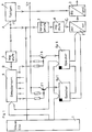
- the program run is controlled by a control device 1 which, depending on the intended use of the text generator, contains various monitoring and control devices, for example a microprocessor and a memory address counter.
- the announcement texts to be delivered in the telephone line which can be composed of individual specified text parts, are digitized according to the known principle of delta modulation and stored in the read-only memories Sp1 to Sp6 (e.g. ROM / EPROM). Texts or parts of text are output in such a way that the control device 1, controlled by the clock generator 4, releases the contents of one memory after the other and feeds them to a digital-to-analog converter 3 via a parallel-serial converter 2.
- the read-only memories Sp1 to Sp6 are constructed in a known manner in byte-wise organization.
- the supply voltage for the read-only memories Sp1 to Sp6 are supplied from the point U +, which is connected to a telephone line in a manner not specifically shown. To ensure that as little current as possible is drawn from the telephone line, the supply voltage is supplied to the memories in a clocked manner.
- a pulse stage 5 is driven by the clock generator 4 with the frequency f1 of the address pulses, which in turn clocks a decoding device 6, to which the control device 1 supplies the address signals.
- the decoding device 6 has a plurality of outputs, each of which is assigned to one of the memories Sp1 to Sp6.
- Each of these outputs of the decoding device 6 is connected to the base of a switching transistor T1 to T6, the collector of which is connected to the supply voltage input of the memory Sp1 to Sp6 assigned to it.
- the emitters of the switching transistors T1 to T6 are connected to the voltage source U +.
- the clock generator 4 gives rectangular pulses with the frequency f1 of, for example, 4 KHz or a pulse width of 250 / ls.
- the pulse shape occurring at A in FIG. 1 is shown under A in FIG. 1.
- Pulse stage 5 delivers six pulses at point B to the decoding device, as shown under B in FIG.
- the pulses have a width of 5u.s and are undelayed compared to the clock pulses A.
- the pulse stage 8 emits pulses to the parallel-serial converter 2 acting as a readout device at point C, as shown under C in FIG. These pulses have a width of 3 1i s and are delayed by 1 ⁇ s compared to the clock pulse.
- the supply voltages are thus controlled by the decoding device 6 via the switching transistors T1 to T6 and fed to the memories Sp1 to Sp6 each clocked in pulses of 5 ⁇ s duration. Each memory is thus switched on for a period of 5 / ls. During this switch-on time a readout pulse of 3 ⁇ s duration is applied, whereby, as shown in FIG.
- the delay of the readout pulse is such that the memory is switched on safely during the readout and is switched off again shortly after the readout. Since the supply voltage is only present for the period of 5 ⁇ s during the period of an address cycle of 250 / ls, the average current flowing through a memory is reduced by a factor of 50. This means that, for example, a current reduction from 100 mA to 2 mA or a reduction in the energy taken from the telephone line from, for example, 0.5 W to 10 mW is possible.
- FIG. 3 shows how an answering machine with an electronic text transmitter according to FIG. 1 can be connected to a telephone line.
- the answering machine 9 can be constructed as described, for example, in EP-A-75 854 (publication date Aug. 18, 1982). With such an answering machine, it is possible to deliver announcement texts in the telephone line, in which, for example, a time is communicated from which the caller can see when the user can be reached again.
- the user specifies the digits of the time to be inserted into the text parts according to a predetermined program at preselection switches S3.
- the number “14” is predetermined at the preselection switch S3.
- the answering machine can then, for example, hand it over to the telephone line after switching on the text "Hello, this is an answering machine, please call again at 2:00 p.m.”.
- the answering machine 9 with its supply voltage inputs + UB and -UB can be connected via a bridge G2 to the telephone line “ab” via the relay contact p.
- the NF output of the answering machine 9 can be connected to the telephone line “from” via the capacitor C4 and the bridge G2.
- a call evaluation circuit 10 can also be connected to the telephone line “from”, by means of which the answering machine 9 can be switched on and off in the manner described in more detail below.
- a telephone 12 is connected to the telephone line “from”.
- the switch S1 When the switch S1 is actuated, the call voltage reaches the rectifier bridge G1 via the capacitor C1 and the resistor R1.
- the Direct current flowing via the Zener diode Z1 and a further diode D1 charges the capacitor C2, voltage stabilization being achieved via the further Zener diode Z2.
- a DC voltage monitor 11 When a certain voltage threshold is reached, a DC voltage monitor 11 generates a directional pulse, which is supplied via an OR-GATE 0 to a relay connection stage AS containing a counter and sets the counter to 0.
- the second incoming call signal arrives, part of the call voltage goes directly to the relay connection stage AS via the resistor R2 and the capacitor C3 and sets the counter one step further.
- the bistable relay P is set from the relay connection stage AS during a subsequent call signal and thus the rectifier bridge G2 is connected to the telephone line "ab" via the contact p.
- a direct current then flows through the inductor L, regardless of polarity, and the supply voltage to the answering machine 9 is stabilized at the points -UB and + UB by the zener diode Z3. This is switched on and the preprogrammed announcement text is, for example, sent twice from the NF output to the telephone line "ab".
- the answering machine 9 gives a signal via an optocoupler OK and the OR gate O to the relay switch-on stage AS, which switches the bistable relay P back to the rest position, which has the consequence that now via the contact p Instead of the answering machine 9, the telephone set 12 is again connected to the telephone line “from”.
- the signal emitted by the answering machine 9 via the optocoupler OK passes through the resistor R3 to the base of a switching transistor T7, which then switches on and discharges the capacitor C2. Now the initial conditions have been restored and the call evaluation circuit 10 is ready to switch on the answering machine 9, if necessary, in response to the next incoming call signal.
- the answering machine can be reset by hand, so that the user can switch off the answering machine at any time even while the saying is in progress and take the call directly on the telephone set 12.
- An LED LD on the answering machine 9 indicates that the answering machine is in operation.
Landscapes
- Engineering & Computer Science (AREA)
- Signal Processing (AREA)
- Telephonic Communication Services (AREA)
- Telephone Function (AREA)
- Devices For Supply Of Signal Current (AREA)
- Financial Or Insurance-Related Operations Such As Payment And Settlement (AREA)
- Mobile Radio Communication Systems (AREA)
Claims (7)
Priority Applications (1)
| Application Number | Priority Date | Filing Date | Title |
|---|---|---|---|
| AT82102603T ATE7442T1 (de) | 1981-05-14 | 1982-03-27 | An eine fernsprechleitung angeschlossener elektronischer textgeber. |
Applications Claiming Priority (2)
| Application Number | Priority Date | Filing Date | Title |
|---|---|---|---|
| DE3119226 | 1981-05-14 | ||
| DE3119226A DE3119226C2 (de) | 1981-05-14 | 1981-05-14 | "An eine Fernsprechleitung angeschlossener elektronischer Textgeber" |
Publications (2)
| Publication Number | Publication Date |
|---|---|
| EP0065097A1 EP0065097A1 (fr) | 1982-11-24 |
| EP0065097B1 true EP0065097B1 (fr) | 1984-05-09 |
Family
ID=6132329
Family Applications (1)
| Application Number | Title | Priority Date | Filing Date |
|---|---|---|---|
| EP82102603A Expired EP0065097B1 (fr) | 1981-05-14 | 1982-03-27 | Générateur électronique de messages raccordé à une ligne téléphonique |
Country Status (3)
| Country | Link |
|---|---|
| EP (1) | EP0065097B1 (fr) |
| AT (1) | ATE7442T1 (fr) |
| DE (2) | DE3119226C2 (fr) |
Families Citing this family (11)
| Publication number | Priority date | Publication date | Assignee | Title |
|---|---|---|---|---|
| DE3214249C1 (de) * | 1982-04-17 | 1990-10-04 | Neumann Elektronik GmbH, 4330 Mülheim | Elektronischer Textgeber zur Abgabe und/oder Aufnahme von Texten ueber eine Fernsprechleitung |
| US4716582A (en) * | 1983-04-27 | 1987-12-29 | Phonetics, Inc. | Digital and synthesized speech alarm system |
| US4558181A (en) * | 1983-04-27 | 1985-12-10 | Phonetics, Inc. | Portable device for monitoring local area |
| DE3324517A1 (de) * | 1983-07-07 | 1985-01-17 | ANT Nachrichtentechnik GmbH, 7150 Backnang | Notrufsystem |
| DE3337699A1 (de) * | 1983-10-17 | 1985-04-25 | Siemens AG, 1000 Berlin und 8000 München | Schaltungsanordnung fuer eine rufauswertung |
| DE3540301A1 (de) * | 1985-11-13 | 1987-05-21 | Telemaster Gmbh | Automatischer rufnummergeber fuer fernsprecheinrichtungen |
| DE3604491A1 (de) * | 1986-02-13 | 1987-08-20 | Gaertner Karl Telegaertner | Vorrichtung mit einem bistabilen relais |
| DE3701919C1 (de) * | 1987-01-23 | 1988-07-14 | Neumann Elektronik Gmbh | Verfahren zur Reduzierung der Energieaufnahme einer Fernsprecheinrichtung,deren Versorgung mit elektrischer Energie ueber die Fernsprechleitung erfolgt,sowie Einrichtung zur Druchfuehrung des Verfahrens |
| DE4037514A1 (de) * | 1990-11-26 | 1992-05-27 | Grundig Emv | Teilnehmerendeinrichtung mit verbesserter sprachqualitaet gespeicherter ansagen |
| DE4405897C2 (de) * | 1994-02-19 | 1997-01-16 | Deutsche Telephonwerk Kabel | Schaltungsanordnung zur Rettung von Daten bei Netzspannungsausfall für Anrufbeantworter mit digitaler Sprachspeicherung in Kommunikations-Endgeräten |
| AUPN913196A0 (en) * | 1996-04-04 | 1996-05-02 | Miva Corporation Pty Limited | A recorded voice announcement device |
Family Cites Families (6)
| Publication number | Priority date | Publication date | Assignee | Title |
|---|---|---|---|---|
| US4049915A (en) * | 1975-06-20 | 1977-09-20 | Gte Automatic Electric Laboratories Incorporated | Remote access for centrally located answering and recording equipment |
| DE2853355A1 (de) * | 1978-12-11 | 1980-06-12 | Elektromechanik Aach Gmbh | Anrufbeantworter mit anordnung zur abgabe eines ansagetextes in die fernsprechleitung und gespraechs-aufzeichnungsanordnung |
| DE2854516B1 (de) * | 1978-12-16 | 1980-03-20 | Deutsche Fernsprecher Gmbh | Fernsprechapparat mit Anrufbeantworter |
| DE2854401C2 (de) * | 1978-12-16 | 1983-04-28 | Deutsche Fernsprecher Gesellschaft Mbh Marburg, 3550 Marburg | Anrufbeantworter |
| DE2931254A1 (de) * | 1979-07-30 | 1981-02-19 | Elmeg | Vorrichtung zur automatischen anrufbeantwortung |
| US4371751A (en) * | 1980-04-07 | 1983-02-01 | Newart Electronic Sciences, Inc. | Automatic telephonic user emergency message transmitting apparatus |
-
1981
- 1981-05-14 DE DE3119226A patent/DE3119226C2/de not_active Expired
-
1982
- 1982-03-27 EP EP82102603A patent/EP0065097B1/fr not_active Expired
- 1982-03-27 DE DE8282102603T patent/DE3260143D1/de not_active Expired
- 1982-03-27 AT AT82102603T patent/ATE7442T1/de not_active IP Right Cessation
Non-Patent Citations (1)
| Title |
|---|
| INTERFACE AGE, Band 5, Nr. 4, April 1980, Seiten 108-112, Cerritos, USA J. MacDOUGALL. "Powered down bipolar PROMs - A "cool" operating system" Seite 108,rechte Spalte, Zeile 7 - Seite 109, linke Spalte, Zeile 32; Figuren 1,2 * |
Also Published As
| Publication number | Publication date |
|---|---|
| DE3119226C2 (de) | 1983-04-28 |
| ATE7442T1 (de) | 1984-05-15 |
| EP0065097A1 (fr) | 1982-11-24 |
| DE3260143D1 (en) | 1984-06-14 |
| DE3119226A1 (de) | 1982-12-09 |
Similar Documents
| Publication | Publication Date | Title |
|---|---|---|
| EP0261319B1 (fr) | Disposition de circuit pour produire une tension alternative | |
| EP0065097B1 (fr) | Générateur électronique de messages raccordé à une ligne téléphonique | |
| EP0393233B1 (fr) | Système de transmission de signaux | |
| DE2701184A1 (de) | Schaltungsanordnung zur uebertragung von messwertsignalen | |
| EP0863637A2 (fr) | Equipement de communication avec bus optique et procédé de commande du fonctionnement de cet equiprment | |
| DE3329049A1 (de) | Datenuebertragungssystem | |
| EP0322698A1 (fr) | Méthode pour la transmission d'informations | |
| DE2533354B2 (de) | Einrichtung zum Übertragen von Steuerbefehlen in einem Brandschutzsystem | |
| DE1441404A1 (de) | Alarmanlage | |
| DE19705365A1 (de) | Vorrichtung zur zeitmultiplexen Übertragung von Informationen | |
| EP0035277A1 (fr) | Système de transmission séquentiel pour le branchement sans adresse de plusieurs abonnés à un central | |
| DE3214249C1 (de) | Elektronischer Textgeber zur Abgabe und/oder Aufnahme von Texten ueber eine Fernsprechleitung | |
| DE3424294A1 (de) | Abfrageeinrichtung zur identifikation der stellung von schaltern | |
| DE2931436C2 (de) | Schaltungsanordnung zum Überwachen einer Eingangsspannung | |
| DE2931435C2 (de) | Schaltungsanordnung zum Anschalten eines Modems an eine Fernsprechleitung | |
| DE3204429A1 (de) | Schaltungsanordnung zur geregelten spannungsversorgung von ferngespeisten endeinrichtungen in fernmelde-insbesondere fernsprechanlagen | |
| EP0362797B2 (fr) | Procédé pour un fonctionnement économique en énergie de détecteurs de danger dans un dispositif de détection de danger | |
| DE19918893B4 (de) | Kommunikationssystem, insbesondere Hausanlage | |
| DE2949513C2 (de) | Notrufanlage | |
| EP0450119A1 (fr) | Dispositif pour raccorder des éléments additionnels à une ligne servant à la surveillance et déjà existante | |
| DE3604753A1 (de) | Schaltungsanordnung fuer einen elektronischen rundsteuerempfaenger | |
| AT315952B (de) | Empfänger für tonfrequente Netzüberlagerungsfernsteueranlagen und Rundsteueranlagen mit solchen Empfängern | |
| DE1562230C3 (de) | Schaltungsanordnung für Fernmeldevermittlungsanlagen, insbesondere Fernsprechvermittlungsanlagen, in denen Verbindungen auf Grund von Anschalteanreizen hergestellt werden | |
| DE3119080A1 (de) | Automatischer anrufbeantworter | |
| EP0305680B1 (fr) | Commande d'un ordinateur principal par un poste de travail éloigné |
Legal Events
| Date | Code | Title | Description |
|---|---|---|---|
| PUAI | Public reference made under article 153(3) epc to a published international application that has entered the european phase |
Free format text: ORIGINAL CODE: 0009012 |
|
| AK | Designated contracting states |
Designated state(s): AT BE CH DE FR GB IT LU NL SE |
|
| 17P | Request for examination filed |
Effective date: 19820922 |
|
| ITF | It: translation for a ep patent filed |
Owner name: STUDIO INGG. FISCHETTI & WEBER |
|
| GRAA | (expected) grant |
Free format text: ORIGINAL CODE: 0009210 |
|
| STAA | Information on the status of an ep patent application or granted ep patent |
Free format text: STATUS: THE PATENT HAS BEEN GRANTED |
|
| AK | Designated contracting states |
Designated state(s): AT BE CH DE FR GB IT LI LU NL SE |
|
| REF | Corresponds to: |
Ref document number: 7442 Country of ref document: AT Date of ref document: 19840515 Kind code of ref document: T |
|
| REF | Corresponds to: |
Ref document number: 3260143 Country of ref document: DE Date of ref document: 19840614 |
|
| ET | Fr: translation filed | ||
| PLBE | No opposition filed within time limit |
Free format text: ORIGINAL CODE: 0009261 |
|
| PG25 | Lapsed in a contracting state [announced via postgrant information from national office to epo] |
Ref country code: LU Free format text: LAPSE BECAUSE OF NON-PAYMENT OF DUE FEES Effective date: 19850331 |
|
| 26N | No opposition filed | ||
| PGFP | Annual fee paid to national office [announced via postgrant information from national office to epo] |
Ref country code: AT Payment date: 19870313 Year of fee payment: 6 |
|
| PGFP | Annual fee paid to national office [announced via postgrant information from national office to epo] |
Ref country code: NL Payment date: 19870331 Year of fee payment: 6 |
|
| PG25 | Lapsed in a contracting state [announced via postgrant information from national office to epo] |
Ref country code: AT Effective date: 19880327 |
|
| PG25 | Lapsed in a contracting state [announced via postgrant information from national office to epo] |
Ref country code: SE Effective date: 19880328 |
|
| PG25 | Lapsed in a contracting state [announced via postgrant information from national office to epo] |
Ref country code: LI Effective date: 19880331 Ref country code: CH Effective date: 19880331 |
|
| BERE | Be: lapsed |
Owner name: NEUMANN ELEKTRONIK G.M.B.H. Effective date: 19880331 |
|
| PG25 | Lapsed in a contracting state [announced via postgrant information from national office to epo] |
Ref country code: NL Effective date: 19881001 |
|
| NLV4 | Nl: lapsed or anulled due to non-payment of the annual fee | ||
| PG25 | Lapsed in a contracting state [announced via postgrant information from national office to epo] |
Ref country code: GB Free format text: LAPSE BECAUSE OF NON-PAYMENT OF DUE FEES Effective date: 19881121 |
|
| GBPC | Gb: european patent ceased through non-payment of renewal fee | ||
| PG25 | Lapsed in a contracting state [announced via postgrant information from national office to epo] |
Ref country code: FR Free format text: LAPSE BECAUSE OF NON-PAYMENT OF DUE FEES Effective date: 19881130 |
|
| REG | Reference to a national code |
Ref country code: CH Ref legal event code: PL |
|
| REG | Reference to a national code |
Ref country code: FR Ref legal event code: ST |
|
| PG25 | Lapsed in a contracting state [announced via postgrant information from national office to epo] |
Ref country code: BE Effective date: 19890331 |
|
| PGFP | Annual fee paid to national office [announced via postgrant information from national office to epo] |
Ref country code: DE Payment date: 19940331 Year of fee payment: 13 |
|
| EUG | Se: european patent has lapsed |
Ref document number: 82102603.6 Effective date: 19881206 |
|
| PG25 | Lapsed in a contracting state [announced via postgrant information from national office to epo] |
Ref country code: DE Effective date: 19951201 |