EP0065097B1 - Electronic message generator connected to a telephone line - Google Patents
Electronic message generator connected to a telephone line Download PDFInfo
- Publication number
- EP0065097B1 EP0065097B1 EP82102603A EP82102603A EP0065097B1 EP 0065097 B1 EP0065097 B1 EP 0065097B1 EP 82102603 A EP82102603 A EP 82102603A EP 82102603 A EP82102603 A EP 82102603A EP 0065097 B1 EP0065097 B1 EP 0065097B1
- Authority
- EP
- European Patent Office
- Prior art keywords
- telephone line
- read
- value memories
- call
- pulses
- Prior art date
- Legal status (The legal status is an assumption and is not a legal conclusion. Google has not performed a legal analysis and makes no representation as to the accuracy of the status listed.)
- Expired
Links
Images


Classifications
-
- H—ELECTRICITY
- H04—ELECTRIC COMMUNICATION TECHNIQUE
- H04M—TELEPHONIC COMMUNICATION
- H04M19/00—Current supply arrangements for telephone systems
- H04M19/08—Current supply arrangements for telephone systems with current supply sources at the substations
-
- H—ELECTRICITY
- H04—ELECTRIC COMMUNICATION TECHNIQUE
- H04M—TELEPHONIC COMMUNICATION
- H04M1/00—Substation equipment, e.g. for use by subscribers
- H04M1/64—Automatic arrangements for answering calls; Automatic arrangements for recording messages for absent subscribers; Arrangements for recording conversations
- H04M1/642—Automatic arrangements for answering calls; Automatic arrangements for recording messages for absent subscribers; Arrangements for recording conversations storing speech in digital form
-
- H—ELECTRICITY
- H04—ELECTRIC COMMUNICATION TECHNIQUE
- H04M—TELEPHONIC COMMUNICATION
- H04M11/00—Telephonic communication systems specially adapted for combination with other electrical systems
- H04M11/04—Telephonic communication systems specially adapted for combination with other electrical systems with alarm systems, e.g. fire, police or burglar alarm systems
- H04M11/045—Telephonic communication systems specially adapted for combination with other electrical systems with alarm systems, e.g. fire, police or burglar alarm systems using recorded signals, e.g. speech
Definitions
- the invention relates to an electronic text generator connected to a telephone line for the delivery of predefined announcement texts into the telephone line, the announcement texts being stored in digital form in read-only memories, to which address pulses and readout pulses are supplied via a control device with a predefined clock frequency and which are followed by a digital-to-analog converter is.
- Such text generators are known per se, for example from DE-B-2854516 or DE-A-2931 254. They have been used, for example, for voice output via the telephone network, for example in order development in retail or also in answering machines. They can be controlled from a data processing system, for example a microcomputer.
- the text to be stored in the read-only memories can be converted into digital voice data in accordance with the known method of delta modulation.
- the digital-to-analog converter downstream of the read-only memory then contains a delta demodulator.
- the object on which the invention is based is to create an electronic text generator of the type specified above, which is connected to a telephone line and which is independent of an additional power supply at the installation site, ie does not require its own connection to the mains voltage or another voltage source.
- Such independence of the text generator from an additional power supply is of particular importance if the text generator is, for example, part of an answering machine or an emergency call device, that is to say a device which is to remain operational even if, for example, there is a power failure in the local network.
- the read-only memories are supplied with power via the telephone line, the supply voltages being supplied to the read-only memories at the clock frequency of the address pulses in individual pulses in such a temporal position and width that the supply voltage at each read-only memory is at a predetermined time before arrival of the readout pulse is present and remains switched on for at least the entire duration of the readout pulse.
- the electronic text generator according to the invention is part of an automatic answering machine, the entire power supply for this answering machine being carried out via the telephone line, so that the answering machine and the telephone set itself remain active even if there is a local power failure.
- the electronic text generator according to the invention is part of an automatic emergency call device, for example in an elevator.
- An emergency call device is obtained in this way, in which the otherwise usual identification display, for example by impulses, is replaced by an automatic identification announcement.
- the device is very insensitive to interference and there is no need for an additional electronic device to be present at the interrogation point, rather a simple telephone set is sufficient.
- the identification announcements are easy to store at the interrogation point (tape) and the device remains functional even in the event of a power failure at the sending point.
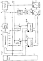
- the program run is controlled by a control device 1 which, depending on the intended use of the text generator, contains various monitoring and control devices, for example a microprocessor and a memory address counter.
- the announcement texts to be delivered in the telephone line which can be composed of individual specified text parts, are digitized according to the known principle of delta modulation and stored in the read-only memories Sp1 to Sp6 (e.g. ROM / EPROM). Texts or parts of text are output in such a way that the control device 1, controlled by the clock generator 4, releases the contents of one memory after the other and feeds them to a digital-to-analog converter 3 via a parallel-serial converter 2.
- the read-only memories Sp1 to Sp6 are constructed in a known manner in byte-wise organization.
- the supply voltage for the read-only memories Sp1 to Sp6 are supplied from the point U +, which is connected to a telephone line in a manner not specifically shown. To ensure that as little current as possible is drawn from the telephone line, the supply voltage is supplied to the memories in a clocked manner.
- a pulse stage 5 is driven by the clock generator 4 with the frequency f1 of the address pulses, which in turn clocks a decoding device 6, to which the control device 1 supplies the address signals.
- the decoding device 6 has a plurality of outputs, each of which is assigned to one of the memories Sp1 to Sp6.
- Each of these outputs of the decoding device 6 is connected to the base of a switching transistor T1 to T6, the collector of which is connected to the supply voltage input of the memory Sp1 to Sp6 assigned to it.
- the emitters of the switching transistors T1 to T6 are connected to the voltage source U +.
- the clock generator 4 gives rectangular pulses with the frequency f1 of, for example, 4 KHz or a pulse width of 250 / ls.
- the pulse shape occurring at A in FIG. 1 is shown under A in FIG. 1.
- Pulse stage 5 delivers six pulses at point B to the decoding device, as shown under B in FIG.
- the pulses have a width of 5u.s and are undelayed compared to the clock pulses A.
- the pulse stage 8 emits pulses to the parallel-serial converter 2 acting as a readout device at point C, as shown under C in FIG. These pulses have a width of 3 1i s and are delayed by 1 ⁇ s compared to the clock pulse.
- the supply voltages are thus controlled by the decoding device 6 via the switching transistors T1 to T6 and fed to the memories Sp1 to Sp6 each clocked in pulses of 5 ⁇ s duration. Each memory is thus switched on for a period of 5 / ls. During this switch-on time a readout pulse of 3 ⁇ s duration is applied, whereby, as shown in FIG.
- the delay of the readout pulse is such that the memory is switched on safely during the readout and is switched off again shortly after the readout. Since the supply voltage is only present for the period of 5 ⁇ s during the period of an address cycle of 250 / ls, the average current flowing through a memory is reduced by a factor of 50. This means that, for example, a current reduction from 100 mA to 2 mA or a reduction in the energy taken from the telephone line from, for example, 0.5 W to 10 mW is possible.
- FIG. 3 shows how an answering machine with an electronic text transmitter according to FIG. 1 can be connected to a telephone line.
- the answering machine 9 can be constructed as described, for example, in EP-A-75 854 (publication date Aug. 18, 1982). With such an answering machine, it is possible to deliver announcement texts in the telephone line, in which, for example, a time is communicated from which the caller can see when the user can be reached again.
- the user specifies the digits of the time to be inserted into the text parts according to a predetermined program at preselection switches S3.
- the number “14” is predetermined at the preselection switch S3.
- the answering machine can then, for example, hand it over to the telephone line after switching on the text "Hello, this is an answering machine, please call again at 2:00 p.m.”.
- the answering machine 9 with its supply voltage inputs + UB and -UB can be connected via a bridge G2 to the telephone line “ab” via the relay contact p.
- the NF output of the answering machine 9 can be connected to the telephone line “from” via the capacitor C4 and the bridge G2.
- a call evaluation circuit 10 can also be connected to the telephone line “from”, by means of which the answering machine 9 can be switched on and off in the manner described in more detail below.
- a telephone 12 is connected to the telephone line “from”.
- the switch S1 When the switch S1 is actuated, the call voltage reaches the rectifier bridge G1 via the capacitor C1 and the resistor R1.
- the Direct current flowing via the Zener diode Z1 and a further diode D1 charges the capacitor C2, voltage stabilization being achieved via the further Zener diode Z2.
- a DC voltage monitor 11 When a certain voltage threshold is reached, a DC voltage monitor 11 generates a directional pulse, which is supplied via an OR-GATE 0 to a relay connection stage AS containing a counter and sets the counter to 0.
- the second incoming call signal arrives, part of the call voltage goes directly to the relay connection stage AS via the resistor R2 and the capacitor C3 and sets the counter one step further.
- the bistable relay P is set from the relay connection stage AS during a subsequent call signal and thus the rectifier bridge G2 is connected to the telephone line "ab" via the contact p.
- a direct current then flows through the inductor L, regardless of polarity, and the supply voltage to the answering machine 9 is stabilized at the points -UB and + UB by the zener diode Z3. This is switched on and the preprogrammed announcement text is, for example, sent twice from the NF output to the telephone line "ab".
- the answering machine 9 gives a signal via an optocoupler OK and the OR gate O to the relay switch-on stage AS, which switches the bistable relay P back to the rest position, which has the consequence that now via the contact p Instead of the answering machine 9, the telephone set 12 is again connected to the telephone line “from”.
- the signal emitted by the answering machine 9 via the optocoupler OK passes through the resistor R3 to the base of a switching transistor T7, which then switches on and discharges the capacitor C2. Now the initial conditions have been restored and the call evaluation circuit 10 is ready to switch on the answering machine 9, if necessary, in response to the next incoming call signal.
- the answering machine can be reset by hand, so that the user can switch off the answering machine at any time even while the saying is in progress and take the call directly on the telephone set 12.
- An LED LD on the answering machine 9 indicates that the answering machine is in operation.
Landscapes
- Engineering & Computer Science (AREA)
- Signal Processing (AREA)
- Telephonic Communication Services (AREA)
- Telephone Function (AREA)
- Devices For Supply Of Signal Current (AREA)
- Financial Or Insurance-Related Operations Such As Payment And Settlement (AREA)
- Mobile Radio Communication Systems (AREA)
Abstract
Description
Gegenstand der Erfindung ist ein an eine Fernsprechleitung angeschlossener elektronischer Textgeber zur Abgabe vorgegebener Ansagetexte in die Fernsprechleitung, wobei die Ansagetexte in digitaler Form in Festwertspeichern gespeichert sind, denen über eine Steuereinrichtung mit einer vorgegebenen Taktfrequenz Adressenimpulse sowie Ausleseimpulse zugeführt werden und denen ein Digital-Analogwandler nachgeschaltet ist.The invention relates to an electronic text generator connected to a telephone line for the delivery of predefined announcement texts into the telephone line, the announcement texts being stored in digital form in read-only memories, to which address pulses and readout pulses are supplied via a control device with a predefined clock frequency and which are followed by a digital-to-analog converter is.
Derartige Textgeber sind an sich bekannt, beispielsweise aus der DE-B-2854516 oder DE-A-2931 254. Sie sind beispielsweise zur Sprachausgabe über das Telefonnetz, beispielsweise bei derAuftragsentwicklung im Handel oder auch bei Anrufbeantwortern, eingesetzt worden. Ihre Steuerung kann von einer Datenverarbeitungsanlage, beispielsweise einem Mikrocomputer, aus erfolgen.Such text generators are known per se, for example from DE-B-2854516 or DE-A-2931 254. They have been used, for example, for voice output via the telephone network, for example in order development in retail or also in answering machines. They can be controlled from a data processing system, for example a microcomputer.
Die Umformung der in den Festwertspeichern zu speichernden Texte in digitale Sprachdaten kann dabei gemäss dem bekannten Verfahren der Delta-Modulation erfolgen. Der dem Festwertspeicher nachgeschaltete Digital-Analogwandler enthält dann einen Delta-Demodulator.The text to be stored in the read-only memories can be converted into digital voice data in accordance with the known method of delta modulation. The digital-to-analog converter downstream of the read-only memory then contains a delta demodulator.
Die der Erfindung zugrunde liegende Aufgabe besteht darin, einen an eine Fernsprechleitung angeschlossenen, elektronischen Textgeber der oben angegebenen Art zu schaffen, der am Aufstellungsort unabhängig von einer zusätzlichen Stromversorgung ist, also keinen eigenen Anschluss an die Netzspannung oder eine andere Spannungsquelle benötigt. Eine derartige Unabhängigkeit des Textgebers von einer zusätzlichen Stromversorgung ist von besonderer Bedeutung, wenn der Textgeber beispielsweise Teil eines Anrufbeantworters oder einer Notrufeinrichtung ist, also einem Gerät, das auch dann betriebsbereit bleiben soll, wenn beispielsweise ein Spannungsausfall im örtlichen Netz vorliegt.The object on which the invention is based is to create an electronic text generator of the type specified above, which is connected to a telephone line and which is independent of an additional power supply at the installation site, ie does not require its own connection to the mains voltage or another voltage source. Such independence of the text generator from an additional power supply is of particular importance if the text generator is, for example, part of an answering machine or an emergency call device, that is to say a device which is to remain operational even if, for example, there is a power failure in the local network.
Die Lösung dieser Aufgabe erfolgt erfindungsgemäss dadurch, dass die Stromversorgung der Festwertspeicher über die Fernsprechleitung erfolgt, wobei die Speisespannungen den Festwertspeichern mit der Taktfrequenz der Adressenimpulse in Einzelimpulsen solcher zeitlichen Lage und Breite zugeführt werden, dass an jedem Festwertspeicher die Speisespannung zu einem vorgegebenen Zeitpunkt vor Eintreffen des Ausleseimpulses anliegt und mindestens während der gesamten Dauer des Ausleseimpulses eingeschaltet bleibt.This object is achieved according to the invention in that the read-only memories are supplied with power via the telephone line, the supply voltages being supplied to the read-only memories at the clock frequency of the address pulses in individual pulses in such a temporal position and width that the supply voltage at each read-only memory is at a predetermined time before arrival of the readout pulse is present and remains switched on for at least the entire duration of the readout pulse.
Bei der Stromversorgung der im elektronischen Textgeber angeordneten Festwertspeicher muss berücksichtigt werden, dass über die Festwertspeicher, solange die Speisespannung von 5V angelegt ist, ein relativ hoher Strom von 100mA fliesst. Da einer Fernspreichleitung im allgemeinen nur wenig elektrische Energie entnommen werden darf, ist es nicht ohne weiteres möglich, die Speisespannung für die Festwertspeicher ständig der Fernsprechleitung zu entnehmen. Der Grundgedanke der Erfindung besteht daher darin, jeden Festwertspeicher nur solange mit der Speisespannung zu beaufschlagen, wie dies unbedingt erforderlich ist. Dies führt gemäss den weiteren Merkmalen aus dem kennzeichnenden Teil des Patentanspruchs 1 dazu, dass erfindungsgemäss die Speisespannung den Festwertspeichern in einzelnen Impulsen zugeführt werden, die nur während des Zeitraums anliegen, in dem der betreffende Speicher ausgelesen wird. Auf diese Weise wird nur für die Zeit Strom verbraucht, die benötigt wird, um ein Byte auszulesen. Dadurch ist es möglich, den im Durchschnitt über die Festwertspeicher fliessenden Strom auf einen Bruchteil des Stromes zu verringern, der fliessen würde, wenn die Speicher ständig oder auch nur während des ganzen Auslesevorganges ständig eingeschaltet wären.When powering the read-only memories in the electronic text generator, it must be taken into account that a relatively high current of 100 mA flows through the read-only memories as long as the supply voltage of 5V is applied. Since in general only a little electrical energy may be taken from a remote storage line, it is not readily possible to continuously take the supply voltage for the read-only memories from the telephone line. The basic idea of the invention is therefore to only supply each read-only memory with the supply voltage for as long as is absolutely necessary. According to the further features from the characterizing part of
Verschiedene vorteilhafte Ausführungsformen des erfindungsgemässen Textgebers sind möglich und Gegenstand der Unteransprüche 2 bis 6.Various advantageous embodiments of the text generator according to the invention are possible and the subject matter of
So ist beispielsweise bei einer besonders vorteilhaften Ausführungsform der erfindungsgemässe elektronische Textgeber Teil eines automatischen Anrufbeantworters, wobei die gesamte Stromversorgung dieses Anrufbeantworters über die Fernsprechleitung erfolgt, so dass der Anrufbeantworter wie der Fernsprechapparat selbst in Tätigkeit bleibt, auch wenn ein örtlicher Netzausfall vorliegt.For example, in a particularly advantageous embodiment, the electronic text generator according to the invention is part of an automatic answering machine, the entire power supply for this answering machine being carried out via the telephone line, so that the answering machine and the telephone set itself remain active even if there is a local power failure.
Bei einer weiteren, in Patentanspruch 6 beschriebenen Ausführungsform ist der erfindungsgemässe elektronische Textgeber Teil einer automatischen Notrufeinrichtung, beispielsweise in einem Aufzug. Man erhält auf diese Weise eine Notrufeinrichtung, bei der die sonst übliche Kennungsanzeige, beispielsweise durch Impulse, durch eine automatische Kennungsansage ersetzt wird. Auf diese Weise wird die Einrichtung sehr störungsunempfindlich und es braucht an der Abfragestelle keine zusätzliche elektronische Einrichtung vorhanden zu sein, es genügt vielmehr ein einfacher Telefonapparat. Die Kennungsansagen sind an der Abfragestelle leicht speicherbar (Tonband) und die Einrichtung bleibt auch bei einem Netzausfall an der Sendestelle funktionsfähig.In a further embodiment described in
Im folgenden wird anhand der beigefügten Zeichnungen ein Ausführungsbeispiel des elektronischen Textgebers nach der Erfindung sowie seine Anwendungsmöglichkeit in einem Anrufbeantworter näher erläutert.In the following, an embodiment of the electronic text generator according to the invention and its application in an answering machine will be explained in more detail with reference to the accompanying drawings.
In den Zeichnungen zeigen:
- Fig. 1 in einem Prinzipschaltbild einen elektronischen Textgeber;
- Fig. 2 in einem zeitlichen Diagramm den einem Festwertspeicher des Textgebers nach Fig. 1 zugeführten Speisespannungs- und Ausleseimpuls;
- Fig. 3 in einem Prinzipschaltbild einen Anrufbeantworter mit einem Textgeber nach Fig. 1.
- 1 shows a basic circuit diagram of an electronic text generator;
- FIG. 2 shows in a time diagram the supply voltage and readout pulse supplied to a read-only memory of the text generator according to FIG. 1;
- 3 shows a block diagram of an answering machine with a text generator according to FIG. 1.
In Fig. 1 sind lediglich die für die Erfindung wesentlichen Teile eines elektronischen Textgebers in einem Blockschaltbild dargestellt.In Fig. 1, only the parts of an electronic text generator essential for the invention are shown in a block diagram.
Der Programmlauf wird von einer Steuereinrichtung 1 aus gesteuert, die je nach dem Verwendungszweck des Textgebers verschiedene Vorrichtungen zur Überwachung und Steuerung, beispielsweise einen Mikroprozessor sowie einen Speicher-Adressenzähler, enthält. Die in die Fernsprechleitung abzugebenden Ansagetexte, die sich aus einzelnen vorgegebenen Textteilen zusammensetzen können, sind nach dem bekannten Prinzip der Delta-Modulation digitalisiert und in den Festwertspeichern Sp1 bis Sp6 (z.B. ROM/EPROM) abgelegt. Die Ausgabe von Texten oder Textteilen erfolgt in der Weise, dass von der Steuereinrichtung 1 aus, gesteuert durch den Taktgenerator 4, der Inhalt eines Speichers nach dem anderen freigegeben und über einen Parallel-Seriell-Wandler 2 einem Digital-Analogwandler 3 zugeführt wird. Die Festwertspeicher Sp1 bis Sp6 sind in bekannter Weise in byteweiser Organsiation aufgebaut.The program run is controlled by a
An den Digital-Anlogwandler 3 sind in acht nicht eigens dargestellter Weise weitere Vorrichtungen, wie Filter und Verstärker, angeschlossen.Further devices, such as filters and amplifiers, are connected to the digital analog converter 3 in eight ways (not specifically shown).
Die Speisespannung für die Festwertspeicher Sp1 bis Sp6 werden vom Punkt U+ aus zugeführt, der in nicht eigens dargestellter Weise an eine Fernsprechleitung angeschlossen ist. Damit der Fernsprechleitung möglichst wenig Strom entnommen wird, wird die Speisespannung den Speichern getaktet zugeführt. Zu diesem Zweck wird vom Taktgenerator 4 aus mit der Frequenz f1 der Adressenimpulse eine Impulsstufe 5 angesteuert, die ihrerseits eine Dekodiervorrichtung 6 taktet, der von der Steuereinrichtung 1 aus die Adressensignale zugeführt werden. Die Dekodiervorrichtung 6 besitzt mehrere Ausgänge, von denen jeder einem der Speicher Sp1 bis Sp6 zugeordnet ist. Jeder dieser Ausgänge der Dekodiervorrichtung 6 ist mit der Basis eines Schalttransistors T1 bis T6 verbunden, dessen Kollektor mit dem Speisespannungseingang des ihm zugeordneten Speichers Sp1 bis Sp6 verbunden ist. Die Emitter der Schalttransistoren T1 bis T6 sind mit der Spannungsquelle U+ verbunden.The supply voltage for the read-only memories Sp1 to Sp6 are supplied from the point U +, which is connected to a telephone line in a manner not specifically shown. To ensure that as little current as possible is drawn from the telephone line, the supply voltage is supplied to the memories in a clocked manner. For this purpose, a
Der Parallel-Seriell-Wandler 2, über den die Auslesung der Speicher Sp1 bis Sp6 erfolgt, wird vom Taktgenerator 4 über eine Verzögerungsstufe 7 und eine Impulsstufe 8 mit der Frequenz f1 der Adressenimpulse angesteuert, während der Digital-Anlogwandler 3 vom Taktgenerator 4 aus mit der Frequenz f2 = 8x f1 angesteuert wird.The parallel-to-
Die Funktionsweise der Schaltung zur Zuführung der Speisespannungen wird im folgenden unterZuhilfenahme vom Fig. 2 beschrieben.The operation of the circuit for supplying the supply voltages is described below with the aid of FIG. 2.
Der Taktgenerator 4 gibt Rechteckimpulse mit der Frequenz f1 von beispielsweise 4 KHz bzw. einer Impulsbreite von 250/ls. Die in Fig. 1 bei A auftretende Impulsform ist in Fig. 1 unter A dargestellt. Die Impulsstufe 5 liefert am Punkt B an die Dekodiervorrichtung sechs Impulse, wie sie in Fig. 2 unter B dargestellt sind.The
Die Impulse besitzen eine Breite von 5u.s und sind gegenüber den Taktimpulsen A unverzögert. Die Impulsstufe 8 gibt an den als Ausleseeinrichtung fungierenden Paralell-Seriell-Wandler 2 am Punkt C Impulse ab, wie sie in Fig. 2 unter C dargestellt sind. Diese Impulse besitzen eine Breite von 31is und sind gegenüber dem Taktimpuls um 1µs verzögert. Die Speisespannungen werden also gesteuert von der Dekodiervorrichtung 6 über die Schalttransistoren T1 bis T6 den Speichern Sp1 bis Sp6 jeweils getaktet in Impulsen von 5µs Dauer zugeführt. Somit ist jeder Speicher für die Dauer von 5/ls eingeschaltet. Während dieser Einschaltzeit wird ein Ausleseimpuls von 3µs Dauer angelegt, wobei, wie in Fig. 2 dargestellt, die Verzögerung des Ausleseimpulses so ist, dass während des Auslesens der Speicher sicher eingeschaltet ist und kurz nach dem Auslesen wieder abgeschaltet wird. Da somit während des Zeitraumes eines Adressentaktes von 250/ls die Speisespannung nur während des Zeitraumes von 5µs anliegt, wird der mittlere Strom, der über einen Speicher fliesst, um den Faktor 50 verringert. Dies bedeutet, dass beispielsweise eine Stromverminderung von 100 mA auf 2 mA bzw. eine Verminderung der aus der Fernsprechleitung entnommenen Energie von beispielsweise 0,5 W auf 10 mW möglich ist.The pulses have a width of 5u.s and are undelayed compared to the clock pulses A. The pulse stage 8 emits pulses to the parallel-
In Fig. 3 ist dargestellt, in welcher Weise ein Anrufbeantworter mit einem elektronischen Textgeber nach Fig. 1 an eine Fernsprechleitung angeschlossen werden kann.FIG. 3 shows how an answering machine with an electronic text transmitter according to FIG. 1 can be connected to a telephone line.
Der im einzelnen nicht dargestellte Anrufbeantworter 9 kann dabei so aufgebaut sein, wie dies beispielsweise in der EP-A-75 854 (Veröffentlichungsdatum 18.8.82) beschrieben ist. Mit einem derartigen Anrufbeantworter ist es möglich, Ansagetexte in die Fernsprechleitung abzugeben, in denen beispielsweise eine Uhrzeit mitgeteilt wird, aus der der Anrufer ersehen kann, wann der Benutzer wieder erreichbar ist.The
Zu diesem Zweck gibt der Benutzer die in die Textteile gemäss einem vorgegebenen Programm einzufügenden Ziffern der Uhrzeit an Vorwahlschaltern S3 vor. In dem in Fig. 3 dargestellten Ausführungsbeispiel ist am Vorwahlschalter S3 die Zahl «14» vorgegeben. Aufgrund des eingestellten Programms kann der Anrufbeantworter dann beispielsweise nach seiner Einschaltung von Text «Guten Tag, hier spricht ein Anrufbeantworter, bitte rufen Sie um 14.00 Uhr wieder an» in die Fernsprechleitung abgeben.For this purpose, the user specifies the digits of the time to be inserted into the text parts according to a predetermined program at preselection switches S3. In the exemplary embodiment shown in FIG. 3, the number “14” is predetermined at the preselection switch S3. Based on the set program, the answering machine can then, for example, hand it over to the telephone line after switching on the text "Hello, this is an answering machine, please call again at 2:00 p.m.".
Der Anrufbeantworter 9 ist mit seinen Speisespannungseingängen +UB und -UB über eine Brücke G2 an die Fernsprechleitung «ab» über den Relaiskontakt p anschliessbar. Ebenso ist der NF-Ausgang des Anrufbeantworters 9 über den Kondensator C4 und die Brücke G2 an die Fernsprechleitung «ab» anschliessbar. Gleichfalls an die Fernsprechleitung «ab» anschliessbar ist eine Ruf-Auswerteschaltung 10, durch welche der Anrufbeantworter 9 in der im folgenden näher beschriebenen Weise ein- und abschaltbar ist.The
Im einzelnen ist bei der in Fig. 3 dagestellten Schaltung ein Telefon 12 an die Fernsprechleitung «ab» angeschlossen. Bei Betätigung des Schalters S1 gelangt bei einem Anruf die Rufspannung über den Kondensator C1 und den Widerstand R1 zur Gleichrichterbrücke G1. Der über die Zenerdiode Z1 und eine weitere Diode D1 fliessende Gleichstrom lädt den Kondensator C2 auf, wobei über die weitere Zenerdiode Z2 eine Spannungsstabilisation erreicht wird. Bei Erreichen einer bestimmten Spannungsschwelle erzeugt ein Gleichspannungswächter 11 einen Richtimpuls, der über ein ODER-GATTER 0 einer einen Zähler enthaltenden Relais-Anschaltstufe AS zugeführt wird und den Zähler auf O setzt. Beim zweiten ankommenden Rufsignal gelangt ein Teil der Rufspannung über den Widerstand R2 und den Kondensator C3 direkt auf die Relais-Anschaltstufe AS und setzt den Zähler eine Stufe weiter. Je nach der Voreinstellung des Zählers wird von der Relais-Anschaltstufe AS aus während eines folgenden Rufsignals das bistabile Relais P gesetzt und damit über den Kontakt p die Gleichrichterbrücke G2 an die Fernsprechleitung «ab» angeschlossen. Über diese Gleichstrombrücke G2 fliesst dann polungsunabhängig ein Gleichstrom durch die Drossel L, und an den Punkten -UB und +UB liegt stabilisiert durch die Zenerdiode Z3 die Speisespannung am Anrufbeantworter 9 an. Dieser ist dadurch eingeschaltet und der vorprogrammierte Ansagetext wird beispielsweise zweimal vom Ausgang NF aus auf die Fernsprechleitung «ab» gegeben. Nach dem Ende des Ansagetextes wird vom Anrufbeantworter 9 ein Signal über einen Optokoppler OK und das ODER-Gatter O auf die Relais-Anschaltstufe AS gegeben, die das bistabile Relais P zurück in die Ruhestellung schaltet, was zur Folge hat, dass nunmehr über den Kontakt p anstelle des Anrufbeantworters 9 wieder der Fernsprechapparat 12 mit der Fernsprechleitung «ab» verbunden ist. Das vom Anrufbeantworter 9 über den Optokoppler OK abgegebene Signal gelangt über den Widerstand R3 auf die Basis eines Schalttransistors T7, der daraufhin durchschaltet und den Kondensator C2 entlädt. Nun sind die Anfangsbedingungen wieder hergestellt und die Rufauswerteschaltung 10 ist bereit, auf das nächste ankommende Rufsignal hin gegebenenfalls den Anrufbeantworter 9 wiederum einzuschalten.In particular, in the circuit shown in FIG. 3, a
Mittels des am Anrufbeantworter 9 angeordneten Rückstellschalters S2 kann der Anrufbeantworter von Hand rückgestelltwerden, so dass der Benutzer jederzeit auch bei laufendem Spruch den Anrufbeantworter abschalten und den Anruf direkt am Fernsprechapparat 12 entgegennehmen kann.By means of the reset switch S2 arranged on the answering
Eine Leuchtdiode LD am Anrufbeantworter 9 zeigt an, dass der Anrufbeantworter in Betrieb ist.An LED LD on the answering
Claims (7)
Priority Applications (1)
| Application Number | Priority Date | Filing Date | Title |
|---|---|---|---|
| AT82102603T ATE7442T1 (en) | 1981-05-14 | 1982-03-27 | ELECTRONIC TEXT TRANSMITTER CONNECTED TO A TELEPHONE LINE. |
Applications Claiming Priority (2)
| Application Number | Priority Date | Filing Date | Title |
|---|---|---|---|
| DE3119226 | 1981-05-14 | ||
| DE3119226A DE3119226C2 (en) | 1981-05-14 | 1981-05-14 | "Electronic text generator connected to a telephone line" |
Publications (2)
| Publication Number | Publication Date |
|---|---|
| EP0065097A1 EP0065097A1 (en) | 1982-11-24 |
| EP0065097B1 true EP0065097B1 (en) | 1984-05-09 |
Family
ID=6132329
Family Applications (1)
| Application Number | Title | Priority Date | Filing Date |
|---|---|---|---|
| EP82102603A Expired EP0065097B1 (en) | 1981-05-14 | 1982-03-27 | Electronic message generator connected to a telephone line |
Country Status (3)
| Country | Link |
|---|---|
| EP (1) | EP0065097B1 (en) |
| AT (1) | ATE7442T1 (en) |
| DE (2) | DE3119226C2 (en) |
Families Citing this family (11)
| Publication number | Priority date | Publication date | Assignee | Title |
|---|---|---|---|---|
| DE3214249C1 (en) * | 1982-04-17 | 1990-10-04 | Neumann Elektronik GmbH, 4330 Mülheim | Electronic text generator for the delivery and / or recording of texts via a telephone line |
| US4558181A (en) * | 1983-04-27 | 1985-12-10 | Phonetics, Inc. | Portable device for monitoring local area |
| US4716582A (en) * | 1983-04-27 | 1987-12-29 | Phonetics, Inc. | Digital and synthesized speech alarm system |
| DE3324517A1 (en) * | 1983-07-07 | 1985-01-17 | ANT Nachrichtentechnik GmbH, 7150 Backnang | Emergency call system |
| DE3337699A1 (en) * | 1983-10-17 | 1985-04-25 | Siemens AG, 1000 Berlin und 8000 München | Circuit arrangement for call evaluation |
| DE3540301A1 (en) * | 1985-11-13 | 1987-05-21 | Telemaster Gmbh | Automatic telephone number transmitter for telephone devices |
| DE3604491A1 (en) * | 1986-02-13 | 1987-08-20 | Gaertner Karl Telegaertner | Device with bistable relay |
| DE3701919C1 (en) * | 1987-01-23 | 1988-07-14 | Neumann Elektronik Gmbh | Method for reducing the energy consumption of a telephone device, the supply of which is supplied with electrical energy via the telephone line, and device for carrying out the method |
| DE4037514A1 (en) * | 1990-11-26 | 1992-05-27 | Grundig Emv | PARTICIPANT DEVICE WITH IMPROVED VOICE QUALITY STORED ANNOUNCEMENTS |
| DE4405897C2 (en) * | 1994-02-19 | 1997-01-16 | Deutsche Telephonwerk Kabel | Circuit arrangement for saving data in the event of a power failure for answering machines with digital voice storage in communication terminals |
| AUPN913196A0 (en) * | 1996-04-04 | 1996-05-02 | Miva Corporation Pty Limited | A recorded voice announcement device |
Family Cites Families (6)
| Publication number | Priority date | Publication date | Assignee | Title |
|---|---|---|---|---|
| US4049915A (en) * | 1975-06-20 | 1977-09-20 | Gte Automatic Electric Laboratories Incorporated | Remote access for centrally located answering and recording equipment |
| DE2853355A1 (en) * | 1978-12-11 | 1980-06-12 | Elektromechanik Aach Gmbh | Telephone answering machine with speech processor - records each call with acoustic time statement on tape and plays back preset announcement |
| DE2854516B1 (en) * | 1978-12-16 | 1980-03-20 | Deutsche Fernsprecher Gmbh | Telephone set with answering machine |
| DE2854401C2 (en) * | 1978-12-16 | 1983-04-28 | Deutsche Fernsprecher Gesellschaft Mbh Marburg, 3550 Marburg | Answering machine |
| DE2931254A1 (en) * | 1979-07-30 | 1981-02-19 | Elmeg | Automatic telephone answering equipment - stores calling number for use in subsequent call and does not have recording facility |
| US4371751A (en) * | 1980-04-07 | 1983-02-01 | Newart Electronic Sciences, Inc. | Automatic telephonic user emergency message transmitting apparatus |
-
1981
- 1981-05-14 DE DE3119226A patent/DE3119226C2/en not_active Expired
-
1982
- 1982-03-27 AT AT82102603T patent/ATE7442T1/en not_active IP Right Cessation
- 1982-03-27 EP EP82102603A patent/EP0065097B1/en not_active Expired
- 1982-03-27 DE DE8282102603T patent/DE3260143D1/en not_active Expired
Non-Patent Citations (1)
| Title |
|---|
| INTERFACE AGE, Band 5, Nr. 4, April 1980, Seiten 108-112, Cerritos, USA J. MacDOUGALL. "Powered down bipolar PROMs - A "cool" operating system" Seite 108,rechte Spalte, Zeile 7 - Seite 109, linke Spalte, Zeile 32; Figuren 1,2 * |
Also Published As
| Publication number | Publication date |
|---|---|
| ATE7442T1 (en) | 1984-05-15 |
| DE3119226A1 (en) | 1982-12-09 |
| DE3260143D1 (en) | 1984-06-14 |
| EP0065097A1 (en) | 1982-11-24 |
| DE3119226C2 (en) | 1983-04-28 |
Similar Documents
| Publication | Publication Date | Title |
|---|---|---|
| EP0261319B1 (en) | Circuit arrangement for producing an ac voltage | |
| EP0065097B1 (en) | Electronic message generator connected to a telephone line | |
| EP0393233B1 (en) | Signal transmitting system | |
| EP0863637A2 (en) | Communication equipment with an optical bus and method of operating the same | |
| DE3329049A1 (en) | Data Communication system | |
| EP0322698A1 (en) | Methode for the transmission of information | |
| DE2533354B2 (en) | Device for transmitting control commands in a fire protection system | |
| DE1441404A1 (en) | Alarm system | |
| DE19705365A1 (en) | Time multiplexed transmission of signals from sensors | |
| DE3214249C1 (en) | Electronic text generator for the delivery and / or recording of texts via a telephone line | |
| DE1437221B2 (en) | Circuit arrangement for transmitting the binary-coded data recorded by remote branch offices to a central office | |
| DE3150313C2 (en) | Arrangement for determining and reporting the position of a number of switches and for monitoring the connection line | |
| DE3424294A1 (en) | Interrogation device for identification of the position of switches | |
| CH621009A5 (en) | ||
| DE2931435C2 (en) | Circuit arrangement for connecting a modem to a telephone line | |
| DE2951522A1 (en) | CIRCUIT ARRANGEMENT FOR A LINE TRANSMITTER | |
| DE3204429A1 (en) | Circuit arrangement for controlled voltage supply of remotely powered terminal devices in telecommunications systems, in particular telephone systems | |
| EP0362797B2 (en) | Method for the energy-saving operation of risk detectors in a risk detection arrangement | |
| DE19918893B4 (en) | Communication system, in particular house equipment | |
| DE2949513C2 (en) | Emergency call system | |
| DE4111301A1 (en) | Serial data transmission by supply volage pulse modulation - enables terminal to receive and transmit simultaneously by interruption of current on line via exchange receiver | |
| EP0450119A1 (en) | Device for connecting additional elements to an existing alarm line | |
| DE3604753A1 (en) | Circuit arrangement for an electronic ripple-control receiver | |
| AT315952B (en) | Receiver for audio-frequency network overlay remote control systems and ripple control systems with such receivers | |
| DE1562230C3 (en) | Circuit arrangement for telecommunications switching systems, in particular telephone switching systems, in which connections are established on the basis of activation incentives |
Legal Events
| Date | Code | Title | Description |
|---|---|---|---|
| PUAI | Public reference made under article 153(3) epc to a published international application that has entered the european phase |
Free format text: ORIGINAL CODE: 0009012 |
|
| AK | Designated contracting states |
Designated state(s): AT BE CH DE FR GB IT LU NL SE |
|
| 17P | Request for examination filed |
Effective date: 19820922 |
|
| ITF | It: translation for a ep patent filed |
Owner name: STUDIO INGG. FISCHETTI & WEBER |
|
| GRAA | (expected) grant |
Free format text: ORIGINAL CODE: 0009210 |
|
| STAA | Information on the status of an ep patent application or granted ep patent |
Free format text: STATUS: THE PATENT HAS BEEN GRANTED |
|
| AK | Designated contracting states |
Designated state(s): AT BE CH DE FR GB IT LI LU NL SE |
|
| REF | Corresponds to: |
Ref document number: 7442 Country of ref document: AT Date of ref document: 19840515 Kind code of ref document: T |
|
| REF | Corresponds to: |
Ref document number: 3260143 Country of ref document: DE Date of ref document: 19840614 |
|
| ET | Fr: translation filed | ||
| PLBE | No opposition filed within time limit |
Free format text: ORIGINAL CODE: 0009261 |
|
| PG25 | Lapsed in a contracting state [announced via postgrant information from national office to epo] |
Ref country code: LU Free format text: LAPSE BECAUSE OF NON-PAYMENT OF DUE FEES Effective date: 19850331 |
|
| 26N | No opposition filed | ||
| PGFP | Annual fee paid to national office [announced via postgrant information from national office to epo] |
Ref country code: AT Payment date: 19870313 Year of fee payment: 6 |
|
| PGFP | Annual fee paid to national office [announced via postgrant information from national office to epo] |
Ref country code: NL Payment date: 19870331 Year of fee payment: 6 |
|
| PG25 | Lapsed in a contracting state [announced via postgrant information from national office to epo] |
Ref country code: AT Effective date: 19880327 |
|
| PG25 | Lapsed in a contracting state [announced via postgrant information from national office to epo] |
Ref country code: SE Effective date: 19880328 |
|
| PG25 | Lapsed in a contracting state [announced via postgrant information from national office to epo] |
Ref country code: LI Effective date: 19880331 Ref country code: CH Effective date: 19880331 |
|
| BERE | Be: lapsed |
Owner name: NEUMANN ELEKTRONIK G.M.B.H. Effective date: 19880331 |
|
| PG25 | Lapsed in a contracting state [announced via postgrant information from national office to epo] |
Ref country code: NL Effective date: 19881001 |
|
| NLV4 | Nl: lapsed or anulled due to non-payment of the annual fee | ||
| PG25 | Lapsed in a contracting state [announced via postgrant information from national office to epo] |
Ref country code: GB Free format text: LAPSE BECAUSE OF NON-PAYMENT OF DUE FEES Effective date: 19881121 |
|
| GBPC | Gb: european patent ceased through non-payment of renewal fee | ||
| PG25 | Lapsed in a contracting state [announced via postgrant information from national office to epo] |
Ref country code: FR Free format text: LAPSE BECAUSE OF NON-PAYMENT OF DUE FEES Effective date: 19881130 |
|
| REG | Reference to a national code |
Ref country code: CH Ref legal event code: PL |
|
| REG | Reference to a national code |
Ref country code: FR Ref legal event code: ST |
|
| PG25 | Lapsed in a contracting state [announced via postgrant information from national office to epo] |
Ref country code: BE Effective date: 19890331 |
|
| PGFP | Annual fee paid to national office [announced via postgrant information from national office to epo] |
Ref country code: DE Payment date: 19940331 Year of fee payment: 13 |
|
| EUG | Se: european patent has lapsed |
Ref document number: 82102603.6 Effective date: 19881206 |
|
| PG25 | Lapsed in a contracting state [announced via postgrant information from national office to epo] |
Ref country code: DE Effective date: 19951201 |