EP0090206B1 - Hydraulische Axialkolbenmaschine - Google Patents
Hydraulische Axialkolbenmaschine Download PDFInfo
- Publication number
- EP0090206B1 EP0090206B1 EP83102218A EP83102218A EP0090206B1 EP 0090206 B1 EP0090206 B1 EP 0090206B1 EP 83102218 A EP83102218 A EP 83102218A EP 83102218 A EP83102218 A EP 83102218A EP 0090206 B1 EP0090206 B1 EP 0090206B1
- Authority
- EP
- European Patent Office
- Prior art keywords
- piston machine
- axial piston
- machine according
- linear roller
- ring
- Prior art date
- Legal status (The legal status is an assumption and is not a legal conclusion. Google has not performed a legal analysis and makes no representation as to the accuracy of the status listed.)
- Expired
Links
Images


Classifications
-
- F—MECHANICAL ENGINEERING; LIGHTING; HEATING; WEAPONS; BLASTING
- F04—POSITIVE - DISPLACEMENT MACHINES FOR LIQUIDS; PUMPS FOR LIQUIDS OR ELASTIC FLUIDS
- F04B—POSITIVE-DISPLACEMENT MACHINES FOR LIQUIDS; PUMPS
- F04B1/00—Multi-cylinder machines or pumps characterised by number or arrangement of cylinders
- F04B1/12—Multi-cylinder machines or pumps characterised by number or arrangement of cylinders having cylinder axes coaxial with, or parallel or inclined to, main shaft axis
- F04B1/20—Multi-cylinder machines or pumps characterised by number or arrangement of cylinders having cylinder axes coaxial with, or parallel or inclined to, main shaft axis having rotary cylinder block
- F04B1/2014—Details or component parts
- F04B1/2078—Swash plates
- F04B1/2085—Bearings for swash plates or driving axles
-
- F—MECHANICAL ENGINEERING; LIGHTING; HEATING; WEAPONS; BLASTING
- F05—INDEXING SCHEMES RELATING TO ENGINES OR PUMPS IN VARIOUS SUBCLASSES OF CLASSES F01-F04
- F05C—INDEXING SCHEME RELATING TO MATERIALS, MATERIAL PROPERTIES OR MATERIAL CHARACTERISTICS FOR MACHINES, ENGINES OR PUMPS OTHER THAN NON-POSITIVE-DISPLACEMENT MACHINES OR ENGINES
- F05C2253/00—Other material characteristics; Treatment of material
- F05C2253/12—Coating
Definitions
- the invention relates to a hydraulic axial piston machine according to the preamble of claim 1.
- Rolling bearings for such tasks are expensive, place high demands on the geometry of the adjacent parts and cannot be used in accordance with the theoretical static load rating due to the internal clearance conditions and the resulting point load for the outer ring.
- the vibrations and forces of the pump mechanism prematurely lead to material fatigue in the rolling contact zone or the bearings must be oversized in accordance with the required service life.
- Hydrostatic bearings are lossy and require an increased build volume.
- the invention is based on the object of a hydraulic axial piston machine, i.e. to create a pump or a motor, which is of compact construction and is correspondingly rigid, so that a low-vibration construction is created, and in particular is low-noise.
- the axial piston machine is advantageously designed as specified in claims 3 and 4, then the span between the two linear roller bearings is small. If one makes the following theoretical considerations, essential advantages become clear.
- the support of the resulting axial force on the pressure side of the machine - seen here as a mechanical model - represents a beam on two supports with line load. Since bending vibrations are primarily responsible for noise emissions before all other forms of vibration, the linear roller bearings are arranged as close as possible to the line of action of the resulting axial force . This line of action oscillates slightly (in a practical embodiment around an average of 0.63 of the pitch circle radius of the piston path). Thus, with minimal elastic deflection of the bearing points, the resulting axial force is applied to the corresponding support, i.e. transferred to the damping plates. Due to their good damping behavior, these effectively couple the excitation vibrations of the swivel body from the control floor.
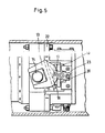
- the axial piston pump shown in the drawing has a flange 1, which ensures the connection with the corresponding supply and discharge lines for the hydraulic oil.
- the flange 1 is connected to a housing 2 by screws.
- a distributor 3 is fastened in the housing 2 and also carries the control plate 6.
- the drive shaft 5 is passed through the distributor 3 and the control plate 6.
- the drive shaft drives a cylinder drum 7 with a piston 8.
- the connection between the drive shaft 5 and the cylinder drum 7 takes place via a toothing sleeve 38 made of plastic or the like, damping Material with an internal and external tooth profile for the transmission of the torque.
- a helical spring 39 ensures a corresponding preload.
- a housing cap 4 which surrounds the other components of the axial piston pump, is fastened to the housing 2 with the aid of a tensioning band 35 and with the interposition of a sealing ring 37.
- the sliding shoes 11 are biased against the swash plate 10 by a pressure plate 9.
- the drive shaft 5 led out of the housing 2 on one side is supported in a slide bearing 52 with corresponding bearing shells and bearing rings.
- a sealing ring 53 which also rotates, ensures a corresponding seal. It is biased by several springs 56.
- a pin 55 ensures that the sealing ring 53 also rotates.
- a cover 54 forms the closure of the housing 2.
- the actual stator of the axial piston pump is formed by a central tube 41 which is mounted in the housing 2 via two plastic damping rings 57.
- This central tube 41 practically forms a support frame for absorbing all hydraulic forces, both in the axial and in the radial direction.
- the central tube serves to support the cylinder drum 7 forming the rotor and a pin ring 42 for guiding the swash plate 10 and for fastening the control base 22, which absorbs the axial forces of the swivel body bearing.
- the cylinder drum is supported by a freely rotating bearing ring 43 which has a number of radial lubrication bores 48 (FIG. 6).
- the cylinder drum 7 is received by a sleeve 45 which is supported axially and radially against the bearing ring 43.
- the sleeve forms a fit with the outer surface of the cylinder drum 7, which enables a relative axial movement.
- a relative rotational movement is prevented by a pin 46.
- Wave springs 47 which generate an axial preload, ensure that the bearing ring 43 runs smoothly.
- the preload simultaneously forms the static pressure of the cylinder drum 7 on the control plate 6.
- the freely rotating bearing ring 43 forms an inner lubricating gap Si with the sleeve 45 and an outer lubricating gap Sa with the central tube 41, so that two gaps functionally considered - are connected in series.
- the mean resulting lateral force of all pistons loaded on the pressure side of the pump runs in the direction of arrow Z (FIG. 6) and loads the bearing ring 43 in the center.
- the support of the bearing ring 43 on the other side is at an apertured supporting ring 49. Due to the described circumfluence of the position ring 43 is also formed in the gap to the support ring 49 during operation, a highly loaded hydrodynamic lubricating film 'from.
- the central tube 41, the pin ring 42, the support ring 49 and the control plate 6 are to be considered as stator parts.
- the cylinder drum 7 with the sleeve 45 rotate at the pump speed.
- a drag torque acts on the bearing ring 43 during operation, so that it rotates at about half the pump drive speed under normal operating conditions (approx. 100 ° C.).
- the swash plate 10 is pivotally mounted so that a variable piston stroke results when pivoted about a corresponding transverse axis.
- the swash plate 10 is screwed onto a swivel body 12.
- Lateral guide arms 13 of the swivel body 12 laterally each comprise a sliding block 15 which is rotatably mounted on the two pins 14 of the pin ring 42.
- the axis of rotation is identical to the transverse or pin axis M-M.
- the rear side of the swivel body 12 has a radius R in the areas L, so that when the swivel body 12 rotates about the pin axis M-M there is a linear movement of the running plate 16.
- a frictional engagement occurs between the swivel body 12 and the running plate 16, similar to how a loaded roller rolls on a flat surface, with the only difference that the roller — that is, swivel body 12 — is fixed in the axis MM is, and the documents speak running plate 16 - moves transversely to the axis MM.
- the swivel body 12 and the running plate 16 are coupled via guide grooves and rollers 17.
- the movement of the running plate 16 runs vertically.
- the running plate 16 is in turn supported on two linear roller bearings 10 which roll on fixed plates 19.
- a cage 20 is used which, like a frame, comprises the linear roller bearings and secures them in the respective position without play.
- the running plate 16 runs through twice the distance as the cage 20 or the linear roller bearing 18.
- the fixed plates 19 rest on damping plates 21 made of plastic, which in turn are arranged in corresponding chambers in the control floor 22.
- the control base 22 is screwed to the pin ring 42.
- the elastic deflection of this entire bearing point can be influenced in such a way that the bearing force introduced via a line contact (Hertzian pressure) between the swivel body 12 and the running plate 16 is evenly increased distributed all rolling elements of the linear roller bearings.
- the operating noises and the vibrations of the pump mechanism are isolated from the control base 22 by the damping plates 21 made of plastic.
- the position of the running plate 16 and the cage 20 with the two linear roller bearings 10, which is dependent on the respective swivel angle of the swivel body 12, is geometrically clearly determined by two rotatable brackets 23 screwed on the outside of the cage 20.
- the brackets are mounted in the coupling points on plastic bushings.
- the pump regulator 24 with the adjusting piston 25 is accommodated in the control base 22.
- the adjusting piston 25 is designed as a differential piston.
- a yoke 26 is screwed onto the rod end of the adjusting piston and comprises a bolt 27 in the form of a fork.
- the bolt is rotatably mounted in a bridge 25.
- the bridge 28 is screwed to the swivel body 12.
Landscapes
- Engineering & Computer Science (AREA)
- Mechanical Engineering (AREA)
- General Engineering & Computer Science (AREA)
- Reciprocating Pumps (AREA)
- Hydraulic Motors (AREA)
Applications Claiming Priority (2)
| Application Number | Priority Date | Filing Date | Title |
|---|---|---|---|
| DE3212402 | 1982-04-02 | ||
| DE3212402A DE3212402A1 (de) | 1982-04-02 | 1982-04-02 | Hydraulische axialkolbenmaschine |
Publications (3)
| Publication Number | Publication Date |
|---|---|
| EP0090206A2 EP0090206A2 (de) | 1983-10-05 |
| EP0090206A3 EP0090206A3 (en) | 1984-04-04 |
| EP0090206B1 true EP0090206B1 (de) | 1986-11-26 |
Family
ID=6160135
Family Applications (1)
| Application Number | Title | Priority Date | Filing Date |
|---|---|---|---|
| EP83102218A Expired EP0090206B1 (de) | 1982-04-02 | 1983-03-07 | Hydraulische Axialkolbenmaschine |
Country Status (3)
| Country | Link |
|---|---|
| EP (1) | EP0090206B1 (ja) |
| JP (1) | JPS58185982A (ja) |
| DE (2) | DE3212402A1 (ja) |
Families Citing this family (2)
| Publication number | Priority date | Publication date | Assignee | Title |
|---|---|---|---|---|
| DE4301119C2 (de) * | 1993-01-18 | 1995-03-30 | Danfoss As | Schrägscheibenanordnung in einer hydraulischen Axialkolbenmaschine |
| DE19800631A1 (de) * | 1998-01-09 | 1999-07-15 | Brueninghaus Hydromatik Gmbh | Axialkolbenmaschine mit Stützteil |
Family Cites Families (4)
| Publication number | Priority date | Publication date | Assignee | Title |
|---|---|---|---|---|
| DE1266132B (de) * | 1959-10-20 | 1968-04-11 | Materiels Hispano Suiza Sa Soc | "Anordnung des Kardangelenks fuer den angetriebenen Schiefschei-benlaufring einer Axialkolben-maschine" |
| JPS5532910B2 (ja) * | 1974-01-18 | 1980-08-27 | ||
| IT1087011B (it) * | 1976-10-19 | 1985-05-31 | Linde Ag | Macchina a stantuffi assiali del tipo di costruzione a flangia di trasmissione |
| JPS5948218B2 (ja) * | 1977-06-24 | 1984-11-24 | 住友化学工業株式会社 | 合成樹脂ペレットの気体輸送に於けるフロス発生低減方法 |
-
1982
- 1982-04-02 DE DE3212402A patent/DE3212402A1/de not_active Withdrawn
-
1983
- 1983-03-07 EP EP83102218A patent/EP0090206B1/de not_active Expired
- 1983-03-07 DE DE8383102218T patent/DE3367961D1/de not_active Expired
- 1983-03-29 JP JP58051761A patent/JPS58185982A/ja active Granted
Also Published As
| Publication number | Publication date |
|---|---|
| DE3212402A1 (de) | 1983-10-13 |
| EP0090206A2 (de) | 1983-10-05 |
| DE3367961D1 (en) | 1987-01-15 |
| EP0090206A3 (en) | 1984-04-04 |
| JPS58185982A (ja) | 1983-10-29 |
| JPH0341678B2 (ja) | 1991-06-24 |
Similar Documents
| Publication | Publication Date | Title |
|---|---|---|
| EP1886035B1 (de) | Schrägscheiben-schwenklager | |
| DE3239175C1 (de) | Lagerung des triebflansches einer axialkolbenmaschine in schraegachsen-bauart. | |
| EP0102915A2 (de) | Hydraulischer Radialkolbenmotor | |
| WO2003069174A1 (de) | Drehgleitlager | |
| WO2007140868A1 (de) | Axialkolbenmaschine mit hydrostatischer auflage des niederhalters | |
| EP0090953B1 (de) | Hydraulische Axialkolbenmaschine | |
| EP0728945B1 (de) | Axiakolbenmaschine | |
| DE10220610B4 (de) | Kolbenmaschine oder Drehgleitlagerung | |
| EP0090206B1 (de) | Hydraulische Axialkolbenmaschine | |
| EP1474616B1 (de) | Drehgleitlager | |
| DE3233579A1 (de) | Axialkolbenmaschine | |
| CH627527A5 (en) | Compressor unit, consisting of a drive motor and a compressor having eccentrically guided, freely mobile pistons | |
| DE3733083C2 (ja) | ||
| EP0090952B1 (de) | Hydraulische Axialkolbenmaschine | |
| EP0189786A2 (de) | Axial-Kolbenmaschine | |
| DE3606034C2 (ja) | ||
| DE10037481C1 (de) | Hydrostatische Verstellpumpe mit einem montage-verbesserten kompakten Gehäuse | |
| DE102019217204A1 (de) | Axialkolbenmaschine mit in der Verteilplatte gelagerten Antriebswelle | |
| DE19620654A1 (de) | Verstellbare Axialkolbenmaschine in Schrägscheibenbauweise | |
| DE69019152T2 (de) | Lagerschmierung in axialkolbenfluideinrichtungen. | |
| DE102018205884A1 (de) | Axialkolbenmaschine mit Druckentlastung in den Durchtriebsraum | |
| DE4022858A1 (de) | Axialkolbenmaschine | |
| DE4312053A1 (de) | Getriebe mit einer Verdrängerpumpe | |
| DE2932583C2 (de) | Hydraulische Axialkolbenmaschine in Schrägachsenbauweise | |
| DE69822067T2 (de) | Schmierfluidkanäle in der rotierenden Antriebsplatte eines Taumelscheibenkompressors |
Legal Events
| Date | Code | Title | Description |
|---|---|---|---|
| PUAI | Public reference made under article 153(3) epc to a published international application that has entered the european phase |
Free format text: ORIGINAL CODE: 0009012 |
|
| AK | Designated contracting states |
Designated state(s): DE FR GB IT |
|
| PUAL | Search report despatched |
Free format text: ORIGINAL CODE: 0009013 |
|
| AK | Designated contracting states |
Designated state(s): DE FR GB IT |
|
| RHK1 | Main classification (correction) |
Ipc: F04B 1/20 |
|
| 17P | Request for examination filed |
Effective date: 19840814 |
|
| RAP1 | Party data changed (applicant data changed or rights of an application transferred) |
Owner name: ABEX CORPORATION |
|
| GRAA | (expected) grant |
Free format text: ORIGINAL CODE: 0009210 |
|
| AK | Designated contracting states |
Kind code of ref document: B1 Designated state(s): DE FR GB IT |
|
| PG25 | Lapsed in a contracting state [announced via postgrant information from national office to epo] |
Ref country code: IT Free format text: LAPSE BECAUSE OF FAILURE TO SUBMIT A TRANSLATION OF THE DESCRIPTION OR TO PAY THE FEE WITHIN THE PRESCRIBED TIME-LIMIT;WARNING: LAPSES OF ITALIAN PATENTS WITH EFFECTIVE DATE BEFORE 2007 MAY HAVE OCCURRED AT ANY TIME BEFORE 2007. THE CORRECT EFFECTIVE DATE MAY BE DIFFERENT FROM THE ONE RECORDED. Effective date: 19861126 |
|
| REF | Corresponds to: |
Ref document number: 3367961 Country of ref document: DE Date of ref document: 19870115 |
|
| PLBE | No opposition filed within time limit |
Free format text: ORIGINAL CODE: 0009261 |
|
| STAA | Information on the status of an ep patent application or granted ep patent |
Free format text: STATUS: NO OPPOSITION FILED WITHIN TIME LIMIT |
|
| 26N | No opposition filed | ||
| PGFP | Annual fee paid to national office [announced via postgrant information from national office to epo] |
Ref country code: FR Payment date: 19900202 Year of fee payment: 8 |
|
| ITTA | It: last paid annual fee | ||
| PG25 | Lapsed in a contracting state [announced via postgrant information from national office to epo] |
Ref country code: FR Effective date: 19911129 |
|
| REG | Reference to a national code |
Ref country code: FR Ref legal event code: ST |
|
| PGFP | Annual fee paid to national office [announced via postgrant information from national office to epo] |
Ref country code: GB Payment date: 19920410 Year of fee payment: 10 |
|
| PGFP | Annual fee paid to national office [announced via postgrant information from national office to epo] |
Ref country code: DE Payment date: 19920415 Year of fee payment: 10 |
|
| PG25 | Lapsed in a contracting state [announced via postgrant information from national office to epo] |
Ref country code: GB Effective date: 19930307 |
|
| GBPC | Gb: european patent ceased through non-payment of renewal fee |
Effective date: 19930307 |
|
| PG25 | Lapsed in a contracting state [announced via postgrant information from national office to epo] |
Ref country code: DE Effective date: 19931201 |