EP0090206B1 - Hydraulic axial-piston machine - Google Patents
Hydraulic axial-piston machine Download PDFInfo
- Publication number
- EP0090206B1 EP0090206B1 EP83102218A EP83102218A EP0090206B1 EP 0090206 B1 EP0090206 B1 EP 0090206B1 EP 83102218 A EP83102218 A EP 83102218A EP 83102218 A EP83102218 A EP 83102218A EP 0090206 B1 EP0090206 B1 EP 0090206B1
- Authority
- EP
- European Patent Office
- Prior art keywords
- piston machine
- axial piston
- machine according
- linear roller
- ring
- Prior art date
- Legal status (The legal status is an assumption and is not a legal conclusion. Google has not performed a legal analysis and makes no representation as to the accuracy of the status listed.)
- Expired
Links
Images


Classifications
-
- F—MECHANICAL ENGINEERING; LIGHTING; HEATING; WEAPONS; BLASTING
- F04—POSITIVE - DISPLACEMENT MACHINES FOR LIQUIDS; PUMPS FOR LIQUIDS OR ELASTIC FLUIDS
- F04B—POSITIVE-DISPLACEMENT MACHINES FOR LIQUIDS; PUMPS
- F04B1/00—Multi-cylinder machines or pumps characterised by number or arrangement of cylinders
- F04B1/12—Multi-cylinder machines or pumps characterised by number or arrangement of cylinders having cylinder axes coaxial with, or parallel or inclined to, main shaft axis
- F04B1/20—Multi-cylinder machines or pumps characterised by number or arrangement of cylinders having cylinder axes coaxial with, or parallel or inclined to, main shaft axis having rotary cylinder block
- F04B1/2014—Details or component parts
- F04B1/2078—Swash plates
- F04B1/2085—Bearings for swash plates or driving axles
-
- F—MECHANICAL ENGINEERING; LIGHTING; HEATING; WEAPONS; BLASTING
- F05—INDEXING SCHEMES RELATING TO ENGINES OR PUMPS IN VARIOUS SUBCLASSES OF CLASSES F01-F04
- F05C—INDEXING SCHEME RELATING TO MATERIALS, MATERIAL PROPERTIES OR MATERIAL CHARACTERISTICS FOR MACHINES, ENGINES OR PUMPS OTHER THAN NON-POSITIVE-DISPLACEMENT MACHINES OR ENGINES
- F05C2253/00—Other material characteristics; Treatment of material
- F05C2253/12—Coating
Definitions
- the invention relates to a hydraulic axial piston machine according to the preamble of claim 1.
- Rolling bearings for such tasks are expensive, place high demands on the geometry of the adjacent parts and cannot be used in accordance with the theoretical static load rating due to the internal clearance conditions and the resulting point load for the outer ring.
- the vibrations and forces of the pump mechanism prematurely lead to material fatigue in the rolling contact zone or the bearings must be oversized in accordance with the required service life.
- Hydrostatic bearings are lossy and require an increased build volume.
- the invention is based on the object of a hydraulic axial piston machine, i.e. to create a pump or a motor, which is of compact construction and is correspondingly rigid, so that a low-vibration construction is created, and in particular is low-noise.
- the axial piston machine is advantageously designed as specified in claims 3 and 4, then the span between the two linear roller bearings is small. If one makes the following theoretical considerations, essential advantages become clear.
- the support of the resulting axial force on the pressure side of the machine - seen here as a mechanical model - represents a beam on two supports with line load. Since bending vibrations are primarily responsible for noise emissions before all other forms of vibration, the linear roller bearings are arranged as close as possible to the line of action of the resulting axial force . This line of action oscillates slightly (in a practical embodiment around an average of 0.63 of the pitch circle radius of the piston path). Thus, with minimal elastic deflection of the bearing points, the resulting axial force is applied to the corresponding support, i.e. transferred to the damping plates. Due to their good damping behavior, these effectively couple the excitation vibrations of the swivel body from the control floor.
- the axial piston pump shown in the drawing has a flange 1, which ensures the connection with the corresponding supply and discharge lines for the hydraulic oil.
- the flange 1 is connected to a housing 2 by screws.
- a distributor 3 is fastened in the housing 2 and also carries the control plate 6.
- the drive shaft 5 is passed through the distributor 3 and the control plate 6.
- the drive shaft drives a cylinder drum 7 with a piston 8.
- the connection between the drive shaft 5 and the cylinder drum 7 takes place via a toothing sleeve 38 made of plastic or the like, damping Material with an internal and external tooth profile for the transmission of the torque.
- a helical spring 39 ensures a corresponding preload.
- a housing cap 4 which surrounds the other components of the axial piston pump, is fastened to the housing 2 with the aid of a tensioning band 35 and with the interposition of a sealing ring 37.
- the sliding shoes 11 are biased against the swash plate 10 by a pressure plate 9.
- the drive shaft 5 led out of the housing 2 on one side is supported in a slide bearing 52 with corresponding bearing shells and bearing rings.
- a sealing ring 53 which also rotates, ensures a corresponding seal. It is biased by several springs 56.
- a pin 55 ensures that the sealing ring 53 also rotates.
- a cover 54 forms the closure of the housing 2.
- the actual stator of the axial piston pump is formed by a central tube 41 which is mounted in the housing 2 via two plastic damping rings 57.
- This central tube 41 practically forms a support frame for absorbing all hydraulic forces, both in the axial and in the radial direction.
- the central tube serves to support the cylinder drum 7 forming the rotor and a pin ring 42 for guiding the swash plate 10 and for fastening the control base 22, which absorbs the axial forces of the swivel body bearing.
- the cylinder drum is supported by a freely rotating bearing ring 43 which has a number of radial lubrication bores 48 (FIG. 6).
- the cylinder drum 7 is received by a sleeve 45 which is supported axially and radially against the bearing ring 43.
- the sleeve forms a fit with the outer surface of the cylinder drum 7, which enables a relative axial movement.
- a relative rotational movement is prevented by a pin 46.
- Wave springs 47 which generate an axial preload, ensure that the bearing ring 43 runs smoothly.
- the preload simultaneously forms the static pressure of the cylinder drum 7 on the control plate 6.
- the freely rotating bearing ring 43 forms an inner lubricating gap Si with the sleeve 45 and an outer lubricating gap Sa with the central tube 41, so that two gaps functionally considered - are connected in series.
- the mean resulting lateral force of all pistons loaded on the pressure side of the pump runs in the direction of arrow Z (FIG. 6) and loads the bearing ring 43 in the center.
- the support of the bearing ring 43 on the other side is at an apertured supporting ring 49. Due to the described circumfluence of the position ring 43 is also formed in the gap to the support ring 49 during operation, a highly loaded hydrodynamic lubricating film 'from.
- the central tube 41, the pin ring 42, the support ring 49 and the control plate 6 are to be considered as stator parts.
- the cylinder drum 7 with the sleeve 45 rotate at the pump speed.
- a drag torque acts on the bearing ring 43 during operation, so that it rotates at about half the pump drive speed under normal operating conditions (approx. 100 ° C.).
- the swash plate 10 is pivotally mounted so that a variable piston stroke results when pivoted about a corresponding transverse axis.
- the swash plate 10 is screwed onto a swivel body 12.
- Lateral guide arms 13 of the swivel body 12 laterally each comprise a sliding block 15 which is rotatably mounted on the two pins 14 of the pin ring 42.
- the axis of rotation is identical to the transverse or pin axis M-M.
- the rear side of the swivel body 12 has a radius R in the areas L, so that when the swivel body 12 rotates about the pin axis M-M there is a linear movement of the running plate 16.
- a frictional engagement occurs between the swivel body 12 and the running plate 16, similar to how a loaded roller rolls on a flat surface, with the only difference that the roller — that is, swivel body 12 — is fixed in the axis MM is, and the documents speak running plate 16 - moves transversely to the axis MM.
- the swivel body 12 and the running plate 16 are coupled via guide grooves and rollers 17.
- the movement of the running plate 16 runs vertically.
- the running plate 16 is in turn supported on two linear roller bearings 10 which roll on fixed plates 19.
- a cage 20 is used which, like a frame, comprises the linear roller bearings and secures them in the respective position without play.
- the running plate 16 runs through twice the distance as the cage 20 or the linear roller bearing 18.
- the fixed plates 19 rest on damping plates 21 made of plastic, which in turn are arranged in corresponding chambers in the control floor 22.
- the control base 22 is screwed to the pin ring 42.
- the elastic deflection of this entire bearing point can be influenced in such a way that the bearing force introduced via a line contact (Hertzian pressure) between the swivel body 12 and the running plate 16 is evenly increased distributed all rolling elements of the linear roller bearings.
- the operating noises and the vibrations of the pump mechanism are isolated from the control base 22 by the damping plates 21 made of plastic.
- the position of the running plate 16 and the cage 20 with the two linear roller bearings 10, which is dependent on the respective swivel angle of the swivel body 12, is geometrically clearly determined by two rotatable brackets 23 screwed on the outside of the cage 20.
- the brackets are mounted in the coupling points on plastic bushings.
- the pump regulator 24 with the adjusting piston 25 is accommodated in the control base 22.
- the adjusting piston 25 is designed as a differential piston.
- a yoke 26 is screwed onto the rod end of the adjusting piston and comprises a bolt 27 in the form of a fork.
- the bolt is rotatably mounted in a bridge 25.
- the bridge 28 is screwed to the swivel body 12.
Landscapes
- Engineering & Computer Science (AREA)
- Mechanical Engineering (AREA)
- General Engineering & Computer Science (AREA)
- Reciprocating Pumps (AREA)
- Hydraulic Motors (AREA)
Description
Die Erfindung betrifft eine hydraulische Axialkolbenmaschine nach dem Oberbegriff des Anspruches 1.The invention relates to a hydraulic axial piston machine according to the preamble of claim 1.
Es sind die unterschiedlichsten hydraulischen Axialkolbenmaschinen der vorstehend genannten Art bekannt. Bei einer bekannten Axialkolbenmaschine nehmen die Zapfen die gesamten hydraulischen Kräfte, d.h. die Axial-und die Radial-Kräfte, auf. Der Steuerkolben zur Durchführung der Schwenkbewegung der Schrägscheibe ist in dem Stator angeordnet, der die Zylindertrommel umgibt. (DE-B-1915 735).A wide variety of hydraulic axial piston machines of the type mentioned above are known. In a known axial piston machine, the pins take up the entire hydraulic forces, i.e. the axial and radial forces. The control piston for carrying out the swiveling movement of the swash plate is arranged in the stator which surrounds the cylinder drum. (DE-B-1915 735).
Es sind anders aufgebaute Axialkolbenpumpen der Schrägscheibenbauart bekannt, bei denen die Schrägscheibe ähnlich einer Wippe in den Innenringen von Wälzlagern gelagert sind. Es sind auch Konstruktionen bekannt, bei denen die Drehzapfen bzw. die Lagerflächen als hydrostatische Lager mit kreisrunden Bahnen ausgebildet sind.Different design axial piston pumps of the swashplate design are known, in which the swashplate is mounted in the inner rings of roller bearings like a rocker. Constructions are also known in which the pivots or the bearing surfaces are designed as hydrostatic bearings with circular tracks.
Wälzlagerungen für derartige Aufgaben sind teuer, stellen hohe Anforderungen an die Geometrie der benachbarten Teile und können infolge der Lagerluft-Verhältnisse und dadurch verursachten Punktlast für den Außenring nicht entsprechend der theoretischen statischen Tragzahl ausgenutzt werden. Die Schwingungen und Kräfte des Pumpen-Mechanismus führen vorzeitig zur Materialermüdung in der Wälzkontakt-Zone oder die Lager müssen entsprechend der geforderten Lebensdauer überdimensioniert werden. Diese Maßnahmen wirken sich zusätzlich ungünstig auf die Kosten und das Bauvolumen aus.Rolling bearings for such tasks are expensive, place high demands on the geometry of the adjacent parts and cannot be used in accordance with the theoretical static load rating due to the internal clearance conditions and the resulting point load for the outer ring. The vibrations and forces of the pump mechanism prematurely lead to material fatigue in the rolling contact zone or the bearings must be oversized in accordance with the required service life. These measures also have an unfavorable impact on costs and construction volume.
Hydrostatische Lager sind verlustbehaftet, und erfodern ein vergrößertes Bauvolumen.Hydrostatic bearings are lossy and require an increased build volume.
Der Erfindung liegt nun die Aufgabe zugrunde, eine hydraulische Axialkolbenmaschine, d.h. eine Pumpe oder einen Motor zu schaffen, die kompakt aufgebaut und entsprechend steif ist, so daß eine schwingungsarme Konstruktion entsteht, und insbesondere geräuscharm ist.The invention is based on the object of a hydraulic axial piston machine, i.e. to create a pump or a motor, which is of compact construction and is correspondingly rigid, so that a low-vibration construction is created, and in particular is low-noise.
Diese Aufgabe wird grundsätzlich durch das Kennzeichen des Anspruches 1 gelöst.This object is basically achieved by the characterizing part of claim 1.
Sämtliche während des Betriebes auftretenden Axialkräfte werden durch die gekrümmte Fläche auf das Linearrollenlager übertragen, bei dem es sich um ein einfaches, in Großserie hergestelltes Maschinenelement handelt. Die Ausgestaltung und Dimensionierung wird hierbei so vorgenommen, daß die auf die Laufplatte übertragene Kraft gleichmäßig auf alle Wälzkörper verteilt wird. Die erfindungsgemäße Lagerung verhindert Biegeschwingungen und damit die durch diese entstehenden Geräuse. Praktisch erfolgt die Lagerung dort, wo die resultierende Kraft der Axialkolben auftritt. Weitere Vorteile und Einzelheiten sind Gegenstand der Ansprüche 1 bis 7.All of the axial forces that occur during operation are transmitted through the curved surface to the linear roller bearing, which is a simple, mass-produced machine element. The design and dimensioning is carried out so that the force transmitted to the running plate is evenly distributed over all rolling elements. The storage according to the invention prevents bending vibrations and thus the noise generated by them. In practice, the bearings are placed where the resulting force of the axial pistons occurs. Further advantages and details are the subject of claims 1 to 7.
Wenn die Axialkolbenmaschine in vorteilhafter Weise so ausgebildet ist, wie in den Ansprüchen 3 und 4 angegeben, dann ist die Stützweite zwischen den beiden Linearrollenlagern gering. Wenn man folgende theoretischen Überlegungen anstellt, werden wesentliche Vorteile deutlich. Die Abstützung der resultierenden Axialkraft auf der Druckseite der Maschine stellt - hier als mechanisches Modell betrachtet - einen Träger auf zwei Stützen mit Streckenlast dar. Da Biegeschwingungen vorrangig vor allen anderen Schwingungsformen für Geräuschemissionen verantwortlich sind, werden die Linearrollenlager möglichst nahe zur Wirkungslinie der resultierenden Axialkraft angeordnet. Diese Wirkungslinie oszilliert geringfügig (bei einer praktischen Ausführungsform um einen Mittelwert von 0,63 des Teilkreisradius der Kolbenbahn). Somit wird mit geringsten elastischen Einfederungen der Lagerstellen die resultierende Axialkraft auf die entsprechende Abstützung, d.h. auf die Dämpfungsplatten übertragen. Diese koppeln aufgrund ihres guten Dämpfungsverhaltens die Erregerschwingungen des Schwenkkörpers wirkungsvoll vom Steuerboden ab.If the axial piston machine is advantageously designed as specified in
Die Anordnung des Verstellkolbens in dem Steuerboden, der mit dem Zapfenring verbunden ist (Anspruch 6), sorgt für eine kompakte Ausbildung.The arrangement of the adjusting piston in the control base, which is connected to the pin ring (claim 6), ensures a compact design.
Weitere Vorteile und Einzelheiten der Erfindung werden im folgenden unter Hinweis auf die Zeichnung näher erläutert.Further advantages and details of the invention are explained in more detail below with reference to the drawing.
Es zeigt:
- Fig. 1 einen Längsschnitt durch eine Ausführungsform einer Axialkolbenmaschime nach der Erfindung, nämlich durch eine Axialkolbenpumpe;
- Fig. 2 einen Längsschnitt durch die Axialkolbenpumpe der Fig. 1, jedoch um 90° gedreht; Fig. 3 einen Querschnitt gemäß der Linie A-A der Fig. 1;
- Fig. 4 einen Schnitt gemäß der Linie B-B der Fig. 2;
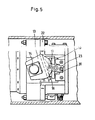
- Fig. 5 eine Ansicht in Richtung des Pfeiles X der Fig. 2;
- Fig. 6 eine Einzelheit aus dem Schnitt der Fig.
- Fig. 7 eine Seitenansicht der Darstellung der Fig. 6; und
- Fig. 8 eine Ansicht, die derjenigen der Fig.6 entspricht, jedoch die wesentlichen Bauteile im nichtgeschnittenen Zustand zeigt.
- 1 shows a longitudinal section through an embodiment of an axial piston machine according to the invention, namely through an axial piston pump.
- FIG. 2 shows a longitudinal section through the axial piston pump of FIG. 1, but rotated through 90 °; 3 shows a cross section along the line AA of FIG. 1.
- 4 shows a section along the line BB of FIG. 2.
- Fig. 5 is a view in the direction of arrow X of Fig. 2;
- 6 shows a detail from the section of FIG.
- Fig. 7 is a side view of the illustration of Fig. 6; and
- Fig. 8 is a view that corresponds to that of Figure 6, but shows the essential components in the uncut state.
Die in der Zeichnung dargestellte Axialkolbenpumpe besitzt einen Flansch 1, der für die Verbindung mit den entsprechenden Zu- und Ableitungen für das Hydrauliköl sorgt. Der Flansch 1 ist durch Schrauben mit einem Gehäuse 2 verbunden.The axial piston pump shown in the drawing has a flange 1, which ensures the connection with the corresponding supply and discharge lines for the hydraulic oil. The flange 1 is connected to a housing 2 by screws.
In dem Gehäuse 2 ist ein Verteiler 3 befestigt der auch die Steuerplatte 6 trägt Durch den Verteiler 3 und die Steuerplatte 6 ist die Antriebswelle 5 hindurchgeführt.A
Die Antriebswelle treibt eine Zylindertrommel 7 mit Kolben 8. Die Verbindung zwischen der Antriebswelle 5 und der Zylindertrommel 7 erfolgt über eine Verzahnungshülse 38 aus Kunststoff oder ähnlichem dämpfenden Werkstoff mit einem Innen- und Außenzahnprofil zur Übertrages des Drehmomentes. Für eine entsprechende Vorspannung sorgt eine Schraubenfeder 39.The drive shaft drives a
An dem Gehäuse 2 ist mit Hilfe eines Spannbandes 35 und unter Zwischenschaltung eines Dichtungsringes 37 eine Gehäusekappe 4 befestigt, welche die übrigen Bauteile der Axialkolbenpumpe umgibt. Dieses sind insbesondere die Schrägscheibe 10, an der sich die Gleitschuhe 11 abstützen. Die Gleitschuhe 11 sind durch eine Andrückplatte 9 gegen die Schrägscheibe 10 vorgespannt.A housing cap 4, which surrounds the other components of the axial piston pump, is fastened to the housing 2 with the aid of a
Die einseitig aus dem Gehäuse 2 herausgeführte Antriebswelle 5 ist in einem Gleitlager 52 mit entsprechenden Lagerschalen und Lagerringen gelagert. Ein Dichtungsring 53, der mitrotiert, sorgt für eine entsprechende Abdichtung. Er wird durch mehrere Federn 56 vorgespannt. Ein Stift 55 stellt sicher, daß sich der Dichtungsring 53 mitdreht. Ein Deckel 54 bilden den Verschluß des Gehäuses 2.The
Der eigentliche Stator der Axialkolbenpumpe wird durch ein Zentralrohr 41 gebildet, das über zwei Dämpfungsringe 57 aus Kunststoff in dem Gehäuse 2 gelagert ist. Dieses Zentralrohr 41 bildet praktisch einen Stützrahmen zur Aufnahme sämtlicher hydraulischer Kräfte,und zwar sowohl in axialer als auch in radialer Richtung. Das Zentralrohr dient der Abstützung der den Rotor bildenden Zylindertrommel 7, und eines Zapfenringes 42 zur Führung der Schrägscheibe 10 sowie zur Befestigung des Steuerbodens 22, welcher die axialen Kräfte der Schwenkkörper-Lagerung aufnimmt.The actual stator of the axial piston pump is formed by a
Die Abstützung der Zylindertrommel erfolgt über einen frei umlaufenden Lagerring 43, der eine Anzahl radialer Schmierbohrungen 48 (Fig. 6) aufweist. Die Zylindertrommel 7 wird von einer Hülse 45 aufgenommen, die sich axial und radial gegen den Lagerring 43 abstützt. Die Hülse bildet mit der Außenfläche der Zylindertrommel 7 eine Passung, die eine relative axiale Bewegung ermöglicht. Eine relative Drehbewegung wird durch einen Stift 46 verhindert.The cylinder drum is supported by a freely rotating bearing
Für den ruhigen Lauf des Lagerringes 43 sorgen Wellenfedern 47, die eine axiale Vorspannung erzeugen. Die Vorspannung bildet gleichzeitig die statische Anpressung der Zylindertrommel 7 an die Steuerplatte 6.
Der frei umlaufende Lagerring 43 bildet mit der Hülse 45 einen inneren Schmierspalt Si und mit dem Zentralrohr 41 einen äußeren Schmierspalt Sa, so daß zwei Spaltefunktionstechnich betrachtet - in Reihe geschaltet sind. Die mittlere resultierende Seitenkraft aller auf der Druckseite der Pumpe belasteten Kolben verläuft in Richtung des Pfeiles Z (Fig. 6) und belastet den Lagerring 43 mittig.The freely rotating
Der Aufbau von zwei hochbelastbaren hydrodynamischen Öldruckfilmen in den Spalten Si und Sa wird unterstützt durch zwangsweise vor der Druckzone über eine Mengendrossel zugeführtes Drucköl von der Hochdruckseite der Pumpe. Die Zuführung geschieht über eine Versorgungsleitung 51. Durch die radialen Schmierbohrungen 48 in dem Lagerring 43 wird der Schmierspalt Si versorgt. Zum Aufbau eines tragfähigen hydrodynamischen Schmierfilms an den Seitenflächen des Lagerringes43 sind entsprechend ausgebildete, drehrichtungsabhängig geformte Schmierkanäle 50 (Fig. 8) an dem Wulst 44 der Hülse 45 ausgebildet. Hierdurch wird der Lagerring 43 während des Betriebes mit Planschöl aus dem Pumpengehäuse umflutet.The build-up of two heavy-duty hydrodynamic oil pressure films in the Si and Sa columns is supported by pressure oil from the high-pressure side of the pump, which is forced in front of the pressure zone via a flow restrictor. The supply takes place via a
Die Abstützung des Lagerringes 43 auf der anderen Seite erfolgt gegen einen mit Durchbrüchen versehenen Stützring 49. Bedingt durch die beschriebene Umflutung des Lageringes 43 bildet sich auch im Spalt zu dem Stützring 49 im Betrieb ein hochbelasteter hydrodynamischer Schmierfilm'aus.The support of the
Das Zentralrohr 41, der Zapfenring 42, der Stützring 49 und die Steuerplatte 6 sind als Statorteile zu betrachten. Die Zylindertrommel 7 mit der Hülse 45 drehen sich mit Pumpendrehzahl. Infolge der viskosen Flüssikgeitsreibung in den Schmierspalten Si und Sa wirkt im Betrieb auf den Lagerring 43 ein Schleppmoment, so daß sich dieser bei normalen Betriebsbedinungen (ca. 100° C) etwa mit der halben Pumpenantriebsdrehzahl dreht.The
Da es sich bei der veranschaulichten Axialkolbenpumpe um eine solche mit veränderlichem Hubvolumen handelt, ist die Schrägscheibe 10 schwenkbar gelagert, so daß sich bei Schwenkung um eine entsprechende Querachse ein veränderlicher Kolbenhub ergibt. Bei der dargestellten Ausführungsform ist die Schrägscheibe 10 auf einem Schwenkkörper 12 verschraubt. Seitliche Führungsarme 13 des Schwenkkörpers 12 umfassen seitlich jeweils einen auf den beiden Zapfen 14 des Zapfenringes 42 drehbar gelagerten Gleitstein 15. Die Drehachse ist identisch mit Queroder Zapfenachse M-M. Die Rückseite des Schwenkkörpers 12 besitzt in den Bereichen L einen Radius R so daß sich bei der Drehung des Schwenkkörpers 12 um die Zapfenachse M-M eine Linearbewegung der Laufplatte 16 ergibt. Infolge der großen axialen Kolbenkräfte in der Druckzone entsteht zwischen dem Schwenkkörper 12 und der Laufplatte 16 ein Reibschluß, ähnlich wie eine belastete Walze auf einer ebenen Unterlage abrollt, nur mit dem Unterschied, daß hier die Walze-sprich Schwenkkörper 12 - in der Achse M-M fixiert ist, und die Unterlagen sprich Laufplatte 16 - sich quer zur Achse M-M bewegt. Der Schwenkkörper 12 und die Laufplatte 16 sind über Führungsnuten und -rollen 17 gekoppelt.Since the illustrated axial piston pump is one with a variable stroke volume, the
Unter Zugrundelegung der Darstellung der Fig. 4 verläuft die Bewegung der Laufplatte 16 in der Vertikalen. Die Laufplatte 16 stützt sich wiederum auf zwei Linearrollenlager 10 ab, die auf Fixplatten 19 abrollen. Zur Lagesicherung der Linearrollenlager 10 dient ein Käfig 20, der wie ein Rahmen die Linerarrollenlager umfaßt und spielfrei in der jeweiligen Stellung sichert.Based on the illustration in FIG. 4, the movement of the running
Bei Einleitung einer Schwenkbewegung durchläuft die Laufplatte 16 die doppelte Wegstrecke wie der Käfig 20 bzw. die Linearrollenlager 18.When a swiveling movement is initiated, the running
Die Fixplatten 19 liegen auf Dämpfungsplatten 21 aus Kunststoff auf, die wiederum in entsprechenden Kammern in dem Steuerboden 22 angeordnet sind. Der Steuerboden 22 ist mit dem Zapfenring 42 verschraubt.The fixed
Durch entsprechende Berechnung der Steifigkeit der Laufplatte 16, der Fixplatten 19 und der Dämpfungsplatten 21, kann die elastische Durchbiegung dieser gesamten Lagerstelle so beeinflußt werden, daß sich die über eine Linienberührung (Hertz'sche Pressung) zwischen Schwenkkörper 12 und Laufptatte 16 eingeleitete Lagerkraft gleichmäßig auf alle Wälzkörper der Linearrollenlager verteilt. Durch die Dämpfungsplatten 21 aus Kunststoff werden die Betriebsgeräuche und die Schwingungen der Pumpenmechanik vom Steuerboden 22 isoliert.By appropriately calculating the rigidity of the running
Die vom jeweiligen Schwenkwinkel des Schwenkkörpers 12 abhängige Stellung der Laufplatte 16 und des Käfigs 20 mit den beiden Linearrollenlagern 10 wird geometrisch eindeutig bestimmt durch zwei jeweils außen am Käfig 20 angeschraubte, drehbare Laschen 23. Die Laschen sind in den Kopplungspunkten auf Büchsen aus Kunststoff gelagert.The position of the running
Im Steuerboden 22 ist der Pumpenregler 24 mit dem Verstellkolben 25 untergebracht. Der Verstellkolben 25 ist als Differentialkolben ausgebildet. Am Stangenende des Verstellkolbens ist ein Joch 26 angeschraubt, das in Form einer Gabel einen Bolzen 27 umfaßt. Der Bolzen ist in einer Brücke 25 drehbar gelagert. Die Brücke 28 ist mit dem Schwenkkörper 12 verschraubt.The
Die druckabhängig vom Pumpenregler 24 geregelte Position des Verstellkolbens 25 wird somit formschlüssig auf den Schwenkkörper 12 übertragen, d.h. einer bestimmten Stellung des Verstellkolbens entspricht ein bestimmter Winkel der Schrägscheibe 10 und damit einem bestimmten Hubvolumen der Pumpe.The position of the
Die Abstützung des Schwenkkörpers 12 über die beschriebene Lagerung mittels Linearrollenlager auf dem Steuerboden 22, in dem auch die komplette Pumpenregler mit Verstellkolben untergebracht ist, ergibt infolge der Verschraubung mit dem Zapfenring 42 und dem Zentralrohr 41 eine äußerst kompakte, steife und damit schwingungsarme Konstruktion, die auch insbesondere hinsichtlich der Geräuschemission erhebliche Vorteile bildet. Wie beim Betrachten der Fig. 3 deutlich wird, sind in der Steuerplatte 6 Steuerschlitze 32 und 33 ausgebildet, die für eine Verbindung mit der Saugleitung 30 bzw. der Druckleitung 31 sorgen. Hülsen 34 aus Kunststoff stellen eine schalltechnische Abkoppelung des Verteilers 3 vom Gehäuse 2 dar und tragen deshalb zur Geräuschdämpfung bei. Von der Druckseite wird eine Leitung 36 mit Drucköl versorgt, die wiederum den Pumpenregler 24 als auch den Kanal 51 mit Drucköl versorgt.The support of the swivel body 12 via the described bearing by means of linear roller bearings on the

Claims (7)
Applications Claiming Priority (2)
| Application Number | Priority Date | Filing Date | Title |
|---|---|---|---|
| DE3212402 | 1982-04-02 | ||
| DE3212402A DE3212402A1 (en) | 1982-04-02 | 1982-04-02 | HYDRAULIC AXIAL PISTON MACHINE |
Publications (3)
| Publication Number | Publication Date |
|---|---|
| EP0090206A2 EP0090206A2 (en) | 1983-10-05 |
| EP0090206A3 EP0090206A3 (en) | 1984-04-04 |
| EP0090206B1 true EP0090206B1 (en) | 1986-11-26 |
Family
ID=6160135
Family Applications (1)
| Application Number | Title | Priority Date | Filing Date |
|---|---|---|---|
| EP83102218A Expired EP0090206B1 (en) | 1982-04-02 | 1983-03-07 | Hydraulic axial-piston machine |
Country Status (3)
| Country | Link |
|---|---|
| EP (1) | EP0090206B1 (en) |
| JP (1) | JPS58185982A (en) |
| DE (2) | DE3212402A1 (en) |
Families Citing this family (2)
| Publication number | Priority date | Publication date | Assignee | Title |
|---|---|---|---|---|
| DE4301119C2 (en) * | 1993-01-18 | 1995-03-30 | Danfoss As | Swashplate arrangement in a hydraulic axial piston machine |
| DE19800631A1 (en) * | 1998-01-09 | 1999-07-15 | Brueninghaus Hydromatik Gmbh | Axial piston machine with support part |
Family Cites Families (4)
| Publication number | Priority date | Publication date | Assignee | Title |
|---|---|---|---|---|
| DE1266132B (en) * | 1959-10-20 | 1968-04-11 | Materiels Hispano Suiza Sa Soc | "Arrangement of the universal joint for the driven swashplate raceway of an axial piston machine" |
| JPS5532910B2 (en) * | 1974-01-18 | 1980-08-27 | ||
| IT1087011B (en) * | 1976-10-19 | 1985-05-31 | Linde Ag | AXIAL PISTON MACHINE OF THE CONSTRUCTION TYPE WITH TRANSMISSION FLANGE |
| JPS5948218B2 (en) * | 1977-06-24 | 1984-11-24 | 住友化学工業株式会社 | Method for reducing froth generation during gas transportation of synthetic resin pellets |
-
1982
- 1982-04-02 DE DE3212402A patent/DE3212402A1/en not_active Withdrawn
-
1983
- 1983-03-07 DE DE8383102218T patent/DE3367961D1/en not_active Expired
- 1983-03-07 EP EP83102218A patent/EP0090206B1/en not_active Expired
- 1983-03-29 JP JP58051761A patent/JPS58185982A/en active Granted
Also Published As
| Publication number | Publication date |
|---|---|
| EP0090206A2 (en) | 1983-10-05 |
| EP0090206A3 (en) | 1984-04-04 |
| JPH0341678B2 (en) | 1991-06-24 |
| DE3367961D1 (en) | 1987-01-15 |
| JPS58185982A (en) | 1983-10-29 |
| DE3212402A1 (en) | 1983-10-13 |
Similar Documents
| Publication | Publication Date | Title |
|---|---|---|
| EP1886035B1 (en) | Swash plate pivot bearing | |
| DE3239175C1 (en) | BEARING OF THE DRIVE FLANGE OF AN AXIAL PISTON MACHINE IN SCHRAEGACHSEN DESIGN. | |
| EP0102915A2 (en) | Radial-piston hydraulic engine | |
| EP1474617A1 (en) | Swivel slide bearing | |
| WO2007140868A1 (en) | Axial piston machine having a hydrostatic support of the hold-down | |
| EP0090953B1 (en) | Hydraulic axial-piston machine | |
| EP1474616B1 (en) | Rotation-slide bearing | |
| DE2710734C3 (en) | ||
| EP0728945B1 (en) | Axial piston machine | |
| DE10220610B4 (en) | Piston machine or rotary plain bearing | |
| EP0090206B1 (en) | Hydraulic axial-piston machine | |
| DE3233579A1 (en) | AXIAL PISTON MACHINE | |
| EP0090952B1 (en) | Hydraulic axial-piston machine | |
| EP0189786A2 (en) | Axial-piston machine | |
| DE3033939C2 (en) | Conical pulley for continuously adjustable conical pulley belt drive | |
| DE3606034C2 (en) | ||
| DE3733083A1 (en) | ADJUSTABLE AXIAL PISTON MACHINE IN SWASHING DISC DESIGN | |
| DE10037481C1 (en) | Hydrostatic variable displacement pump has the largest dimension of the swash plate made larger than the distance between the bearing seats of the first and second bearings | |
| DE102019217204A1 (en) | Axial piston machine with drive shaft mounted in the distributor plate | |
| DE19620654A1 (en) | Adjustable stroke axial piston machine | |
| DE102018205884A1 (en) | Axial piston machine with pressure relief in the Durchtriebsraum | |
| DE4022858A1 (en) | Axial piston machine - with pistons running on cam track with two top and two bottom dead-centres | |
| DE4312053A1 (en) | Transmission with a positive displacement pump | |
| DE2932583C2 (en) | Hydraulic axial piston machine in bent axis design | |
| DE69822067T2 (en) | Lubricating fluid channels in the rotating drive plate of a swash plate compressor |
Legal Events
| Date | Code | Title | Description |
|---|---|---|---|
| PUAI | Public reference made under article 153(3) epc to a published international application that has entered the european phase |
Free format text: ORIGINAL CODE: 0009012 |
|
| AK | Designated contracting states |
Designated state(s): DE FR GB IT |
|
| PUAL | Search report despatched |
Free format text: ORIGINAL CODE: 0009013 |
|
| AK | Designated contracting states |
Designated state(s): DE FR GB IT |
|
| RHK1 | Main classification (correction) |
Ipc: F04B 1/20 |
|
| 17P | Request for examination filed |
Effective date: 19840814 |
|
| RAP1 | Party data changed (applicant data changed or rights of an application transferred) |
Owner name: ABEX CORPORATION |
|
| GRAA | (expected) grant |
Free format text: ORIGINAL CODE: 0009210 |
|
| AK | Designated contracting states |
Kind code of ref document: B1 Designated state(s): DE FR GB IT |
|
| PG25 | Lapsed in a contracting state [announced via postgrant information from national office to epo] |
Ref country code: IT Free format text: LAPSE BECAUSE OF FAILURE TO SUBMIT A TRANSLATION OF THE DESCRIPTION OR TO PAY THE FEE WITHIN THE PRESCRIBED TIME-LIMIT;WARNING: LAPSES OF ITALIAN PATENTS WITH EFFECTIVE DATE BEFORE 2007 MAY HAVE OCCURRED AT ANY TIME BEFORE 2007. THE CORRECT EFFECTIVE DATE MAY BE DIFFERENT FROM THE ONE RECORDED. Effective date: 19861126 |
|
| REF | Corresponds to: |
Ref document number: 3367961 Country of ref document: DE Date of ref document: 19870115 |
|
| PLBE | No opposition filed within time limit |
Free format text: ORIGINAL CODE: 0009261 |
|
| STAA | Information on the status of an ep patent application or granted ep patent |
Free format text: STATUS: NO OPPOSITION FILED WITHIN TIME LIMIT |
|
| 26N | No opposition filed | ||
| PGFP | Annual fee paid to national office [announced via postgrant information from national office to epo] |
Ref country code: FR Payment date: 19900202 Year of fee payment: 8 |
|
| ITTA | It: last paid annual fee | ||
| PG25 | Lapsed in a contracting state [announced via postgrant information from national office to epo] |
Ref country code: FR Effective date: 19911129 |
|
| REG | Reference to a national code |
Ref country code: FR Ref legal event code: ST |
|
| PGFP | Annual fee paid to national office [announced via postgrant information from national office to epo] |
Ref country code: GB Payment date: 19920410 Year of fee payment: 10 |
|
| PGFP | Annual fee paid to national office [announced via postgrant information from national office to epo] |
Ref country code: DE Payment date: 19920415 Year of fee payment: 10 |
|
| PG25 | Lapsed in a contracting state [announced via postgrant information from national office to epo] |
Ref country code: GB Effective date: 19930307 |
|
| GBPC | Gb: european patent ceased through non-payment of renewal fee |
Effective date: 19930307 |
|
| PG25 | Lapsed in a contracting state [announced via postgrant information from national office to epo] |
Ref country code: DE Effective date: 19931201 |