EP0089403B1 - Nachgiebiger Betonsegmentausbau - Google Patents
Nachgiebiger Betonsegmentausbau Download PDFInfo
- Publication number
- EP0089403B1 EP0089403B1 EP82110195A EP82110195A EP0089403B1 EP 0089403 B1 EP0089403 B1 EP 0089403B1 EP 82110195 A EP82110195 A EP 82110195A EP 82110195 A EP82110195 A EP 82110195A EP 0089403 B1 EP0089403 B1 EP 0089403B1
- Authority
- EP
- European Patent Office
- Prior art keywords
- concrete
- elements
- tubes
- panel support
- per
- Prior art date
- Legal status (The legal status is an assumption and is not a legal conclusion. Google has not performed a legal analysis and makes no representation as to the accuracy of the status listed.)
- Expired
Links
- 239000004570 mortar (masonry) Substances 0.000 claims description 10
- 239000000945 filler Substances 0.000 claims description 4
- 238000005065 mining Methods 0.000 claims description 4
- 230000004044 response Effects 0.000 claims description 4
- 229910000831 Steel Inorganic materials 0.000 description 1
- 238000010521 absorption reaction Methods 0.000 description 1
- 238000010276 construction Methods 0.000 description 1
- 230000001419 dependent effect Effects 0.000 description 1
- 239000000203 mixture Substances 0.000 description 1
- 239000002245 particle Substances 0.000 description 1
- 230000004043 responsiveness Effects 0.000 description 1
- 238000006049 ring expansion reaction Methods 0.000 description 1
- 239000010959 steel Substances 0.000 description 1
Images
Classifications
-
- E—FIXED CONSTRUCTIONS
- E21—EARTH OR ROCK DRILLING; MINING
- E21D—SHAFTS; TUNNELS; GALLERIES; LARGE UNDERGROUND CHAMBERS
- E21D11/00—Lining tunnels, galleries or other underground cavities, e.g. large underground chambers; Linings therefor; Making such linings in situ, e.g. by assembling
- E21D11/04—Lining with building materials
- E21D11/08—Lining with building materials with preformed concrete slabs
-
- E—FIXED CONSTRUCTIONS
- E21—EARTH OR ROCK DRILLING; MINING
- E21D—SHAFTS; TUNNELS; GALLERIES; LARGE UNDERGROUND CHAMBERS
- E21D11/00—Lining tunnels, galleries or other underground cavities, e.g. large underground chambers; Linings therefor; Making such linings in situ, e.g. by assembling
- E21D11/04—Lining with building materials
- E21D11/05—Lining with building materials using compressible insertions
Definitions
- the invention relates to a concrete segment expansion for underground mining and tunnel construction with resilience elements arranged between the concrete segments and made from concrete mortar.
- compliance elements In addition to the above-mentioned compliance elements made of concrete mortar, compliance elements have been used in the sub-mining industry, which essentially consist of a tubular element that can be folded between two steel plates by pressure. Such compliance elements are also particularly sensitive to thrust and fluctuate very heavily in load absorption during compliance.
- the invention has set itself the task of creating a concrete segment expansion, in particular for underground use, which, taking into account the criteria specific to the concrete segment expansion, entails the adjustable flexibility required for underground use, the flexibility element in particular being insensitive to shear movements of the concrete segments.
- this object is achieved in that pipes are provided in the resilience elements that run perpendicular to the joint.
- a particular advantage of the invention can be seen in the fact that the tubes are arranged in the resilience elements at a distance from one another and above one another.
- the setting force of the resilience elements can be determined as a function of the response strength of the concrete, the number of pipes, the diameter and the pipe wall thickness, the responsiveness describing the point at which the concrete begins to break.
- the technical progress of the invention is essentially due to the fact that the elasticity of the expansion can be adapted to the local conditions.
- the required setting force can be influenced by the response strength of the filling mortar, by the number of pipes, pipe diameter and pipe wall thickness.
- the elasticity element begins to yield when the specified setting force is exceeded.
- the filling mortar breaks first, then the pipes are deformed until a flexibility of approx. 50% of the height of the compliance elements is reached.
- the pipe deformation is overlaid by the breaking of the mortar into smaller and smaller particles, so that the working characteristic curve becomes more even.
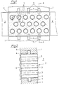
- the concrete segment expansion according to the invention consists of a number of concrete segments 1 with the type of arch or ring expansion, with resilience elements 2 provided between each two concrete segments 1.
- this has a rectangular shape in plan view
- Resilience element made of concrete mortar of a certain composition has a number of pipes 3.
- the number of tubes which are arranged at a distance a from one another and at a distance b from one another is arbitrary and depends only on the required setting force of the resilience element 2.
- the resilience element 2 In the embodiment shown in FIG. 1, three rows with tubes 2 are provided within the resilience element 2, the rows being offset from one another.
- the adjusting force of the resilience element 2 is also dependent on the pipe diameter c and the pipe wall d.
- the resilience element 2 In order to secure the resilience element 2 against pushing movement of the concrete segments 1, the resilience element 2 is provided with pins 4 and the concrete segments 1 with corresponding recesses 5 according to the exemplary embodiments shown in FIGS. 1 and 2.
- the tubes 3 can be filled with fillers, the strength of the Filler depending on the filler entering the tubes 3, and depending on the diameter and the thickness of the tube wall is variable.
Landscapes
- Engineering & Computer Science (AREA)
- Architecture (AREA)
- Structural Engineering (AREA)
- Mining & Mineral Resources (AREA)
- Civil Engineering (AREA)
- Life Sciences & Earth Sciences (AREA)
- General Life Sciences & Earth Sciences (AREA)
- Geochemistry & Mineralogy (AREA)
- Geology (AREA)
- Mechanical Engineering (AREA)
- Lining And Supports For Tunnels (AREA)
Description
- Die Erfindung betrifft einen Betonsegmentausbau für den untertägigen Bergbau und Tunnelbau mit zwischen den Betonsegmenten angeordneten, aus Betonmörtel hergestellten Nachgiebigkeitselementen.
- Die wesentlichen Vorteile des obengenannten Betonsegmentausbaus, insbesondere im untertägigen Bergbau, bestehen in seiner Wirtschaftlichkeit und dem hohen Ausbauwiderstand. Schwierigkeiten bestehen dagegen in der bekannten Weise geringen Verformungsfähigkeit des Betons, der man jedoch mit Hilfe der Verwendung von Nachgiebigkeitselementen abzuhelfen versucht hat.
- Es sind bereits Quetschlagen aus Betonmörtel verschiedener Festigkeiten als Nachgiebigkeitselemente bekannt. Derartige Nachgiebigkeitselemente sind jedoch äusserst empfindlich gegen Schubbewegungen, was die Anwendung in der Firste des untertätigen Streckenausbaus besonders in Frage stellt.
- Neben den obengenannten Nachgiebigkeitselementen aus Betonmörtel sind im Unterfagebergbau Nachgiebigkeitselemente versuchsweise eingesetst worden, die im wesentlichen aus einem zwischen zwei Stahlplatten durch Druck faltbaren rohrartigen Element bestehen. Auch derartige Nachgiebigkeitselemente sind besonders empfindlich gegen Schub und in der Lastaufnahme während der Nachgiebigkeit sehr schwankend.
- Demgegenüber hat sich die Erfindung die Aufgabe gestellt, einen Betonsegmentausbau, insbesondere zur untertätigen Verwendung zu schaffen, der unter Berücksichtigung der dem Betonsegmentausbau eigenen Kriterien, die für den Untertageeinsatz erforderliche einstellbare Nachgiebigkeit mit sich bringt, wobei insbesondere das Nachgiebigkeitselement unanfällig gegen Schubbewegungen der Betonsegmente ist.
- Diese Aufgabe wird erfindungsgemäss dadurch gelöst, dass in den Nachgiebigkeitselementen senkrecht zum Stoss verlaufend Rohre vorgesehen sind.
- Ein besonderer Vorteil der Erfindung ist darin zu sehen, dass die Rohre in den Nachgiebigkeitselementen in Abstand nebeneinander und übereinander angeordnet sind.
- Weiterhin erweist es sich als vorteilhaft im Rahmen der Erfindung, dass die Einstellkraft der Nachgiebigkeitselemente in Abhängigkeit von der Ansprechfestigkeit des Betons, durch die Anzahl der Rohre, durch den Durchmesser und die Rohrwandstärke bestimmbar ist, wobei die Ansprechfähigkeit den Punkt beschreibt, an welchem der Beton zu zerbrechen beginnt.
- Weitere Vorteile der Erfindung sind in den Unteransprüchen näher beschrieben.
- Der technische Fortschritt der Erfindung ist im wesentlichen darin begründet, dass die Elastizität des Ausbaus abstimmbar ist auf die örtlichen Verhältnisse. Die erforderliche Einstellkraft ist durch die Ansprechfestigkeit des Füllmörtels, durch die Rohranzahl, Rohrdurchmesser und Rohrwandstärke beeinflussbar. Beim Überschreiten der vorgegebenen Einstellkraft beginnt das Nachgiebigkeitselement nachzugeben. Dabei bricht zunächst der Verfüllmörtel, anschliessend werden die Rohre verformt bis ca. eine Nachgiebigkeit von 50% der Bauhöhe der Nachgiebigkeitselemente erreicht ist. Die Rohrverformung wird von dem Zerbrechen des Mörtels im immer kleinere Teilchen überlagert, so dass eine Vergleichmässigung der Arbeitskennlinie eintritt.
- Ein Ausführungsbeispiel der Erfindung ist in den Zeichnungen dargestellt und wird im folgenden näher erläutert. Es zeigen :
- Figur 1 eine teilweise Draufsicht des erfindungsgemäßen Betonsegmentausbaus mit einem teilweise geschnitten wiedergegebenen Nachgiebigkeitselement, und
- Figur 2 einen Schnitt nach den Linien A-A in Fig. 1.
- Der erfindungsgemäße Betonsegmentausbau besteht nach Art des Bogen- oder Ringausbaus aus einer Anzahl Betonsegmente 1, mit zwischen jeweils zwei Betonsegmenten 1 vorgesehenen Nachgiebigkeitselementen 2. Wie aus der teilweise wiedergegebenen und geschnittenen Darstellung in Fig. 1 zu entnehmen ist, weist das in der Draufsicht rechteckig geformte Nachgiebigkeitselement aus Betonmörtel bestimmter Zusammensetzung eine Anzahl Rohre 3 auf. Die Anzahl der Rohre die in einem Abstand a voneinander und in einem Abstand b übereinander angeordnet sind, ist beliebig und hängt nur von der geforderten Einstellkraft des Nachgiebigkeitselementes 2 ab.
- In dem in Fig. 1 dargestellten Ausführungsbeispiel sind innerhalb des Nachgiebigkeitselementes 2 drei Reihen mit Rohren 2 vorgesehen wobei die Reihen gegeneinander versetzt angeordnet sind. Die Einstellkraft des Nachgiebigkeitselementes 2 ist weiterhin von dem Rohrdurchmesser c und der Rohrwandung d abhängig. Um eine Sicherung des Nachgiebigkeitselementes 2 gegen Schubbewegung der Betonsegmente 1 zu sichern, ist das Nachgiebigkeitselement 2 nach dem in den Fig. 1 und 2 gezeigten Ausführungsbeispielen mit Zapfen 4 und die Betonsegmente 1 mit entsprechenden Ausnehmungen 5 versehen.
- Um zu vermeiden, daß der durch Druckeinwirkung auf den Ausbau zerbrechende Mörtel von Nachgiebigkeitselementen 2, die in der Firste einer Strecke angeordnet sind, in die Strecke herunterfällt, ist es vorteilhaft, die entsprechenden Nachgiebigkeitselemente 2 mit einer Abdeckplatte 6, beispielsweise einer Wellblechabdeckung zu versehen.
- Zur Erhöhung der Einstellkraft der Nachgiebigkeitselemente 2 können die Rohre 3 mit Füllstoffen verfüllt werden, wobei die Festigkeit des Füllstoffs in Abhängigkeit von den die Rohre 3 eingebenden Füllstoffs, und in Abhängigkeit von Durchmesser und der Stärke der Rohrwandung variierbar ist.

Claims (9)
Applications Claiming Priority (2)
| Application Number | Priority Date | Filing Date | Title |
|---|---|---|---|
| DE3210530 | 1982-03-23 | ||
| DE3210530A DE3210530C2 (de) | 1982-03-23 | 1982-03-23 | Nachgiebiger Betonsegmentausbau |
Publications (2)
| Publication Number | Publication Date |
|---|---|
| EP0089403A1 EP0089403A1 (de) | 1983-09-28 |
| EP0089403B1 true EP0089403B1 (de) | 1985-10-09 |
Family
ID=6159001
Family Applications (1)
| Application Number | Title | Priority Date | Filing Date |
|---|---|---|---|
| EP82110195A Expired EP0089403B1 (de) | 1982-03-23 | 1982-11-05 | Nachgiebiger Betonsegmentausbau |
Country Status (2)
| Country | Link |
|---|---|
| EP (1) | EP0089403B1 (de) |
| DE (2) | DE3210530C2 (de) |
Cited By (1)
| Publication number | Priority date | Publication date | Assignee | Title |
|---|---|---|---|---|
| CN106460510A (zh) * | 2014-05-21 | 2017-02-22 | 建筑机械咨询公司 | 构建隧道的建造元件和包括其的隧道及其构建方法 |
Families Citing this family (15)
| Publication number | Priority date | Publication date | Assignee | Title |
|---|---|---|---|---|
| DE3844776C2 (en) * | 1988-02-26 | 1993-03-11 | Neuero Stahlbau Gmbh & Co., 4520 Melle, De | Roof support for mining gallery |
| DE3806126A1 (de) * | 1988-02-26 | 1989-09-07 | Neuero Stahlbau Gmbh & Co | Geschlossener ausbau fuer insbesondere untertaegige grubenstrecken |
| DE3922047A1 (de) * | 1989-07-05 | 1991-01-10 | Hoesch Ag | Schachtglocke |
| DE4003678A1 (de) * | 1990-02-07 | 1991-08-08 | Neuero Stahlbau Gmbh & Co | Nachgiebigkeitselement |
| DE4133267C2 (de) * | 1991-10-08 | 1994-04-28 | Linsingen Heintzmann Von | Streckenausbau, insbesondere für bergbauliche Untertagebetriebe |
| AT406893B (de) * | 1997-11-28 | 2000-10-25 | Schubert Wulf Dipl Ing Dr | Vorrichtung zum gegenseitigen abstützen zweier segmente einer in umfangsrichtung durch kontraktionsfugen unterteilten tunnelauskleidung |
| EP1564369B1 (de) * | 2004-02-16 | 2007-12-12 | Kalman Prof. Dr. Kovari | Verfahren und Einrichtung zum Stabilisieren eines beim Untertagebau ausgebrochenen Hohlraumes |
| WO2006034675A1 (de) * | 2004-09-29 | 2006-04-06 | Kloeckner Reinhard | Kompressibler beton und verfahren zu dessen herstellung |
| DE502005006010D1 (de) * | 2005-09-08 | 2009-01-02 | Amberg Engineering Ag | Nachgiebigkeitselement für einen Untertageraum |
| EP2042686B1 (de) * | 2007-09-27 | 2009-07-08 | Bochumer Eisenhütte Heintzmann GmbH & Co. KG | Nachgiebigkeitselement |
| DE102009057521B4 (de) * | 2009-12-10 | 2011-07-21 | Bochumer Eisenhütte Heintzmann GmbH & Co. KG, 44793 | Tübbing-Ausbau mit integriertem Nachgiebigkeitselement |
| DE202010013454U1 (de) | 2010-09-23 | 2010-11-25 | Bochumer Eisenhütte Heintzmann GmbH & Co. KG | Stützausbau für Tunnelbauwerke |
| US8851805B2 (en) | 2012-08-30 | 2014-10-07 | Burrell Mining Products, Inc. | Telescopic mine roof support |
| US9611738B2 (en) * | 2014-08-27 | 2017-04-04 | Burrell Mining Products, Inc. | Ventilated mine roof support |
| US9903203B2 (en) | 2014-08-27 | 2018-02-27 | Burrell Mining Products, Inc. | Ventilated mine roof support |
Family Cites Families (7)
| Publication number | Priority date | Publication date | Assignee | Title |
|---|---|---|---|---|
| DE369695C (de) * | 1923-07-31 | Karl Walter Dipl Ing | Eisenbeton-Stollenausbau | |
| DE301200C (de) * | ||||
| FR593877A (fr) * | 1923-12-17 | 1925-09-01 | Revêtement flexible de mines | |
| AT117579B (de) * | 1927-11-25 | 1930-04-25 | Karl Dr Ing Kabelac | Einrichtung zum Abdichten von durch Tragkörper ausgebauten Grubenräumen von kreisförmigem oder ähnlichem Querschnitt. |
| DE2101092C3 (de) * | 1971-01-12 | 1978-04-20 | Hans Otto Dr.-Ing. 4370 Marl Luetgendorf | Bogenförmiger Streckenausbau mit Hilfe von Segmenten aus Beton |
| DE2510912C3 (de) * | 1975-03-13 | 1980-01-03 | Bauunternehmung E. Heitkamp Gmbh, 4690 Herne | Verfahren zum Errichten der Auskleidung eines Bunkers, insbesondere im Untertagebergbau und Vorrichtung zur Durchführung des Verfahrens |
| NL7904287A (nl) * | 1979-05-31 | 1980-12-02 | Johannes Petrus Antonius Roest | Werkwijze voor het ondersteunen van mijngangen en dergelijke volgens deze werkwijze ingerichte mijngang of dergelijke. |
-
1982
- 1982-03-23 DE DE3210530A patent/DE3210530C2/de not_active Expired
- 1982-11-05 EP EP82110195A patent/EP0089403B1/de not_active Expired
- 1982-11-05 DE DE8282110195T patent/DE3266863D1/de not_active Expired
Cited By (2)
| Publication number | Priority date | Publication date | Assignee | Title |
|---|---|---|---|---|
| CN106460510A (zh) * | 2014-05-21 | 2017-02-22 | 建筑机械咨询公司 | 构建隧道的建造元件和包括其的隧道及其构建方法 |
| CN106460510B (zh) * | 2014-05-21 | 2020-09-15 | 建筑机械咨询公司 | 构建隧道的建造元件和包括其的隧道及其构建方法 |
Also Published As
| Publication number | Publication date |
|---|---|
| DE3266863D1 (en) | 1985-11-14 |
| DE3210530A1 (de) | 1983-10-13 |
| DE3210530C2 (de) | 1984-01-05 |
| EP0089403A1 (de) | 1983-09-28 |
Similar Documents
| Publication | Publication Date | Title |
|---|---|---|
| EP0089403B1 (de) | Nachgiebiger Betonsegmentausbau | |
| DE69736232T2 (de) | Schraubverbindung für ölfeldrohre | |
| EP1165905B1 (de) | Kunststoffplatte, insbesondere zum auskleiden von betonbauteilen | |
| DE2752032A1 (de) | Drahtankerhalterung | |
| DE3210529C1 (de) | Nachgiebiger Betonsegmentausbau | |
| CH682101A5 (de) | ||
| DE2648477C3 (de) | Verbundausbau für Bergbauschächte | |
| DE2306401A1 (de) | Bausatz fuer eine tunnelauskleidung | |
| AT368603B (de) | Fachwerkrahmen, vorzugsweise ausbaurahmen fuer stollen, tunnel od. dgl. | |
| DE2435559A1 (de) | Tuebbing fuer tunnel- und schachtausbau | |
| DE2107402A1 (de) | Betondecken-Bauelement | |
| DE2912989C2 (de) | Ringausbau für am vorläufig verfestigten, vorzugsweise im gefrorenen Gebirge abgeteufte Schächte des Berg- und Tunnelbaus | |
| DE852147C (de) | Rand- oder Eckwinkel einer Stahlschalung | |
| DE3105743A1 (de) | Tuebbing mit selbstverriegelndem verbindungselement fuer den ausbau von tunneln und schaechten | |
| AT345328B (de) | Mehrkammeriges gummihohlprofil | |
| DE10313305A1 (de) | Futterrohr zur Rohrdurchführung | |
| DE965965C (de) | Nachgiebiger Schachtausbau | |
| DE919522C (de) | Ringausbau fuer Schaechte, insbesondere Blindschaechte, Gesenke u. dgl. und Verfahren zu seiner Herstellung | |
| CH697312B1 (de) | Lastübertragungseinrichtung für Schachtbauteile. | |
| DD287299A5 (de) | Schalung fuer erdstoffumhuellte betonbauteile | |
| DE60109766T2 (de) | Mauerwerksanker | |
| DE3307230A1 (de) | Grubenausbauprofil fuer formschluessigen anschluss | |
| AT5770U1 (de) | Fugendichtungsprofil für betondecken von verkehrsflächen | |
| DE1120402B (de) | Doppel-Tuebbing-Schachtausbau | |
| DE7916007U1 (de) | Befestigungselement mit Ankerbolzen und Spreizkeil |
Legal Events
| Date | Code | Title | Description |
|---|---|---|---|
| PUAI | Public reference made under article 153(3) epc to a published international application that has entered the european phase |
Free format text: ORIGINAL CODE: 0009012 |
|
| AK | Designated contracting states |
Designated state(s): BE DE FR GB |
|
| 17P | Request for examination filed |
Effective date: 19830803 |
|
| R17P | Request for examination filed (corrected) |
Effective date: 19830903 |
|
| GRAA | (expected) grant |
Free format text: ORIGINAL CODE: 0009210 |
|
| AK | Designated contracting states |
Designated state(s): BE DE FR GB |
|
| ET | Fr: translation filed | ||
| REF | Corresponds to: |
Ref document number: 3266863 Country of ref document: DE Date of ref document: 19851114 |
|
| PLBE | No opposition filed within time limit |
Free format text: ORIGINAL CODE: 0009261 |
|
| STAA | Information on the status of an ep patent application or granted ep patent |
Free format text: STATUS: NO OPPOSITION FILED WITHIN TIME LIMIT |
|
| 26N | No opposition filed | ||
| PGFP | Annual fee paid to national office [announced via postgrant information from national office to epo] |
Ref country code: DE Payment date: 19951023 Year of fee payment: 14 |
|
| PGFP | Annual fee paid to national office [announced via postgrant information from national office to epo] |
Ref country code: FR Payment date: 19961010 Year of fee payment: 15 |
|
| PGFP | Annual fee paid to national office [announced via postgrant information from national office to epo] |
Ref country code: BE Payment date: 19961021 Year of fee payment: 15 |
|
| PGFP | Annual fee paid to national office [announced via postgrant information from national office to epo] |
Ref country code: GB Payment date: 19961022 Year of fee payment: 15 |
|
| PG25 | Lapsed in a contracting state [announced via postgrant information from national office to epo] |
Ref country code: DE Effective date: 19970801 |
|
| PG25 | Lapsed in a contracting state [announced via postgrant information from national office to epo] |
Ref country code: GB Free format text: LAPSE BECAUSE OF NON-PAYMENT OF DUE FEES Effective date: 19971105 |
|
| PG25 | Lapsed in a contracting state [announced via postgrant information from national office to epo] |
Ref country code: FR Free format text: THE PATENT HAS BEEN ANNULLED BY A DECISION OF A NATIONAL AUTHORITY Effective date: 19971130 Ref country code: BE Free format text: LAPSE BECAUSE OF NON-PAYMENT OF DUE FEES Effective date: 19971130 |
|
| BERE | Be: lapsed |
Owner name: BERGWERKSVERBAND G.M.B.H. Effective date: 19971130 |
|
| GBPC | Gb: european patent ceased through non-payment of renewal fee |
Effective date: 19971105 |
|
| REG | Reference to a national code |
Ref country code: FR Ref legal event code: ST |