EP0087584A2 - Vorrichtung zur Herstellung von Presskörpern - Google Patents
Vorrichtung zur Herstellung von Presskörpern Download PDFInfo
- Publication number
- EP0087584A2 EP0087584A2 EP83100736A EP83100736A EP0087584A2 EP 0087584 A2 EP0087584 A2 EP 0087584A2 EP 83100736 A EP83100736 A EP 83100736A EP 83100736 A EP83100736 A EP 83100736A EP 0087584 A2 EP0087584 A2 EP 0087584A2
- Authority
- EP
- European Patent Office
- Prior art keywords
- upper punch
- outlet opening
- sleeve
- valve flap
- pressing process
- Prior art date
- Legal status (The legal status is an assumption and is not a legal conclusion. Google has not performed a legal analysis and makes no representation as to the accuracy of the status listed.)
- Granted
Links
Images
Classifications
-
- B—PERFORMING OPERATIONS; TRANSPORTING
- B30—PRESSES
- B30B—PRESSES IN GENERAL
- B30B15/00—Details of, or accessories for, presses; Auxiliary measures in connection with pressing
- B30B15/06—Platens or press rams
- B30B15/065—Press rams
-
- B—PERFORMING OPERATIONS; TRANSPORTING
- B30—PRESSES
- B30B—PRESSES IN GENERAL
- B30B15/00—Details of, or accessories for, presses; Auxiliary measures in connection with pressing
- B30B15/0005—Details of, or accessories for, presses; Auxiliary measures in connection with pressing for briquetting presses
- B30B15/0017—Deairing means
-
- C—CHEMISTRY; METALLURGY
- C06—EXPLOSIVES; MATCHES
- C06B—EXPLOSIVES OR THERMIC COMPOSITIONS; MANUFACTURE THEREOF; USE OF SINGLE SUBSTANCES AS EXPLOSIVES
- C06B21/00—Apparatus or methods for working-up explosives, e.g. forming, cutting, drying
- C06B21/0033—Shaping the mixture
- C06B21/0041—Shaping the mixture by compression
-
- Y—GENERAL TAGGING OF NEW TECHNOLOGICAL DEVELOPMENTS; GENERAL TAGGING OF CROSS-SECTIONAL TECHNOLOGIES SPANNING OVER SEVERAL SECTIONS OF THE IPC; TECHNICAL SUBJECTS COVERED BY FORMER USPC CROSS-REFERENCE ART COLLECTIONS [XRACs] AND DIGESTS
- Y10—TECHNICAL SUBJECTS COVERED BY FORMER USPC
- Y10S—TECHNICAL SUBJECTS COVERED BY FORMER USPC CROSS-REFERENCE ART COLLECTIONS [XRACs] AND DIGESTS
- Y10S425/00—Plastic article or earthenware shaping or treating: apparatus
- Y10S425/812—Venting
Definitions
- the invention relates to a device for the production of compacts, in particular compacts consisting of explosives, according to the preamble of patent claim 1.
- Radial bores of the type described above are particularly not applicable even if the material to be pressed is to be processed warm and the material to be heated is spread in a widespread manner, for example by a heating liquid surrounding the die or the press pot.
- the invention has for its object to provide a device for the production of compacts, in particular compacts consisting of explosives, which are characterized by a characterized by inexpensive construction and which allows the production of non-porous compacts while maintaining safe conditions.
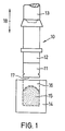
- Fig. 1 shows a schematic representation of the essential for the invention parts of the above-mentioned device, which cooperate during the pressing process. Shown is an upper punch 10 which can be moved up and down in the direction of the double arrow 18 and, during its downward movement, is immersed in a stationary die (press pot) 14 which contains the material to be pressed 15. The remaining parts of the device, in particular the means for holding the die 14 and the upper punch 10 and the means for moving it, are not shown in FIG. 1, since they are irrelevant for the explanation of the invention.
- the upper punch 10 comprises at least one gas outlet opening which at least temporarily connects the pressing volume 16 to the surroundings even after the upper punch 10 has been immersed in the die 14, and which Displacement of the gas components can be closed automatically by shut-off means.
- the gas outlet opening consists of a central axial bore 20, 20 'penetrating the upper punch 10, which is arranged with a central part 12 of the first punch 10 in essentially radially extending connecting channel 21 is connected.
- the inner wall 25 of this pot-shaped sleeve 11 comprises a stair-shaped peripheral seat 25 which lies in a plane perpendicular to the longitudinal axis of the upper punch 10. This seat 25 serves as a stop for the thread 23 of the part 12.
- the seat 25 delimits a partial volume 26 of the sleeve 11 upwards, in which shut-off means for closing the bore 20 are arranged.
- shut-off means consist of a valve flap 40 (FIG. 4) which rests on the bottom of the sleeve 11 in the idle state and which in the partial volume 26 of the sleeve 11 which is limited by the seat 25 in the axial direction up to the stop on the end face of the upper punch part 12 is free to move.
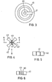
- the valve flap 40 consists of a hub 41, which, for centering purposes, has projections 42 which are evenly spaced around the circumference and extend in the radial direction.
- FIGS. 5 and 6 show a side view of the valve flap 40 with viewing direction B according to FIG. 4.
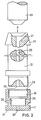
- FIG. 6 is a sectional view through the valve flap 40 along the line 6 - 6 from FIG. 4 Fig. Provides a view from viewing direction A acc. Fig. 2 on the top of the middle part 12 of the upper punch 10 and is understandable in itself without further explanation.
- the valve flap 40 is expediently made of a plastic, for example Makrolon.
- the operation of the device according to the invention is as follows. After filling the pressed material 15 into the die 14, the upper punch 10 moves into the pressing volume 16 and begins to displace the gas components contained in the pressing volume 16 through the bore 20) 20 and the connecting channel 21 to the outside. At this time, the valve flap% 0 rests on the bottom of the sleeve 11. As soon as the upper punch 10 comes into contact with the pressed material 15 during further lowering, a small proportion of the pressed material 15 enters the inside of the sleeve 11 through the bore 20 'which penetrates the bottom 17 of the cup-shaped sleeve 11 and thereby lifts the valve flap 40 from the bottom the sleeve 11 from.
- valve flap 40 is then pressed against the bore 20 opening in the central part 12 of the upper punch 10 and closes it.
- the gas outlet opening which initially exists via the bore 20 and the connecting channel 21 is closed and prevents material to be pressed from entering the bore 20 arranged in the central part 12 of the upper punch 10.
- the upper piston 10 After the pressing process has ended, the upper piston 10 returns in the upward direction of the double arrow 18 (FIG. 1), only the uppermost part 13 of the upper piston 10 taking part in this movement.
- the interconnected parts 11 and 12 of the upper piston 10 may remain in the die 14 until the material to be cooled has cooled down and can be removed together with the latter until the pressed part is removed from the device.
- the small amount of pressed material that has entered the sleeve 11 can be removed in a simple manner by a suitable solvent, for example warm water; the sleeve 11 can then be used for a new pressing process.
- a suitable solvent for example warm water
- the parts identified by reference numerals 11, 12 and 13 can also be designed to be retractable together.
Landscapes
- Engineering & Computer Science (AREA)
- Mechanical Engineering (AREA)
- Chemical & Material Sciences (AREA)
- Organic Chemistry (AREA)
- Pens And Brushes (AREA)
- Electrical Discharge Machining, Electrochemical Machining, And Combined Machining (AREA)
- Filling Or Discharging Of Gas Storage Vessels (AREA)
- Forging (AREA)
- Casting Or Compression Moulding Of Plastics Or The Like (AREA)
- Powder Metallurgy (AREA)
Abstract
Description
- Die Erfindung betrifft eine Vorrichtung zur Herstellung von Preßkörpern,insbesondere aus Explosivstoff bestehenden Preßkörpern nach dem Oberbegriff des Patentanspruchs 1.
- Es ist allgemein bekannt, daß die Herstellung von Preßkörpern sowohl im Strang-als auch im Blockpreßverfahren mit Mängeln behaftet ist, die insbesondere darin bestehen, daß der in den Preßzylinder bzw. Preßtopf einfahrende Preßstempel eine Kompression der im Preßvolumen gegebenenfalls vorhandenen Gasanteile (Luft) zur Folge hat. Diese Kompression kann sich auf unterschiedliche Art und Weise unangenehm bemerkbar machen. Zunächst wird die eingeschlossene Luft über dem Preßgut infolge adiabatischer Verdichtung erhitzt. Dies kann Entzündung und Zersetzung des zu verdichtenden Preßguts zur Folge haben. In einem weniger ungünstigen Fall wird die komprimierte und erhitzte Luft vom niedergehenden Preßstempel in das Preßgut gedrückt und gestaltet das Ausgangsprodukt porös, was ebenfalls unerwünscht ist.
- Es wurde bereits versucht, die während des Preßvorgangs zwangsläufig entstehende Kompression vorhandener Gasanteile dadurch zu verhindern, daß im Bereich des Preßtopfs oder der Matrize radial verlaufende Bohrungen angebracht wurden, die eine Verbindung des Preßvolumens mit der Umgebung herstellten und ein Entweichen der Luft ermöglichen sollten. Diese bekannte Lösung ist jedoch nicht zufriedenstellend, da aufgrund unterschiedlicher Schütthöhen verschiedenartigen Preßguts ein Sicherheitsabstand zwischen dem Niveau der Radialbohrungen und der Oberfläche des eingefüllten Preßguts in Kauf zu nehmen war, um während des Preßvorgangs ein Verstopfen der Entlüftungsöffnungen zu verhindern. Dadurch verblieb zwischen dem einfahrenden Preßstempel und dem Preßgut eine Restluftmenge, die weiterhin zu den eingangs beschriebenen nachteiligen Folgen führte.
- Radialbohrungen der vorbeschriebenen Art sind insbesondere auch dann nicht anwendbar, wenn das Preßgut warm zu verarbeiten ist und die Erwärmung des Preßguts auf weitverbreitete Weise, beispielsweise durch eine die Matrize oder den Preßtopf umgebende Heizflüssigkeit erfolgt.
- Es wurde auch schon versucht, zur Beseitigung von im Preßvolumen vorhandenen Gasanteilen,das Preßgut unter Vakuumbedingungen zu verdichten. Dafür geeignete Vorrichtungen sind jedoch sehr aufwendig, da sie zumindest eine Vakuumpumpe, Dichtungsmanschetten, Abscheider mit Reinigungsmöglichkeiten und die vorerwähnten Bauelemente verbindende Rohrleitungssysteme umfassen. Neben dem apparativen Aufwand verlängern sich die Preßzeiten, da vor Beginn des Preßvorgangs jeweils erst Vakuumbedingungen herzustellen sind.
- Der Erfindung liegt die Aufgabe zugrunde, eine Vorrichtung zur Herstellung von Preßkörpern,insbesondere aus Explosivstoff bestehenden Preßkörpern anzugeben, die sich durch eine preiswerte Konstruktion auszeichnet und die bei Einhaltung sicherer Bedingungen die Herstellung nichtporöser Preßkörper ermöglicht.
- Ausgehend von einer Vorrichtung der eingangs genannten Art wird diese Aufgabe durch die in Patentanspruch 1 angegebene Erfindung gelöst.
- Vorteilhafte Ausgestaltungen dieser Vorrichtung gehen aus den Unteransprüchen hervor.
- Die Erfindung wird nachfolgend unter Bezug auf die Zeichnung näher erläutert. Dabei zeigt:
- Fig. 1: eine schematische Darstellung von beim Preßvorgang zusammenwirkenden Teilen der Vorrichtung;
- Fig. 2: eine vergrößerte, z. T. im Schnitt dargestellte Seitenansicht des Oberstempels der Vorrichtung;
- Fig. 3: eine Aufsicht auf den mittleren Teil des aus mehreren Teilen bestehenden Oberstempels mit Blickrichtung aus Richtung A gem. Fig. 2;
- Fig. 4: eine Aufsicht auf die im unteren Teil des mehrteiligen Oberstempels angeordnete Ventilklappe;
- Fig. 5: eine Seitenansicht aus Blickrichtung B der in Fig. 4 dargestellten Ventilklappe;
- Fig. 6: eine Schnittdarstellung der Ventilklappe gemäß Linie 6 - 6 aus Fig. 4.
- Fig. 1 zeigt eine schematische Darstellung der für die Erfindung wesentlichen Teile der eingangs erwähnten Vorrichtung, die während des Preßvorgangs zusammenwirken. Dargestellt ist ein in Richtung des Doppelpfeils 18 auf- und abbewegbarer Oberstempel 10, der während seiner Abwärtsbewegung in eine das zu verpressende Preßgut 15 enthaltende ortsfest angeordnete Matrize (Preßtopf) 14 eintaucht. Die übrigen Teile der Vorrichtung, insbesondere die Mittel zur Halterung der Matrize 14 und des Oberstempels 10 und die Mittel zu dessen Fortbewegung sind in Fig. 1 nicht dargestellt, da sie für die Erläuterung der Erfindung ohne Belang sind.
- Um während des Preßvorgangs eine Ableitung der ggf. im Preßvolumen 16 enthaltenen Gasanteile zu ermöglichen, umfaßt der Oberstempel 10 mindestens eine Gasaustrittsöffnung, die zumindest zeitweilig das Preßvolumen 16 auch noch nach dem Eintauchen des Oberstempels 10 in die Matrize 14 mit der Umgebung verbindet und die nach Verdrängen der Gasanteile durch Absperrmittel selbsttätig verschließbar ist.
- Wie aus Fig. 2 ersichtlich ist, die eine vergrößerte Darstellung des aus mehreren Teilen bestehenden Oberstempels 10 wiedergibt, besteht die Gasaustrittsöffnung aus einer den Oberstempel 10 durchsetzenden zentralaxialen Bohrung 20, 20', die mit einem im mittleren Teil 12 des erstempels 10 angeordneten, im wesentlichen radial verlaufenden Verbindungskanal 21 verbunden ist. Dadurch ist sichergestellt, daß auch bei aufgesetztem Oberteil 13 des Oberstempels 10, der über den in Fig. 2 dargestellten Konus mit dem mittleren Teil 12 des Oberstempels 10 zentrierbar ist, die Gasanteile aus dem Preßvolumen 16 über die Bohrung 20, 20' und den Verbindungskanal 21 in die Umgebung entweichen können.
- Die von der zentralaxialen Bohrung 20, 20' durchsetzten Teile-11, 12 des mehrteiligen Oberstempels 10 umfassen eine mit ihrer äußeren Bodenfläche 17 auf das Preßgut 15 einwirkende topfförmig ausgebildete Hülse 11, die mit dem den radial verlaufenden Verbindungskanal 21 enthaltenden Teilstück 12 des Oberstempels 10 lösbar, insbesondere mittels einer Verschraubung 23 verbindbar ist. Die Innenwandung 25 dieser topfförmigen Hülse 11 umfaßt einen treppenförmig ausgebildeten umlaufenden Sitz 25, der in einer senkrecht auf der Längsachse des Oberstempels 10 stehenden Ebene liegt. Dieser Sitz 25 dient als Anschlag für das Gewinde 23 des Teils 12. Der Sitz 25 begrenzt ein Teilvolumen 26 der Hülse 11 nach oben, in dem Absperrmittel zum Verschließen der Bohrung 20 angeordnet sind. Diese Absperrmittel bestehen aus einer Ventilklappe 40 (Fig. 4), die im Ruhezustand auf dem Boden der Hülse 11 aufliegt und die in dem durch-den Sitz 25 nach oben begrenzten Teilvolumen 26 der Hülse 11 in Axialrichtung bis zum Anschlag an die Stirnfläche des Oberstempelteils 12 frei beweglich ist. Die Ventilklappe 40 besteht in einem bevorzugten Ausführungsbeispiel der Erfindung aus einer Nabe 41, die zur Zentrierung auf dem Umfang gleichmäßig beabstandet angeordnete, in Radialrichtung sich erstreckende Fortsätze 42 trägt. In eine Stirnfläche 60 der Nabe 41 der Ventilklappe 40 sind entlang sich kreuzender Durchmesser Nuten 43, 43' eingebracht, die ein Entweichen der Gasanteile begünstigen. Die spezielle Gestalt der Ventilklappe 40 und die Anordnung der Nuten geht auch aus den Fig. 5 und 6 hervor. Fig. 5 zeigt dabei eine Seitenansicht der Ventilklappe 40 mit Blickrichtung B gemäß Fig. 4 Fig. 6 ist eine Schnittdarstellung durch die Ventilklappe 40 entlang der Linie 6 - 6 aus Fig. 4 Fig. stellt eine Ansicht aus Blickrichtung A gem. Fig. 2 auf die Oberseite des mittleren Teils 12 des Oberstempels 10 dar und ist aus sich heraus ohne weitere Erläuterung verständlich.
- Die Ventilklappe 40 wird zweckmäßig aus einem Kunststoff, beispielsweise Makrolon hergestellt.
- Die Wirkungsweise der erfindungsgemäßen Vorrichtung ist wie folgt. Nach Einfüllen des Preßguts 15 in die Matrize 14 fährt der Oberstempel 10 in das Preßvolumen 16 ein und beginnt die im Preßvolumen 16 enthaltenen Gasanteile durch die Bohrung 20) 20 und den Verbindungskanal 21 nach außen zu verdrängen. Zu diesem Zeitpunkt -liegt die Ventilklappe %0 auf dem Boden der Hülse 11 auf. Sobald der Oberstempel 10 beim weiteren Absenken mit dem Preßgut 15 in Berührung kommt, tritt ein geringer Anteil des Preßguts 15 durch die den Boden 17 der topfförmigen Hülse 11 durchsetzende Bohrung 20' in das Innere der Hülse 11 ein und hebt dabei die Ventilklappe 40 vom Boden der Hülse 11 ab. Die Ventilklappe 40 wird dann gegen die im mittleren Teil 12 des Oberstempels 10 mündende Bohrung 20 gepreßt und verschließt diese. Dadurch wird die zunächst über die Bohrung 20 und den Verbindungskanal 21 bestehende Gasaustrittsöffnung verschlossen und verhindert, daß Preßgut in die im mittleren Teil 12 des Oberstempels 10 angeordnete Bohrung 20 eintritt.
- Nach Beendung des Preßvorgangs kehrt der Oberkolben 10 in Aufwärtsrichtung des Doppelpfeils 18 (Fig. 1) zurück, wobei an dieser Bewegung allerdings nur der oberste Teil 13 des Oberkolbens 10 teilnimmt. Die miteinander verbundenen Teile 11 und 12 des Oberkolbens 10 verbleiben ggf. bis zum Abkühlen des Preßguts in der Matrize 14 und können zusammen mit dieser bis zur Entnahme des Preßteils aus der Vorrichtung entnommen werden.
- Die in die Hülse 11 eingetretene geringe Preßgutmenge kann auf einfache Weise durch ein geeignetes Lösungsmittel, beispielsweise warmes Wasser, entfernt werden; die Hülse 11 ist daraufhin für einen neuen Preßvorgang verwendbar.
- In einem weiteren Ausführungsbeispiel der Erfindung können die mit Bezugsziffern 11, 12 und 13 bezeichneten Teile auch gemeinsam zurückziehbar ausgebildet sein.
Claims (9)
Applications Claiming Priority (2)
| Application Number | Priority Date | Filing Date | Title |
|---|---|---|---|
| DE3207191 | 1982-02-27 | ||
| DE19823207191 DE3207191A1 (de) | 1982-02-27 | 1982-02-27 | Vorrichtung zur herstellung von presskoerpern |
Publications (3)
| Publication Number | Publication Date |
|---|---|
| EP0087584A2 true EP0087584A2 (de) | 1983-09-07 |
| EP0087584A3 EP0087584A3 (en) | 1985-04-24 |
| EP0087584B1 EP0087584B1 (de) | 1987-01-07 |
Family
ID=6156934
Family Applications (1)
| Application Number | Title | Priority Date | Filing Date |
|---|---|---|---|
| EP83100736A Expired EP0087584B1 (de) | 1982-02-27 | 1983-01-27 | Vorrichtung zur Herstellung von Presskörpern |
Country Status (4)
| Country | Link |
|---|---|
| US (1) | US4545755A (de) |
| EP (1) | EP0087584B1 (de) |
| DE (2) | DE3207191A1 (de) |
| NO (1) | NO155651C (de) |
Families Citing this family (5)
| Publication number | Priority date | Publication date | Assignee | Title |
|---|---|---|---|---|
| SE460460B (sv) * | 1983-07-01 | 1989-10-16 | Convey Teknik Ab | Foerfarande och anordning foer reglerad pressning av pulvermaterial |
| JPH0636076B2 (ja) * | 1985-04-12 | 1994-05-11 | 株式会社日立製作所 | 放射性廃棄物の造粒装置 |
| DE3523930A1 (de) * | 1985-07-04 | 1987-01-08 | Dynamit Nobel Ag | Schutzverfahren beim umhuellen von temperatur- bzw. druckempfindlichen stoffen |
| US5549769A (en) * | 1989-03-20 | 1996-08-27 | Breed Automotive Technology, Inc. | High temperature stable, low imput energy primer/detonator |
| DE102012104202A1 (de) * | 2012-05-15 | 2013-11-21 | CONAPRO GmbH | Vorrichtung zur Herstellung von Betonprodukten |
Family Cites Families (8)
| Publication number | Priority date | Publication date | Assignee | Title |
|---|---|---|---|---|
| DE174347C (de) * | ||||
| US1826945A (en) * | 1928-02-06 | 1931-10-13 | American Container Corp | Molding apparatus |
| DE556298C (de) * | 1931-02-25 | 1932-08-06 | Becker & Van Huellen | Hydraulische Presse |
| GB508598A (en) * | 1938-02-18 | 1939-07-04 | Horace Harrison Macey | Improved press for moulding powdered material |
| US2607435A (en) * | 1949-08-08 | 1952-08-19 | Dohse Hans | Apparatus for increasing the bulk density of pulverulent materials |
| US2865052A (en) * | 1955-10-04 | 1958-12-23 | Hooker Chemical Corp | Vented mold for plastic materials |
| US3377662A (en) * | 1965-04-20 | 1968-04-16 | Bridgestone Tire Co Ltd | Metal mold having vent plug means for shaping a plastic article and vulcanizing a rubber article |
| US3822857A (en) * | 1971-02-16 | 1974-07-09 | Toyo Tire & Rubber Co | Synthetic resin plug for vent hole of mould |
-
1982
- 1982-02-27 DE DE19823207191 patent/DE3207191A1/de not_active Withdrawn
-
1983
- 1983-01-27 EP EP83100736A patent/EP0087584B1/de not_active Expired
- 1983-01-27 DE DE8383100736T patent/DE3368918D1/de not_active Expired
- 1983-02-22 NO NO830605A patent/NO155651C/no unknown
- 1983-02-28 US US06/470,598 patent/US4545755A/en not_active Expired - Fee Related
Also Published As
| Publication number | Publication date |
|---|---|
| DE3207191A1 (de) | 1983-09-08 |
| NO155651B (no) | 1987-01-26 |
| EP0087584B1 (de) | 1987-01-07 |
| US4545755A (en) | 1985-10-08 |
| DE3368918D1 (en) | 1987-02-12 |
| NO155651C (no) | 1987-05-06 |
| NO830605L (no) | 1983-08-29 |
| EP0087584A3 (en) | 1985-04-24 |
Similar Documents
| Publication | Publication Date | Title |
|---|---|---|
| DE69013883T2 (de) | Pumpenanordnung. | |
| DE69203591T2 (de) | In umgekehrter Lage verwendbares Dosierventil. | |
| DE2353209A1 (de) | Tiefgezogener behaelter und verfahren zu seiner herstellung | |
| DE1458259A1 (de) | Kompaktierpresse | |
| DE1653419A1 (de) | Fluessigkeitsabgabepumpe | |
| DE3145742A1 (de) | Entgasungsvorrichtung fuer eine gussform, insbesondere spritzgussform | |
| DE2163584A1 (de) | Probenbehälter- und Verschlußkappenaggregat für einen Zentrifugenrotor | |
| DE2356398A1 (de) | Thermisch betaetigte berst-scheibe | |
| DE2200730A1 (de) | Vielfachverteiler fuer eine Fluessigkeit | |
| DE2912471C2 (de) | ||
| DE2242067B2 (de) | Längenverstellbarer Pleuel für eine Presse mit hydraulischer Überlastsicherung | |
| EP0087584A2 (de) | Vorrichtung zur Herstellung von Presskörpern | |
| DE1956551A1 (de) | Presswerkzeug fuer die Herstellung von Stangen und Rohren durch Pressen von Pulver | |
| DE2144071A1 (de) | Vorrichtung zur Herstellung von Presslingen aus einem pulverförmigen Material | |
| DE2704832B1 (de) | Kolbenstrangpresse zum Auspressen plastischer Massen | |
| DE2816931C3 (de) | Vorrichtung an einem Druckzyklon | |
| DE2840008A1 (de) | Entspannungsventilanordnung | |
| DE540651C (de) | Fluessigkeits-Stossdaempfer | |
| DE2202258B2 (de) | Vorrichtung zur stoßfreien Durchflußregelung | |
| DE2756670C2 (de) | Verfahren und Vorrichtung zur Heißformung zweibasiger Propergolblöcke | |
| DE1961265A1 (de) | Verfahren und Vorrichtung zur Verformung von Materialien | |
| DE2315029A1 (de) | Pressenkopf | |
| DE4407299C1 (de) | Vorrichtung zur Herstellung von hohlzylindrischen Produkten | |
| DE69503232T2 (de) | Vorrichtung zur einstellung des druckkammervolumens einer vordruckpumpe | |
| DE4000459A1 (de) | Vorrichtung zur entnahme und speicherung von proben von lagerstaettenfluiden |
Legal Events
| Date | Code | Title | Description |
|---|---|---|---|
| PUAI | Public reference made under article 153(3) epc to a published international application that has entered the european phase |
Free format text: ORIGINAL CODE: 0009012 |
|
| AK | Designated contracting states |
Designated state(s): BE DE FR GB IT NL SE |
|
| PUAL | Search report despatched |
Free format text: ORIGINAL CODE: 0009013 |
|
| AK | Designated contracting states |
Designated state(s): BE DE FR GB IT NL SE |
|
| 17P | Request for examination filed |
Effective date: 19850223 |
|
| 17Q | First examination report despatched |
Effective date: 19860214 |
|
| GRAA | (expected) grant |
Free format text: ORIGINAL CODE: 0009210 |
|
| ITF | It: translation for a ep patent filed | ||
| AK | Designated contracting states |
Kind code of ref document: B1 Designated state(s): BE DE FR GB IT NL SE |
|
| PGFP | Annual fee paid to national office [announced via postgrant information from national office to epo] |
Ref country code: NL Payment date: 19870131 Year of fee payment: 5 |
|
| REF | Corresponds to: |
Ref document number: 3368918 Country of ref document: DE Date of ref document: 19870212 |
|
| ET | Fr: translation filed | ||
| PLBE | No opposition filed within time limit |
Free format text: ORIGINAL CODE: 0009261 |
|
| STAA | Information on the status of an ep patent application or granted ep patent |
Free format text: STATUS: NO OPPOSITION FILED WITHIN TIME LIMIT |
|
| 26N | No opposition filed | ||
| PG25 | Lapsed in a contracting state [announced via postgrant information from national office to epo] |
Ref country code: GB Effective date: 19890127 |
|
| PG25 | Lapsed in a contracting state [announced via postgrant information from national office to epo] |
Ref country code: SE Effective date: 19890128 |
|
| PG25 | Lapsed in a contracting state [announced via postgrant information from national office to epo] |
Ref country code: BE Effective date: 19890131 |
|
| BERE | Be: lapsed |
Owner name: RHEINMETALL G.M.B.H. Effective date: 19890131 |
|
| PG25 | Lapsed in a contracting state [announced via postgrant information from national office to epo] |
Ref country code: NL Effective date: 19890801 |
|
| NLV4 | Nl: lapsed or anulled due to non-payment of the annual fee | ||
| GBPC | Gb: european patent ceased through non-payment of renewal fee | ||
| PG25 | Lapsed in a contracting state [announced via postgrant information from national office to epo] |
Ref country code: FR Free format text: LAPSE BECAUSE OF NON-PAYMENT OF DUE FEES Effective date: 19890929 |
|
| REG | Reference to a national code |
Ref country code: FR Ref legal event code: ST |
|
| PGFP | Annual fee paid to national office [announced via postgrant information from national office to epo] |
Ref country code: DE Payment date: 19891206 Year of fee payment: 8 |
|
| PG25 | Lapsed in a contracting state [announced via postgrant information from national office to epo] |
Ref country code: DE Effective date: 19911001 |
|
| EUG | Se: european patent has lapsed |
Ref document number: 83100736.4 Effective date: 19891204 |