EP0083752A2 - Boucle pour ceintures de sécurité - Google Patents
Boucle pour ceintures de sécurité Download PDFInfo
- Publication number
- EP0083752A2 EP0083752A2 EP82111564A EP82111564A EP0083752A2 EP 0083752 A2 EP0083752 A2 EP 0083752A2 EP 82111564 A EP82111564 A EP 82111564A EP 82111564 A EP82111564 A EP 82111564A EP 0083752 A2 EP0083752 A2 EP 0083752A2
- Authority
- EP
- European Patent Office
- Prior art keywords
- bolt
- projection
- slide
- locking
- buckle according
- Prior art date
- Legal status (The legal status is an assumption and is not a legal conclusion. Google has not performed a legal analysis and makes no representation as to the accuracy of the status listed.)
- Granted
Links
Images
Classifications
-
- A—HUMAN NECESSITIES
- A44—HABERDASHERY; JEWELLERY
- A44B—BUTTONS, PINS, BUCKLES, SLIDE FASTENERS, OR THE LIKE
- A44B11/00—Buckles; Similar fasteners for interconnecting straps or the like, e.g. for safety belts
- A44B11/25—Buckles; Similar fasteners for interconnecting straps or the like, e.g. for safety belts with two or more separable parts
- A44B11/2503—Safety buckles
- A44B11/2507—Safety buckles actuated by a push-button
- A44B11/2523—Safety buckles actuated by a push-button acting parallel to the main plane of the buckle and in the same direction as the fastening action
-
- Y—GENERAL TAGGING OF NEW TECHNOLOGICAL DEVELOPMENTS; GENERAL TAGGING OF CROSS-SECTIONAL TECHNOLOGIES SPANNING OVER SEVERAL SECTIONS OF THE IPC; TECHNICAL SUBJECTS COVERED BY FORMER USPC CROSS-REFERENCE ART COLLECTIONS [XRACs] AND DIGESTS
- Y10—TECHNICAL SUBJECTS COVERED BY FORMER USPC
- Y10T—TECHNICAL SUBJECTS COVERED BY FORMER US CLASSIFICATION
- Y10T24/00—Buckles, buttons, clasps, etc.
- Y10T24/45—Separable-fastener or required component thereof [e.g., projection and cavity to complete interlock]
- Y10T24/45225—Separable-fastener or required component thereof [e.g., projection and cavity to complete interlock] including member having distinct formations and mating member selectively interlocking therewith
- Y10T24/45602—Receiving member includes either movable connection between interlocking components or variable configuration cavity
- Y10T24/45623—Receiving member includes either movable connection between interlocking components or variable configuration cavity and operator therefor
- Y10T24/45639—Receiving member includes either movable connection between interlocking components or variable configuration cavity and operator therefor including pivotally connected element on receiving member
- Y10T24/45644—Receiving member includes either movable connection between interlocking components or variable configuration cavity and operator therefor including pivotally connected element on receiving member for shifting pivotally connected interlocking component
-
- Y—GENERAL TAGGING OF NEW TECHNOLOGICAL DEVELOPMENTS; GENERAL TAGGING OF CROSS-SECTIONAL TECHNOLOGIES SPANNING OVER SEVERAL SECTIONS OF THE IPC; TECHNICAL SUBJECTS COVERED BY FORMER USPC CROSS-REFERENCE ART COLLECTIONS [XRACs] AND DIGESTS
- Y10—TECHNICAL SUBJECTS COVERED BY FORMER USPC
- Y10T—TECHNICAL SUBJECTS COVERED BY FORMER US CLASSIFICATION
- Y10T24/00—Buckles, buttons, clasps, etc.
- Y10T24/45—Separable-fastener or required component thereof [e.g., projection and cavity to complete interlock]
- Y10T24/45225—Separable-fastener or required component thereof [e.g., projection and cavity to complete interlock] including member having distinct formations and mating member selectively interlocking therewith
- Y10T24/45602—Receiving member includes either movable connection between interlocking components or variable configuration cavity
- Y10T24/45623—Receiving member includes either movable connection between interlocking components or variable configuration cavity and operator therefor
- Y10T24/4566—Receiving member includes either movable connection between interlocking components or variable configuration cavity and operator therefor including slidably connected and guided element on receiving member
- Y10T24/45665—Receiving member includes either movable connection between interlocking components or variable configuration cavity and operator therefor including slidably connected and guided element on receiving member for shifting pivotally connected interlocking component
Definitions
- the invention relates to a buckle for a seat belt, consisting of a slide-in tongue with a locking recess and a lock with an insertion path for the slide-in tongue, which is limited at least on one side by guide devices and is open at its front end and contains an ejector spring, with a latch pivotably mounted in the lock , the pivot axis of which extends transversely to the direction of the insertion path and which forms a locking face which interacts with the locking recess of the insertion tongue and which can be moved into the insertion path from the side remote from the guide devices and is arranged such that in the locking position the ejector spring disengages the locking bar urges, and with one Swivel lever for securing the bolt in the locking position, which is forced into the locking position by spring force and for opening the lock can be removed therefrom by actuating a slide guided approximately parallel to the insertion path and arranged on the side remote from the guide devices.
- the object of the invention is therefore to provide a buckle of the type mentioned which can be opened more reliably, namely by means of forces to be exerted from the outside by means of the slide.
- the solution according to the invention is that the bolt is provided on the side remote from the guide devices with a projection which, when the slide is actuated, cooperates with the latter to pivot the bolt out of the locked position.
- the projection of the bolt and the slide which can be provided with a projection for this purpose, cooperate rigidly and relentlessly, at least in the last movement phase of the slide, so that the opening force exerted on the slide is fully transmitted to the projection of the bolt becomes.
- an elastic member can be provided on the projection of the bolt or on the slide, which causes an increasing opening force to be exerted on the bolt as the slide moves as the lock is opened. This results in a gentle opening force on the bolt, which makes the operation of the lock pleasant.
- the extension of the slide can be made of plastic, for example, and can have one or more arms as elastic members, which engage transversely to their longitudinal direction with the projection of the latch and thereby bend elastically.
- the ledge of the latch can be made of plastic. In addition to the elasticity, this material also has the advantage that it is easy and inexpensive to apply to the bar, e.g. by overmolding.
- the projection can be provided near the pivot axis of the bolt. This has the advantage that the projection only carries out very slight movements perpendicular to the direction of insertion and, in this respect, there is no significant friction between the slide or: approach of the slide on the one hand and projection on the other.
- the projection can e.g. be formed in one piece with a plastic coating of the bolt in the region of the pivot axis, which enables simple manufacture. This plastic coating can extend into the bearing of the pivot axis, so that there the bearing projections of the bolt and the cutouts of the bearing housing used for their storage are at least partially separated from one another, so that rattling noises are prevented or reduced and the life of the lock is extended.
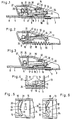
- the lock body consists of a flat base 1 and two side walls 2, which project vertically from its parallel edges and are rigidly connected to the base. It has a U-shaped cross section. Its bottom 1 contains a bore 3 for fastening an anchoring part.
- the bottom 1 and the parts of the side walls 2 adjoining it form guide devices for the insertion tongue by forming the lower and lateral delimitation of the insertion path of the insertion tongue 4, the front part 5 of which has approximately the width of the insertion path between the side walls 2. It has a locking recess 6, which forms a locking surface at 7. At its rear end, it is provided in a known manner with a recess 8 for receiving a belt loop. At the top, the insertion path is limited by projections 9 rigidly connected to the lock body.
- the known casing of the lock body by a plastic housing is not shown for the sake of simplicity. All directional information such as “top”, “right”, “clockwise” etc. refer to the representation in Fig. 1 and 2; "front” and “back” on the direction of the insertion movement.
- the lock contains an ejector plate 10 in the insertion path, which is movably guided in the direction of the insertion path in a manner not shown and is loaded against the direction of insertion by a spring 11 which is guided in bottom slots.
- a spring 11 which is guided in bottom slots.
- the locking plate consists of a rear cross part 15 connecting the projections 13 and a plate part 16 leading therefrom, which carries a locking part 17 projecting downwards at the front, which forms a locking face 18 pointing towards the rear.
- the latch part 17 protrudes slightly towards the front from the plate part 16, so that a free surface 19 is formed on its upper side, which is limited at the front by its front edge. In the locking state (FIG. 1), this area is located in the upper boundary plane of the insertion path or a little more.
- the locking plate 14 has at its rear end at least one projection 20 which is close to that through the front end of the Cutouts 12 fixed axis of rotation of the locking plate protrudes downward and limits the insertion path to the rear. Together with the ejector plate 10, it serves to positively lock the insertion tongue. This moves namely the ejector plate 10 when inserted backwards against the pressure of the ejector spring 11, the ejector plate 10 being so long that it just abuts the projection 20, thereby causing a counterclockwise rotation of the bolt when the locking surface 7 of the insertion tongue 4 has just passed under the locking face 18 of the locking portion 17.
- the locking face 18 of the locking part 17 is approximately perpendicular to the direction of the insertion path in the locked state and at an obtuse angle to the connecting line with the locking axis. If a force is exerted to the left on the latch face 18 in the direction of the insertion path, for example by a belt force acting on the insertion tongue or by the ejector spring 11, a torque is therefore exerted on the bolt which is dependent on the force acting on the insertion path and the distance of the Insertion path from the bolt axis of rotation is formed as a lever arm. This torque tries to turn the bolt clockwise, to lift the bolt part 17 out of the bolt recess of the insertion tongue and thus to release the lock. This is prevented by the pivot lever 21 in the locked state.
- This pivot lever 21 is located above the upward-facing surface 19 of the locking part 17. It is designed as a plate which extends transversely in the lock body, the outline of which can be seen in FIG. 4 on the left, while it has partially broken away on the right to provide a view of the Release the locking plate.
- the swivel lever is with its side Projections 22 are stored in cutouts 24 in the side walls 2, so that there is an axis of rotation in the region 25 (FIG. 1) which is parallel to the axis of rotation of the bolt 13-17. It can therefore be pivoted at least between the two end positions shown in FIGS. 1 and 2.
- pivot lever 21 For pivoting serves on the one hand a spring 26 which tries to pivot it counterclockwise, and on the other hand the slide 27, which is guided parallel to the insertion path in a manner not shown in the lock body and pushes against movement to the right against the upper end of the pivot lever and the pivot lever thereby rotating clockwise.
- the pivot lever 21 is held in the secured position by the spring 26 and by self-locking.
- the spring 26 is advantageously designed so that it is supported on the one hand on the lower part of the pivot lever and on the other hand on the slide 27. Both parts are thereby pushed into their normal position with double effect. It can of course be carried out differently than is shown in the drawing.
- the pivot lever is made narrower towards the center. Its upper part 40 (Fig. 4) forms a stop cooperating with the slide. To the right and left of it (Fig. 4) he leaves space for the passage of parts 41 of the slide 27, which unite behind (right of it in Fig. 1) to form an extension 30 of the slide.
- the projection 30 carries a pin 42 of certain length which projects to the rear (on the right in the illustration) and on which a screw is attached spring 43 is guided, which is longer than the pin. From the top of the bolt 14 a projection 32 protrudes near the pivot axis up to behind the pin 42 and the spring 43, the length of which is such that it does not reach the projection 32 in the locked state of the lock and thus does not exert any force on it.
- a plastic surface 34 is provided, which protrudes behind the bearing projections 13 of the bolt into the bearing cutouts 24 and therefore prevents direct, metallic contact of the bolt projections with the cutouts and prevents rattling noises.
- the ejector plate 10 In the released state of the lock (Fig. 2), the ejector plate 10 is in the insertion path under the bolt part 17 of the bolt, so that it cannot block the insertion path. It is therefore possible to move the insertion tongue 5 to the right into the insertion path, the ejector plate 10 also being pushed to the right. When the ejector plate 10 reaches the projections 20, the locking recess 6 of the insertion tongue 4 is located below the locking part 17. When the movement continues, the bolt is pivoted counterclockwise by the impact of the ejector plate 10 onto the projection 20, so that the locking part 17 is inserted into the locking recess 6 must penetrate.
- the locking surface 7 of the insertion tongue 4 exerts a force on the locking face 18 of the locking part 17 in the direction of the insertion path, the line of action of which in the insertion path and therefore at a certain distance below the pivot axis of the locking bolt 13-17 defined by the cutouts 13 runs. If the bolt were not secured in its position by the pivot lever 21, a torque would therefore be generated on the bolt 13-17 in a clockwise direction, which would force it out of the locked position into the open position.
- the geometric relationships are chosen so that this torque would normally be sufficient to open the bolt under the action of the ejector spring 11 alone.
- FIG. 5 and 6 show another embodiment of those parts of the illustrated lock which transmit the opening force from the slide extension 30 to the locking projection.
- two arms 31 are arranged which, for example, are made in one piece with the slide from an elastic plastic (for example polyamide). They end in thickened heads 45, which lie between the locking projection 32 and the rear surface 44 of the slide extension. They run across the direction of movement of the slide.
- the heads 45 When this is pushed into the lock body to open the lock (FIG. 3), the heads 45 first come into contact with the locking projection 32 and urge it to the right with further movement of the slide with resilient deformation of the arms 31, which exerts an opening force on the bolt. If the slide is moved further to the right, the state according to FIG. 6 finally occurs, in which the projection 30 exerts its force directly via the heads 45 on the locking projection without the intermediary of the resilient arms 31.
Applications Claiming Priority (2)
| Application Number | Priority Date | Filing Date | Title |
|---|---|---|---|
| DE3200770 | 1982-01-13 | ||
| DE3200770A DE3200770A1 (de) | 1982-01-13 | 1982-01-13 | Schnalle fuer einen sicherheitsgurt |
Publications (3)
| Publication Number | Publication Date |
|---|---|
| EP0083752A2 true EP0083752A2 (fr) | 1983-07-20 |
| EP0083752A3 EP0083752A3 (en) | 1985-12-04 |
| EP0083752B1 EP0083752B1 (fr) | 1988-03-23 |
Family
ID=6152956
Family Applications (1)
| Application Number | Title | Priority Date | Filing Date |
|---|---|---|---|
| EP82111564A Expired EP0083752B1 (fr) | 1982-01-13 | 1982-12-14 | Boucle pour ceintures de sécurité |
Country Status (5)
| Country | Link |
|---|---|
| US (1) | US4527317A (fr) |
| EP (1) | EP0083752B1 (fr) |
| JP (1) | JPS58124401A (fr) |
| DE (2) | DE3200770A1 (fr) |
| ES (1) | ES269633Y (fr) |
Cited By (14)
| Publication number | Priority date | Publication date | Assignee | Title |
|---|---|---|---|---|
| EP0252403A1 (fr) * | 1986-07-07 | 1988-01-13 | Van Riesen & Co. | Boucle pour système de ceinture de sécurité |
| FR2608982A1 (fr) * | 1986-12-29 | 1988-07-01 | Doebelner Beschlaege Metall | Serrure pour ceintures de securite et systemes de retenue |
| FR2621229A1 (fr) * | 1987-10-05 | 1989-04-07 | Autoflug Gmbh | Boucle de fermeture pour ceintures de securite |
| EP0364970A2 (fr) * | 1988-10-19 | 1990-04-25 | Autoliv Development Ab | Boucle pour un système de ceinture de sécurité destiné à un véhicule à moteur |
| WO1990010397A1 (fr) * | 1989-03-15 | 1990-09-20 | Autoflug Gmbh & Co. Fahrzeugtechnik | Boucle resistant aux chocs pour ceintures de securite |
| FR2657572A1 (fr) * | 1990-01-28 | 1991-08-02 | Autoflug Gmbh Cd Fahrzeugtechn | Fermeture de ceinture de securite resistant aux chocs. |
| FR2659919A1 (fr) * | 1990-03-26 | 1991-09-27 | Takata Corp | Boucle pour ceinture de securite d'un vehicule. |
| US5067211A (en) * | 1989-06-23 | 1991-11-26 | Riesen Reiner Van | Belt lock for belt strap retaining systems |
| EP0566856A1 (fr) * | 1992-04-23 | 1993-10-27 | INDIANA MILLS & MANUFACTURING, INC. | Extrémité de désaccouplement de boucle avec un linguet pivotant de dégagement |
| WO1994008480A1 (fr) * | 1992-10-09 | 1994-04-28 | Autoliv Development Ab | Boucle de ceinture de securite |
| DE4422224A1 (de) * | 1994-06-24 | 1996-01-04 | Opel Adam Ag | Sicherheitsgurtschloß |
| EP0719506A3 (fr) * | 1994-12-26 | 1996-12-18 | Takata Corp | Boucle de ceinture de sécurité |
| DE4123280C2 (de) * | 1990-07-13 | 2000-02-24 | Autoflug Gmbh | Gurtverschluß für einen Sicherheitsgurt eines Kraftfahrzeuges |
| WO2001049144A1 (fr) * | 1999-12-30 | 2001-07-12 | Delphi Technologies, Inc. | Ensemble boucle de ceinture de securite de vehicule |
Families Citing this family (26)
| Publication number | Priority date | Publication date | Assignee | Title |
|---|---|---|---|---|
| DE3331467C2 (de) * | 1983-08-31 | 1986-10-16 | TRW Repa GmbH, 7077 Alfdorf | Verschluß für einen Sicherheitsgurt |
| DE3440151A1 (de) * | 1984-11-02 | 1986-05-07 | Takata Corp., Tokio/Tokyo | Sitzgurtschliesseinrichtung |
| US4611369A (en) * | 1985-02-25 | 1986-09-16 | Trw Repa Gmbh | Belt lock for a safety belt |
| FR2584901B1 (fr) * | 1985-07-17 | 1987-11-27 | Peugeot Aciers Et Outillage | Boucle perfectionnee, notamment pour ceinture de securite |
| JPS6319103A (ja) * | 1986-07-11 | 1988-01-26 | 有限会社 睦道研究所 | 座席ベルトのバックル |
| GB2195140B (en) * | 1986-09-16 | 1990-09-26 | Autoliv Dev | Improvements in or relating to a seat belt buckle |
| JPH0540727Y2 (fr) * | 1987-03-24 | 1993-10-15 | ||
| US4802266A (en) * | 1987-05-01 | 1989-02-07 | Gateway Industries, Inc. | Seat belt buckle |
| DE3731521A1 (de) * | 1987-09-18 | 1989-03-30 | Bsrd Ltd | Gurtschloss fuer einen sicherheitsgurt eines fahrzeugs, insbesondere kraftfahrzeugs |
| GB2214970B (en) * | 1988-02-10 | 1992-06-10 | Gen Engineering | Improvements in or relating to a safety-belt buckle |
| US4876772A (en) * | 1988-02-25 | 1989-10-31 | Indiana Mills & Manufacturing, Inc. | Safety belt buckle |
| US4942649A (en) * | 1988-02-25 | 1990-07-24 | Indiana Mills & Manufacturing, Inc. | Safety belt buckle |
| GB2218457B (en) * | 1988-05-11 | 1992-03-18 | Gen Motors Corp | Seat belt buckle. |
| DE4015235C1 (en) * | 1990-05-13 | 1991-11-21 | Autoflug Gmbh & Co Fahrzeugtechnik, 2084 Rellingen, De | Safety belt lock - has built-in sprung ejector and bolt to engage slot in tongue and hold until release by slide in housing |
| JP2530975Y2 (ja) * | 1991-02-01 | 1997-04-02 | 日本精工株式会社 | シートベルト用バックル |
| US5267377A (en) * | 1992-09-01 | 1993-12-07 | Trw Vehicle Safety Systems Inc. | Buckle assembly |
| DE9414029U1 (de) * | 1994-08-30 | 1994-10-20 | Trw Repa Gmbh | Verschluß für Sicherheitsgurte |
| ES1029944Y (es) * | 1995-01-20 | 1996-01-01 | Perlas Manacor Sa | Cierre para collares de disposicion frontal. |
| US5568676A (en) * | 1995-03-08 | 1996-10-29 | Indiana Mills And Manufacturing, Inc. | End release buckle |
| JP3650271B2 (ja) | 1998-07-27 | 2005-05-18 | 株式会社東海理化電機製作所 | バックル |
| US6055708A (en) * | 1999-08-10 | 2000-05-02 | Trw Vehicle Safety Systems Inc. | Seat belt buckle with a shield blocking a tongue receiving opening |
| JP3432471B2 (ja) * | 1999-12-08 | 2003-08-04 | カツヤマファインテック株式会社 | シートベルト用バックル |
| CN1325002C (zh) * | 2001-06-08 | 2007-07-11 | 株式会社东海理化电机制作所 | 座椅安全带扣 |
| CN104544773B (zh) * | 2013-10-29 | 2018-02-09 | 比亚迪股份有限公司 | 带扣装置 |
| CN112237315B (zh) * | 2019-07-17 | 2023-09-29 | 明门瑞士股份有限公司 | 扣具 |
| CN117016924A (zh) | 2019-07-17 | 2023-11-10 | 明门瑞士股份有限公司 | 扣具 |
Citations (4)
| Publication number | Priority date | Publication date | Assignee | Title |
|---|---|---|---|---|
| DE2835118B1 (de) * | 1978-08-10 | 1979-08-30 | Kolb Gmbh & Co Hans | Verschlussschnalle fuer Sicherheitsgurte,insbesondere Kraftfahrzeug-Sicherheitsgurte |
| DE2828082A1 (de) * | 1978-06-27 | 1980-01-10 | Stahl Gurt Bandweberei | Gurtschloss, insbesondere fuer sicherheitsgurte |
| DE2933018A1 (de) * | 1961-10-04 | 1980-03-06 | Kangol Magnet Ltd | Gurtschnalle fuer kraftfahrzeug- sicherheitsgurte |
| GB2039590A (en) * | 1979-01-17 | 1980-08-13 | Kangol Magnet Ltd | Buckle for a safety belt system |
Family Cites Families (13)
| Publication number | Priority date | Publication date | Assignee | Title |
|---|---|---|---|---|
| DE52160C (de) * | W. KRÜGER in Berlin N., Franseckistrafse 2 | Deichselbefestigung für Wagen aller Art | ||
| US3562877A (en) * | 1968-10-07 | 1971-02-16 | Robbins Seat Belt Co | Miniature buckle |
| US4096606A (en) * | 1976-03-04 | 1978-06-27 | Allied Chemical Corporation | Ferrule buckle with sliding release button |
| GB1572106A (en) * | 1976-12-13 | 1980-07-23 | Wall Ltd Howard | Anchoring devices |
| JPS577284Y2 (fr) * | 1977-10-21 | 1982-02-12 | ||
| DE2844977A1 (de) * | 1978-10-16 | 1980-04-24 | Klippan Nv | Verriegelungsschloss mit leicht loesbarem verschlusstueck |
| SE7812170L (sv) * | 1977-12-07 | 1979-06-08 | Klippan Nv | Belteslas med lett frigorbar sperr |
| SE435893B (sv) * | 1978-08-15 | 1984-10-29 | Autoliv Ab | Spenne for fordonssekerhetssele |
| DE2903230A1 (de) * | 1979-01-29 | 1980-07-31 | Holger Seel | Sicherheitsgurtverschluss |
| FR2482430B1 (fr) * | 1980-05-14 | 1983-12-23 | Peugeot Aciers Et Outillage | |
| DE3021796C2 (de) * | 1980-06-11 | 1985-03-28 | Repa Feinstanzwerk Gmbh, 7071 Alfdorf | Sicherheitsgurtverschluß |
| ATE8566T1 (de) * | 1980-11-18 | 1984-08-15 | Autoflug Gmbh | Schnalle fuer einen sicherheitsgurt. |
| US4358879A (en) * | 1980-12-01 | 1982-11-16 | General Motors Corporation | Seat belt buckle |
-
1982
- 1982-01-13 DE DE3200770A patent/DE3200770A1/de not_active Withdrawn
- 1982-12-14 DE DE8282111564T patent/DE3278262D1/de not_active Expired
- 1982-12-14 EP EP82111564A patent/EP0083752B1/fr not_active Expired
-
1983
- 1983-01-07 US US06/456,587 patent/US4527317A/en not_active Expired - Fee Related
- 1983-01-10 ES ES1983269633U patent/ES269633Y/es not_active Expired
- 1983-01-13 JP JP58005145A patent/JPS58124401A/ja active Granted
Patent Citations (4)
| Publication number | Priority date | Publication date | Assignee | Title |
|---|---|---|---|---|
| DE2933018A1 (de) * | 1961-10-04 | 1980-03-06 | Kangol Magnet Ltd | Gurtschnalle fuer kraftfahrzeug- sicherheitsgurte |
| DE2828082A1 (de) * | 1978-06-27 | 1980-01-10 | Stahl Gurt Bandweberei | Gurtschloss, insbesondere fuer sicherheitsgurte |
| DE2835118B1 (de) * | 1978-08-10 | 1979-08-30 | Kolb Gmbh & Co Hans | Verschlussschnalle fuer Sicherheitsgurte,insbesondere Kraftfahrzeug-Sicherheitsgurte |
| GB2039590A (en) * | 1979-01-17 | 1980-08-13 | Kangol Magnet Ltd | Buckle for a safety belt system |
Cited By (21)
| Publication number | Priority date | Publication date | Assignee | Title |
|---|---|---|---|---|
| EP0252403A1 (fr) * | 1986-07-07 | 1988-01-13 | Van Riesen & Co. | Boucle pour système de ceinture de sécurité |
| FR2608982A1 (fr) * | 1986-12-29 | 1988-07-01 | Doebelner Beschlaege Metall | Serrure pour ceintures de securite et systemes de retenue |
| FR2621229A1 (fr) * | 1987-10-05 | 1989-04-07 | Autoflug Gmbh | Boucle de fermeture pour ceintures de securite |
| EP0364970A3 (fr) * | 1988-10-19 | 1991-07-03 | Autoliv Development Ab | Boucle pour un système de ceinture de sécurité destiné à un véhicule à moteur |
| EP0364970A2 (fr) * | 1988-10-19 | 1990-04-25 | Autoliv Development Ab | Boucle pour un système de ceinture de sécurité destiné à un véhicule à moteur |
| GB2249806A (en) * | 1989-03-15 | 1992-05-20 | Autoflug Gmbh | Shockproof buckle for safety belts |
| WO1990010397A1 (fr) * | 1989-03-15 | 1990-09-20 | Autoflug Gmbh & Co. Fahrzeugtechnik | Boucle resistant aux chocs pour ceintures de securite |
| GB2249806B (en) * | 1989-03-15 | 1993-07-07 | Autoflug Gmbh | Shock protected buckle for safety belts |
| FR2644329A1 (fr) * | 1989-03-15 | 1990-09-21 | Autoflug Gmbh | |
| US5067211A (en) * | 1989-06-23 | 1991-11-26 | Riesen Reiner Van | Belt lock for belt strap retaining systems |
| FR2657572A1 (fr) * | 1990-01-28 | 1991-08-02 | Autoflug Gmbh Cd Fahrzeugtechn | Fermeture de ceinture de securite resistant aux chocs. |
| FR2659919A1 (fr) * | 1990-03-26 | 1991-09-27 | Takata Corp | Boucle pour ceinture de securite d'un vehicule. |
| DE4123280C2 (de) * | 1990-07-13 | 2000-02-24 | Autoflug Gmbh | Gurtverschluß für einen Sicherheitsgurt eines Kraftfahrzeuges |
| EP0566856A1 (fr) * | 1992-04-23 | 1993-10-27 | INDIANA MILLS & MANUFACTURING, INC. | Extrémité de désaccouplement de boucle avec un linguet pivotant de dégagement |
| US5555609A (en) * | 1992-10-09 | 1996-09-17 | Autoliv Development Ab | Safety belt buckle |
| WO1994008480A1 (fr) * | 1992-10-09 | 1994-04-28 | Autoliv Development Ab | Boucle de ceinture de securite |
| DE4422224A1 (de) * | 1994-06-24 | 1996-01-04 | Opel Adam Ag | Sicherheitsgurtschloß |
| DE4422224C2 (de) * | 1994-06-24 | 2003-06-26 | Opel Adam Ag | Sicherheitsgurtschloß |
| EP0719506A3 (fr) * | 1994-12-26 | 1996-12-18 | Takata Corp | Boucle de ceinture de sécurité |
| WO2001049144A1 (fr) * | 1999-12-30 | 2001-07-12 | Delphi Technologies, Inc. | Ensemble boucle de ceinture de securite de vehicule |
| US6438810B2 (en) | 1999-12-30 | 2002-08-27 | Delphi Technologies, Inc. | Seat restraint buckle assembly |
Also Published As
| Publication number | Publication date |
|---|---|
| ES269633U (es) | 1983-07-01 |
| JPS58124401A (ja) | 1983-07-25 |
| JPH0376923B2 (fr) | 1991-12-09 |
| US4527317A (en) | 1985-07-09 |
| DE3200770A1 (de) | 1983-07-21 |
| ES269633Y (es) | 1984-01-16 |
| EP0083752A3 (en) | 1985-12-04 |
| DE3278262D1 (en) | 1988-04-28 |
| EP0083752B1 (fr) | 1988-03-23 |
Similar Documents
| Publication | Publication Date | Title |
|---|---|---|
| EP0083752B1 (fr) | Boucle pour ceintures de sécurité | |
| DE10325099A1 (de) | Seitenverriegelungsvorrichtung | |
| EP0212507A2 (fr) | Boucle de verrouillage pour ceinture de sécurité | |
| DE19649209A1 (de) | Außenseitige Türgriffbaugruppe für Kraftfahrzeuge | |
| DE2345593C3 (de) | Kupplungsvorrichtung | |
| DE3537465C2 (fr) | ||
| DE3213342A1 (de) | Schloss fuer sicherheitsgurte | |
| EP0204944B1 (fr) | Serrure de secours avec pêne, en particulier pour portes avec châssis tubulaire | |
| DE3927877C2 (fr) | ||
| EP1669526A2 (fr) | Serrure de véhicule automobile | |
| DE2903230A1 (de) | Sicherheitsgurtverschluss | |
| DE3308362C2 (de) | Verschluß für Sicherheitsgurte o.dgl. | |
| EP0133193A2 (fr) | Serrure à combinaisons pour valise ou similaire | |
| DE3006151C2 (fr) | ||
| DE2043780B2 (de) | Innenverriegelungseinrichtung für einen Kraftfahrzeug-Türverschluß | |
| DE1905074C2 (de) | Verschlußvorrichtung | |
| DE3342783C2 (de) | Sicherheitsgurtverschluss mit drehbarer Sperrklinke | |
| DE3324850C2 (fr) | ||
| DE3717096C2 (de) | Schnappschloß mit Betätigungsvorrichtung als Muschelgriff | |
| DE2811861C3 (de) | Feststeller für den schwenkbaren Flügel einer Fahrzeugtür | |
| EP0167767A2 (fr) | Dispositif de verrouillage comportant au moins un verrou et des moyens de condamnation | |
| DE4109947C2 (de) | Verschluß für Sicherheitsgurte | |
| DE3440151C2 (fr) | ||
| DE2649559C2 (de) | Verschluß für Sicherheitsgurte | |
| DE2342574A1 (de) | Drehfallen-schloss fuer eine schiebetuer |
Legal Events
| Date | Code | Title | Description |
|---|---|---|---|
| PUAI | Public reference made under article 153(3) epc to a published international application that has entered the european phase |
Free format text: ORIGINAL CODE: 0009012 |
|
| AK | Designated contracting states |
Designated state(s): DE FR GB IT SE |
|
| PUAL | Search report despatched |
Free format text: ORIGINAL CODE: 0009013 |
|
| AK | Designated contracting states |
Designated state(s): DE FR GB IT SE |
|
| 17P | Request for examination filed |
Effective date: 19860303 |
|
| 17Q | First examination report despatched |
Effective date: 19870529 |
|
| GRAA | (expected) grant |
Free format text: ORIGINAL CODE: 0009210 |
|
| AK | Designated contracting states |
Kind code of ref document: B1 Designated state(s): DE FR GB IT SE |
|
| PG25 | Lapsed in a contracting state [announced via postgrant information from national office to epo] |
Ref country code: SE Effective date: 19880331 |
|
| REF | Corresponds to: |
Ref document number: 3278262 Country of ref document: DE Date of ref document: 19880428 |
|
| ITF | It: translation for a ep patent filed |
Owner name: UFFICIO TECNICO ING. A. MANNUCCI |
|
| GBT | Gb: translation of ep patent filed (gb section 77(6)(a)/1977) | ||
| ET | Fr: translation filed | ||
| PLBE | No opposition filed within time limit |
Free format text: ORIGINAL CODE: 0009261 |
|
| STAA | Information on the status of an ep patent application or granted ep patent |
Free format text: STATUS: NO OPPOSITION FILED WITHIN TIME LIMIT |
|
| 26N | No opposition filed | ||
| PGFP | Annual fee paid to national office [announced via postgrant information from national office to epo] |
Ref country code: SE Payment date: 19901219 Year of fee payment: 9 |
|
| ITTA | It: last paid annual fee | ||
| PGFP | Annual fee paid to national office [announced via postgrant information from national office to epo] |
Ref country code: GB Payment date: 19941209 Year of fee payment: 13 |
|
| PGFP | Annual fee paid to national office [announced via postgrant information from national office to epo] |
Ref country code: FR Payment date: 19941215 Year of fee payment: 13 |
|
| PG25 | Lapsed in a contracting state [announced via postgrant information from national office to epo] |
Ref country code: GB Effective date: 19951214 |
|
| GBPC | Gb: european patent ceased through non-payment of renewal fee |
Effective date: 19951214 |
|
| PG25 | Lapsed in a contracting state [announced via postgrant information from national office to epo] |
Ref country code: FR Effective date: 19960830 |
|
| REG | Reference to a national code |
Ref country code: FR Ref legal event code: ST |
|
| PGFP | Annual fee paid to national office [announced via postgrant information from national office to epo] |
Ref country code: DE Payment date: 20020109 Year of fee payment: 20 |