EP0079068B1 - Anhänger für Kraftfahrzeuge - Google Patents
Anhänger für Kraftfahrzeuge Download PDFInfo
- Publication number
- EP0079068B1 EP0079068B1 EP82110261A EP82110261A EP0079068B1 EP 0079068 B1 EP0079068 B1 EP 0079068B1 EP 82110261 A EP82110261 A EP 82110261A EP 82110261 A EP82110261 A EP 82110261A EP 0079068 B1 EP0079068 B1 EP 0079068B1
- Authority
- EP
- European Patent Office
- Prior art keywords
- board
- frame
- section
- trailer according
- wing
- Prior art date
- Legal status (The legal status is an assumption and is not a legal conclusion. Google has not performed a legal analysis and makes no representation as to the accuracy of the status listed.)
- Expired
Links
Images


Classifications
-
- B—PERFORMING OPERATIONS; TRANSPORTING
- B62—LAND VEHICLES FOR TRAVELLING OTHERWISE THAN ON RAILS
- B62D—MOTOR VEHICLES; TRAILERS
- B62D63/00—Motor vehicles or trailers not otherwise provided for
- B62D63/06—Trailers
-
- B—PERFORMING OPERATIONS; TRANSPORTING
- B62—LAND VEHICLES FOR TRAVELLING OTHERWISE THAN ON RAILS
- B62D—MOTOR VEHICLES; TRAILERS
- B62D63/00—Motor vehicles or trailers not otherwise provided for
- B62D63/06—Trailers
- B62D63/062—Trailers with one axle or two wheels
- B62D63/064—Trailers with one axle or two wheels light luggage or equipment trailers, e.g. for batteries, gas generators, gas bottles, stretchers
Definitions
- a trailer of this type is e.g. B. from the patent DE-C-802 212 known.
- a profile rod or frame in particular for plastic sheets or the like, with a flat central web and two legs running at right angles to it, at least one of which is cranked or bent toward the other leg in such a way that the distance between the parallel legs Leg parts corresponds to the thickness of the plate to be fastened between them (DE-U-7 126 992).
- This known profile bar or frame forms an edge protection for the plastic plates mentioned. It is made of light metal.
- the profiles or frames are reinforced in particular at the corners by specially inserted inserts, on the one hand to achieve a durable corner connection on the one hand, but on the other hand to give the frame itself the strength that the profile must have in rough operation, particularly at the corners, to withstand high loads, especially when used in a trailer body.
- the profiles are separated in the corner connections with a miter cut.
- the usual corner connection is made by special corner connectors, preferably made of steel, which are inserted into correspondingly prepared guides within the light metal profile bars.
- the invention has set itself the task of avoiding the disadvantages and other disadvantages of known trailer structures and to create a trailer for motor vehicles, the individual parts can also be standardized to a certain extent, which are therefore interchangeable and also allow different types of structures some of the same individual elements.
- a trailer of the generic type is characterized in that the central part of the profile projects beyond the edge of the plate on one side by an amount which corresponds to at least approximately half the plate thickness and is angled towards the plate and ends in the other leg, whereby at least the middle part of the profile of the frame is angled without interruption in the frame corners and that the attachment of the frame to the plate is carried out by means of transversely carried out screws and to produce a right-angled connection of two side walls either the cross-section through the plate of a first side wall and profile legs lying thereon guided screw is screwed through a through hole arranged in the profile in the region of the end edge of the plate of a second side wall into a welding nut arranged in the interior of the profile or, when the screw head is inserted into the profile on the plate of the second side wall, the screw shaft is durc h the through hole arranged in profile in the region of the end edge of the second plate and then in the region of the adjacent legs through the plate of the first side wall and provided outside of this plate with
- the above-described type of design of the profiles ensures that these profiles have a substantially higher strength and that the plates surrounded by the profiles can therefore be significantly thinner because they are considerably relieved of forces.
- Such thinner plates can also advantageously be designed in such a way that they are significantly more resistant to other influences, such as, for example, moisture, wetness, temperatures and the like.
- the formation of the frame profiles gives the further advantage that the surfaces of the panels are much better protected against mechanical influences, particularly in traffic, by the frame edges projecting outwards, and that these frame edges can also be used to produce special connections.
- the metal profile frame has miter cutouts on its legs, corresponding to the corners of the panel to be framed, and angled. This is a material Connection of all frame parts achieved and a correspondingly better power flow transmission.
- the frame profile is preferably finished on a long side of the plate at a distance from the corners and a straight profile piece is inserted between these ends.
- the ends of the plate surrounding the angled frame portion may be located at the site of the plate where it by half of a screwed or - are covered riveted fitting, with the other half of the fitting covers the ends of the straight profile piece used.
- the frame can consist of two parts, the ends of which abut each other on two opposite side edges of the plate.
- the frame can also consist of one part and abut one another with its two ends in the course of a side edge of the plate.
- the frame consists of a few or a part, so that not only the manufacture is much easier and cheaper, but also that the flow of force within the individual pieces of the frame is ensured.
- the outer edges of the two mutually parallel legs are advantageously bent inwards relative to one another. This also prevents accidents.
- the connection between the frame profile and the plate is improved.
- the trailer platform which is essentially designed as a U-profile encompassing the platform at its edges, with the upper leg in the width of approximately the frame profile of the upstanding side edges and angled upwards behind it , and reaching up to the height of the wall frame profile, while the lower leg projects beyond the contact surface of the upper one on the platform.
- the upwardly angled leg is connected to the side wall by means of screws or rivets which penetrate this leg and the two legs of the side wall frame and the plate in between.
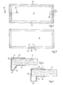
- a vehicle trailer according to the invention consists of the chassis with the wheels 1 and a platform or base plate 2, the side walls 3 and the front wall 4 and the rear wall 5.
- the individual walls are made of wood, wood material or other material, and they are surrounded by metal profiles on all sides.
- the metal frames surrounding the plate 6 have two mutually parallel legs, namely an inner leg 7 and an outer leg 8. From the inner leg 7, the frame profile is bent around the edge 9 of the wall plate or angled and forms a central part 10 which projects over this edge 9 of the plate 6 on one side. Middle part 10 and leg 7 preferably have the same length. That part of the middle part 10 which projects beyond the thickness of the plate 6 is at least approximately as long as half the plate thickness 6. According to the exemplary embodiment in FIG. 4, an oblique connection 12 to the leg 8 of the profile can be made from the outer end of the middle part 10 with a double bend 11. An obtuse angle is then present between the leg 8 and the inclined part 12, while an acute angle is present between the middle part 10 and the inclined part 12.
- a right-angled bend 13 is first made from the central part at the end of the projecting part, and from this a further right-angled bend 14 leads to the leg 8 of the frame profile.
- the frame which surrounds a side wall 3, 4 or 5 consists of two parts 15 and 16, which are mirror-symmetrical and are pushed over the plate from above and below. Holes 17 are arranged for connection, two of which lie in the two mutually abutting ends 18 of the frame parts. Another of the holes 17 can also be in the plate 6. These holes, which serve to connect the two frame parts, are used at the same time for attaching fittings, in the present case for example for attaching a closing fitting, in the event that a rear wall 5 is involved.
- the entire frame surrounding the plate 6 is formed in one piece, miters are cut at the corners, so that the parts of the profiles forming the outer frame edges must be angled.
- an embodiment not shown here is applicable to a side wall 3.
- the surrounding profile frame for the side wall 3 is designed such that it surrounds all side edges, similar to FIG. 3, but at the lower side edge there is a greater distance between the joints 19.
- a separate profile frame part is used, and at the double joints in this case there are attachment points for fasteners of the mudguard 26 which surrounds the upper part of the wheel 1.
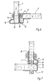
- FIG. 6 shows the corner connection of two side walls.
- the side wall 3 is connected to the front wall 4.
- the central part 10 of the frame profile of the side wall 3 is placed against the leg 7 of the frame profile of the end wall 4 of approximately the same length.
- the two parts lying one on top of the other are provided with a through hole.
- the plate 6 of the end wall 4 is provided with a through hole and likewise the leg 8 on the outside of the end wall.
- a screw with its head can be inserted in a recess in the plate 6, which is assigned to the frame perforation, in such a way that its shaft protrudes from the frame of the side wall.
- the shaft of this screw is passed through the through holes in the end wall, and a nut is screwed onto the outside.
- a welding nut can also be placed on the hole in the middle part 10 of the frame within the middle part 10 of the frame of the side wall, so that a screw can be screwed into this welding nut from the outside through the prepared perforation in the end wall 4.
- one part of this screw connection is invisible and protected against damage.
- the exposed part of the connection is surmounted by the projecting part of the frame of the end wall 4. This projecting part consists of the extension of the middle part 10 and the angled parts 13 and 14.
- a welding nut is used within the frame of the side wall 3, this can also be arranged in accordance with FIGS. 8 and 9.
- the central part 10 of the frame on the profile wall is offset inward by approximately the thickness of this wall, so that, for example, there is still space between the two frame parts lying on top of one another for the attachment of an intermediate washer, which can be made of an elastic material.
- the welding nut 29 is preferably arranged in the region of the edge 9 of the plate 6 used, and for this purpose the plate is provided with a recess at this point.
- the welding nut 29 can, however, also be placed in the area of the “bulge” of the frame profile from the inside onto the elongated central part 10 opposite the profile part 14, which means that the side wall 3 in the connection has moved further inwards and the “bulge” the profile of the frame of the side wall 3 is aligned with the hole in the two legs 7 and 8 of the profile of the frame of the end wall 4.
- the “bulge” also extends beyond the fastening means or their heads for the frame on a side wall itself.
- These fastenings are generally carried out with rivets, in which the heads are flat, lenticular, so that there are no significant projections beyond the plane of the side wall outwards or inwards.
- screws can also be used for fastening the frame to the plate, which lie on the long legs 8 with flat lens heads, while they are secured on the opposite side, the short leg 8, for example with head nuts.
- the formation of the floor platform and the connection of the walls to the platform is carried out in the following manner: In the lower leg 22, a middle part 23 covering the edge of the floor plate or platform is produced by an angling, from which in turn the upper leg 24 is angled inwards. This is followed by an upstanding bend 25, the length of which corresponds approximately to the length of the long flange 7 of the frame profiles of the side walls. It can be seen from FIG. 7 how the connection is established.
- the length of the upper leg 24 corresponds approximately to the middle piece 10 of the side wall profiles, so that when the side walls are inserted, the middle part 10 and the long flange 7 parallel to the leg 24 of the floor profile and the upstanding part 25 of the floor profile, the latter being provided on its upper edge with an outward angled portion which overlaps the corresponding angled portion on the long leg of the profile of the frame of the side walls.
- the connection is made by means of screws or welding nuts 29, as has already been described in connection with the connection of the side walls to one another with reference to FIG. 6.
- connection can be made above this corner connection by passing a screw through the parallel legs of the side wall profiles and the upstanding part 25 of the floor profile. A particularly good securing of this corner connection is thus achieved.
- the upper connection can also be used, for example, to attach the side fenders 26.
Landscapes
- Engineering & Computer Science (AREA)
- Chemical & Material Sciences (AREA)
- Combustion & Propulsion (AREA)
- Transportation (AREA)
- Mechanical Engineering (AREA)
- Body Structure For Vehicles (AREA)
- Connection Of Plates (AREA)
Applications Claiming Priority (2)
| Application Number | Priority Date | Filing Date | Title |
|---|---|---|---|
| DE19818132786 DE8132786U1 (de) | 1981-11-10 | 1981-11-10 | Anhaenger fuer kraftfahrzeuge |
| DE8132786U | 1981-11-10 |
Publications (3)
| Publication Number | Publication Date |
|---|---|
| EP0079068A2 EP0079068A2 (de) | 1983-05-18 |
| EP0079068A3 EP0079068A3 (en) | 1983-09-07 |
| EP0079068B1 true EP0079068B1 (de) | 1986-10-29 |
Family
ID=6732866
Family Applications (2)
| Application Number | Title | Priority Date | Filing Date |
|---|---|---|---|
| EP82110261A Expired EP0079068B1 (de) | 1981-11-10 | 1982-11-06 | Anhänger für Kraftfahrzeuge |
| EP82110260A Expired EP0087504B1 (de) | 1981-11-10 | 1982-11-06 | Anhänger für Kraftfahrzeuge |
Family Applications After (1)
| Application Number | Title | Priority Date | Filing Date |
|---|---|---|---|
| EP82110260A Expired EP0087504B1 (de) | 1981-11-10 | 1982-11-06 | Anhänger für Kraftfahrzeuge |
Country Status (3)
| Country | Link |
|---|---|
| EP (2) | EP0079068B1 (da) |
| DE (1) | DE8132786U1 (da) |
| DK (2) | DK155719C (da) |
Families Citing this family (8)
| Publication number | Priority date | Publication date | Assignee | Title |
|---|---|---|---|---|
| DE3667949D1 (de) * | 1986-03-04 | 1990-02-08 | Heinemann W Gmbh & Co Kg | Anhaenger fuer personenkraftwagen. |
| SE458110B (sv) * | 1987-06-26 | 1989-02-27 | Gisebo Vagnindustri Ab | Hoernstolpe foer slaepkaerra |
| KR100364251B1 (ko) * | 2000-04-15 | 2002-12-11 | 옵티시스 주식회사 | 유니버셜 시리얼 버스 커넥팅장치 |
| FR2807991B1 (fr) * | 2000-04-21 | 2002-07-19 | Amca Noval | Remorque routiere modulaire |
| US6669271B2 (en) | 2001-06-22 | 2003-12-30 | East Manufacturing Corporation | Smooth side body structure and method |
| US7152909B2 (en) | 2001-06-22 | 2006-12-26 | East Manufacturing Corporation | Trailer and trailer body construction and extruded panel for same |
| CA2517419A1 (en) * | 2005-08-26 | 2007-02-26 | Jade Specialty Products Inc. | Trailer with removable wheels |
| DE202018001409U1 (de) | 2018-03-16 | 2019-06-18 | Jansen Ag | Rahmenprofil |
Family Cites Families (3)
| Publication number | Priority date | Publication date | Assignee | Title |
|---|---|---|---|---|
| DE7126992U (de) * | 1971-10-28 | Brandt W | Profilstab oder -rahmen, insbesondere für Kunststoffplatten und dgl | |
| DE802212C (de) * | 1949-01-14 | 1951-02-05 | Ernst Hahn | Verfahren zur Herstellung eines Anhaenger-Kastenaufbaus und Kastenaufbau, insbesondere fuer Anhaenger von Personenkraftwagen |
| DE8211026U1 (de) * | 1982-04-19 | 1982-08-12 | Schultheis, Wilhelm, 6050 Offenbach | Automatische hub- und schwenkvorrichtung fuer faesser o. dgl. |
-
1981
- 1981-11-10 DE DE19818132786 patent/DE8132786U1/de not_active Expired
-
1982
- 1982-11-06 EP EP82110261A patent/EP0079068B1/de not_active Expired
- 1982-11-06 EP EP82110260A patent/EP0087504B1/de not_active Expired
- 1982-11-09 DK DK498282A patent/DK155719C/da not_active IP Right Cessation
- 1982-11-09 DK DK498182A patent/DK155426C/da not_active IP Right Cessation
Non-Patent Citations (1)
| Title |
|---|
| Metallbearbeitung, Band II, Seiten 34, 35, 1970 Gie~en * |
Also Published As
| Publication number | Publication date |
|---|---|
| DK155719C (da) | 1989-09-25 |
| EP0087504A1 (de) | 1983-09-07 |
| DE8132786U1 (de) | 1982-04-22 |
| EP0079068A3 (en) | 1983-09-07 |
| DK498182A (da) | 1983-05-11 |
| DK155426C (da) | 1989-08-21 |
| DK155426B (da) | 1989-04-10 |
| DK155719B (da) | 1989-05-08 |
| DK498282A (da) | 1983-05-11 |
| EP0079068A2 (de) | 1983-05-18 |
| EP0087504B1 (de) | 1988-10-12 |
Similar Documents
| Publication | Publication Date | Title |
|---|---|---|
| DE19638156B4 (de) | Aufbau für oberen Karosserieabschnitt einer Fahrzeugkarosserie | |
| DE2829671A1 (de) | Eckverbindung fuer die einen ueberrollschutz an fahrzeugen bildenden, in einer ecke zusammenstossenden traeger, streben, stuetzen o.dgl. | |
| DE102005038150B4 (de) | Schlussquerträger für ein Nutzfahrzeug | |
| EP0186625B1 (de) | Fahrzeug-Chassis | |
| DE19545069A1 (de) | Stoßstange mit Querträger in Halbschalenbauweise | |
| EP0267152B1 (de) | Bauprofilsatz für das Kastengerippe eines Nutzfahrzeuges sowie Gerippe | |
| DE29800368U1 (de) | Geschraubter Hilfsrahmen | |
| WO2020038972A1 (de) | Batteriegehäuse für ein elektromotorisch angetriebenes fahrzeug | |
| EP0079068B1 (de) | Anhänger für Kraftfahrzeuge | |
| DE9304926U1 (de) | Fahrgestell für Fahrzeuganhänger | |
| DE3706315C3 (de) | Schrank | |
| EP2524855B1 (de) | Aufbau für ein Nutzfahrzeug | |
| DE9418262U1 (de) | Profilanordnung und ihre Verwendung zur Herstellung von Rahmenprofilen für Aufbauten | |
| DE3606812A1 (de) | Verkleidung fuer einen einstiegsschweller eines kraftfahrzeugs | |
| DE3927082A1 (de) | Automobilstossfaenger | |
| EP2116460B1 (de) | Kofferaufbau mit einem zwei Verbindungshälften aufweisenden Verbindungselement | |
| EP0065623A1 (de) | Flanschkonstruktion für die Schraubverbindung zwischen einem Anhänger-Fahrgestell und dem Rahmen des Anhänger-Aufbaues | |
| DE19818265A1 (de) | Fahrzeugtür | |
| DE3301324A1 (de) | Verbesserungen bei rahmenteilen fuer fenster, tueren und anderen rahmenkonstruktionen | |
| DE19843400A1 (de) | Bodengruppe für einen Fahrzeuganhänger, vorzugsweiseeinen Wohnanhänger | |
| DE4036413C2 (de) | Quertraverse für Container und Wechselaufbauten | |
| DE2248575A1 (de) | Vorrichtung zum verbinden und befestigen von blechen oder platten | |
| DE3247078A1 (de) | Runge fuer lastkraftwagen und anhaenger | |
| DE8715774U1 (de) | Schrank | |
| DE8219290U1 (de) | Ein- oder tandemachsiger Kraftfahrzeuganhänger |
Legal Events
| Date | Code | Title | Description |
|---|---|---|---|
| PUAI | Public reference made under article 153(3) epc to a published international application that has entered the european phase |
Free format text: ORIGINAL CODE: 0009012 |
|
| AK | Designated contracting states |
Designated state(s): BE FR NL |
|
| PUAL | Search report despatched |
Free format text: ORIGINAL CODE: 0009013 |
|
| AK | Designated contracting states |
Designated state(s): BE FR NL |
|
| 17P | Request for examination filed |
Effective date: 19831014 |
|
| GRAA | (expected) grant |
Free format text: ORIGINAL CODE: 0009210 |
|
| AK | Designated contracting states |
Kind code of ref document: B1 Designated state(s): BE FR NL |
|
| ET | Fr: translation filed | ||
| PLBE | No opposition filed within time limit |
Free format text: ORIGINAL CODE: 0009261 |
|
| STAA | Information on the status of an ep patent application or granted ep patent |
Free format text: STATUS: NO OPPOSITION FILED WITHIN TIME LIMIT |
|
| 26N | No opposition filed | ||
| PGFP | Annual fee paid to national office [announced via postgrant information from national office to epo] |
Ref country code: FR Payment date: 19931115 Year of fee payment: 12 |
|
| PGFP | Annual fee paid to national office [announced via postgrant information from national office to epo] |
Ref country code: BE Payment date: 19931208 Year of fee payment: 12 |
|
| PG25 | Lapsed in a contracting state [announced via postgrant information from national office to epo] |
Ref country code: BE Effective date: 19941130 |
|
| PGFP | Annual fee paid to national office [announced via postgrant information from national office to epo] |
Ref country code: NL Payment date: 19941130 Year of fee payment: 13 |
|
| BERE | Be: lapsed |
Owner name: WESTFALIA-WERKE FRANZ KNOBEL & SOHNE K.G. Effective date: 19941130 |
|
| PG25 | Lapsed in a contracting state [announced via postgrant information from national office to epo] |
Ref country code: FR Effective date: 19950731 |
|
| REG | Reference to a national code |
Ref country code: FR Ref legal event code: ST |
|
| PG25 | Lapsed in a contracting state [announced via postgrant information from national office to epo] |
Ref country code: NL Effective date: 19960601 |
|
| NLV4 | Nl: lapsed or anulled due to non-payment of the annual fee |
Effective date: 19960601 |