EP0076868B1 - Procédé de gravure par rayons à électrons et dispositif pour sa réalisation - Google Patents
Procédé de gravure par rayons à électrons et dispositif pour sa réalisation Download PDFInfo
- Publication number
- EP0076868B1 EP0076868B1 EP81108156A EP81108156A EP0076868B1 EP 0076868 B1 EP0076868 B1 EP 0076868B1 EP 81108156 A EP81108156 A EP 81108156A EP 81108156 A EP81108156 A EP 81108156A EP 0076868 B1 EP0076868 B1 EP 0076868B1
- Authority
- EP
- European Patent Office
- Prior art keywords
- lens
- electron beam
- pinholes
- focal length
- screen
- Prior art date
- Legal status (The legal status is an assumption and is not a legal conclusion. Google has not performed a legal analysis and makes no representation as to the accuracy of the status listed.)
- Expired
Links
Images

Classifications
-
- B—PERFORMING OPERATIONS; TRANSPORTING
- B41—PRINTING; LINING MACHINES; TYPEWRITERS; STAMPS
- B41C—PROCESSES FOR THE MANUFACTURE OR REPRODUCTION OF PRINTING SURFACES
- B41C1/00—Forme preparation
- B41C1/02—Engraving; Heads therefor
- B41C1/04—Engraving; Heads therefor using heads controlled by an electric information signal
- B41C1/05—Heat-generating engraving heads, e.g. laser beam, electron beam
-
- B—PERFORMING OPERATIONS; TRANSPORTING
- B23—MACHINE TOOLS; METAL-WORKING NOT OTHERWISE PROVIDED FOR
- B23K—SOLDERING OR UNSOLDERING; WELDING; CLADDING OR PLATING BY SOLDERING OR WELDING; CUTTING BY APPLYING HEAT LOCALLY, e.g. FLAME CUTTING; WORKING BY LASER BEAM
- B23K15/00—Electron-beam welding or cutting
- B23K15/0013—Positioning or observing workpieces, e.g. with respect to the impact; Aligning, aiming or focusing electronbeams
-
- H—ELECTRICITY
- H01—ELECTRIC ELEMENTS
- H01J—ELECTRIC DISCHARGE TUBES OR DISCHARGE LAMPS
- H01J37/00—Discharge tubes with provision for introducing objects or material to be exposed to the discharge, e.g. for the purpose of examination or processing thereof
- H01J37/30—Electron-beam or ion-beam tubes for localised treatment of objects
- H01J37/302—Controlling tubes by external information, e.g. programme control
-
- H—ELECTRICITY
- H01—ELECTRIC ELEMENTS
- H01J—ELECTRIC DISCHARGE TUBES OR DISCHARGE LAMPS
- H01J37/00—Discharge tubes with provision for introducing objects or material to be exposed to the discharge, e.g. for the purpose of examination or processing thereof
- H01J37/30—Electron-beam or ion-beam tubes for localised treatment of objects
- H01J37/305—Electron-beam or ion-beam tubes for localised treatment of objects for casting, melting, evaporating or etching
- H01J37/3053—Electron-beam or ion-beam tubes for localised treatment of objects for casting, melting, evaporating or etching for evaporating or etching
- H01J37/3056—Electron-beam or ion-beam tubes for localised treatment of objects for casting, melting, evaporating or etching for evaporating or etching for microworking, e.g. etching of gratings, trimming of electrical components
Definitions
- Electron beam engraving method and device for carrying it out are Electron beam engraving method and device for carrying it out.
- the present invention relates to a printing form engraving method using electron beams and the device therefor, in which a grid of cup-shaped depressions, so-called grid cups, is engraved in rapid succession by the action of an electron beam into the surface of a printing form, for example a gravure cylinder.
- the small-volume grid cells which reproduce the bright parts of the image in gravure printing, require a high degree of consistency in production.
- the exact repeatability of a well geometry in the short time available (a few us) is one of the most difficult problems of electron beam engraving at all.
- This method has the disadvantage that the electron beam, after returning to the printing form surface, is subject to certain run-in effects which make the engraving unstable.
- DE-OS 29 47 444 describes a method which no longer deflects the beam away from the printing form surface, but instead defocuses it while maintaining its direction only by means of a dynamic magnetic lens in the pause between the engraving of two successive cells that no processing effect on the Printing form surface occurs. Because of the shortness of the time available, such defocusing and refocusing is only possible with an additional dynamic focus coil, as described in DE-AS 27 52 598.
- This coil can of course also accomplish the tonal value-dependent focus stroke described in DE-OS 24 58 370 for engraving different cups.
- the narrowest cross section of the electron beam is placed on the surface of the printing form. There is an almost rectangular current distribution over the entire spot.
- the focus is placed somewhat over the printing form surface.
- the beam now has a much larger diameter on the surface than when focusing in the surface, but the power density distribution on the surface is similar to a Gaussian distribution. Above all, the central "peak” has a higher power density than the rectangular energy distribution. If you only allow a beam with such an energy density distribution to act on the surface for a short time, the "peak" in the center of the beam creates a small diameter and small depth well. Obviously, one takes advantage of a threshold behavior of the machining process.
- the present invention has for its object to provide a method that allows long-term engraving of all the required tonal values without using the unstable threshold behavior described for tonal value formation.
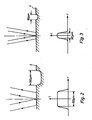
- FIG. 1 shows, a 3-stage scaled-down imaging of the electron source is carried out by means of magnetic lenses.
- a first long focal length lens 1 is combined with a second short focal length lens 2 for this purpose.
- the third lens 3 has a long focal length and enables the large working distance from the printing form surface 4; it corresponds to the main lens of the previously known electron beam gun and is combined with a dynamic lens 3a, as described in DE-AS 27 52 598.
- An equally dynamic lens 5 is arranged in the first long-focal lens 1. When this lens 5 is excited, the image width of the first long-focal lens 1 is changed by a small amount. The magnification of the lens combination 1/5 changes little.
- a numerical example may clarify this: B. the lens 1 triple, and if the lens 5 is not excited in it, the second short focal length lens 2 can be set so that it produces an image ratio of 1. If the lens 3 then produces an imaging ratio of 4, the overall reduction is equal to 12.
- the resulting beam path is shown with solid lines. If the lens 5 arranged in lens 1 is now excited, the first intermediate image moves closer to the lens combination 1/5. At the same time, the object width of the second short focal length lens 2 becomes larger. This means that the short focal length lens 2 now has an imaging scale of, for example, 3 with unchanged excitation. The overall scale of reduction of the arrangement has thus changed to 36.
- the resulting beam path is shown in dashed lines in Figure 1.
- an aperture diaphragm 7 is arranged behind the short focal length lens 2, there is also a modulation of the beam energy in addition to the modulation of the imaging scale.
- FIG. 2 The focus ratios at the point of action of the beam are shown in FIG. 2 for large cells, and in FIG. 3 for small cells.
- L denotes the beam power density and r denotes the radius at the point of action.
- the arrangement described enables a very rapid change in the imaging scale.
- the response time in the transition from strong to weak reduction and vice versa can be carried out with the arrangement according to the invention in approximately 1 f.1S.
- the excitation of the lens 5 is of the same order of magnitude as is required for the unsharpness of the beam described in DE-OS 29 47 444 during the engraving pause between two successive cells.
- the invention can be used to advantage in the engraving of printing forms with electron beams. It can also be used wherever material processing of any kind, such as welding, drilling, engraving, heating, etc. is carried out with charge carrier jets. In addition, it can also be used in the field of electron beam lithography.
Landscapes
- Engineering & Computer Science (AREA)
- Plasma & Fusion (AREA)
- Analytical Chemistry (AREA)
- Chemical & Material Sciences (AREA)
- Physics & Mathematics (AREA)
- Mechanical Engineering (AREA)
- Optics & Photonics (AREA)
- Manufacturing & Machinery (AREA)
- Manufacture Or Reproduction Of Printing Formes (AREA)
- Electron Beam Exposure (AREA)
- Preparing Plates And Mask In Photomechanical Process (AREA)
- Viewfinders (AREA)
- Radiation-Therapy Devices (AREA)
Claims (6)
Priority Applications (8)
| Application Number | Priority Date | Filing Date | Title |
|---|---|---|---|
| AT81108156T ATE24985T1 (de) | 1981-10-10 | 1981-10-10 | Elektronenstrahl-gravierverfahren und einrichtung zu seiner durchfuehrung. |
| DE8181108156T DE3175839D1 (en) | 1981-10-10 | 1981-10-10 | Electron beam engraving method and apparatus for carrying it out |
| EP81108156A EP0076868B1 (fr) | 1981-10-10 | 1981-10-10 | Procédé de gravure par rayons à électrons et dispositif pour sa réalisation |
| US06/423,176 US4471205A (en) | 1981-10-10 | 1982-09-24 | Electron beam engraving method and device for execution |
| SU823496070A SU1452471A3 (ru) | 1981-10-10 | 1982-09-28 | Способ гравировани электронным лучом растровых чеек различных размеров на поверхности печатной формы и устройство дл его осуществлени |
| DD82243803A DD204180A5 (de) | 1981-10-10 | 1982-10-05 | Elektronenstrahl-gravierverfahren und einrichtung zu seiner durchfuehrung |
| DK444082A DK444082A (da) | 1981-10-10 | 1982-10-07 | Elektronstraale-graveringsfremgangsmaade og apparat til dens gennemfoerelse |
| JP57176440A JPS5872450A (ja) | 1981-10-10 | 1982-10-08 | 電子ビ−ム−彫刻方法および装置 |
Applications Claiming Priority (1)
| Application Number | Priority Date | Filing Date | Title |
|---|---|---|---|
| EP81108156A EP0076868B1 (fr) | 1981-10-10 | 1981-10-10 | Procédé de gravure par rayons à électrons et dispositif pour sa réalisation |
Publications (2)
| Publication Number | Publication Date |
|---|---|
| EP0076868A1 EP0076868A1 (fr) | 1983-04-20 |
| EP0076868B1 true EP0076868B1 (fr) | 1987-01-14 |
Family
ID=8187949
Family Applications (1)
| Application Number | Title | Priority Date | Filing Date |
|---|---|---|---|
| EP81108156A Expired EP0076868B1 (fr) | 1981-10-10 | 1981-10-10 | Procédé de gravure par rayons à électrons et dispositif pour sa réalisation |
Country Status (8)
| Country | Link |
|---|---|
| US (1) | US4471205A (fr) |
| EP (1) | EP0076868B1 (fr) |
| JP (1) | JPS5872450A (fr) |
| AT (1) | ATE24985T1 (fr) |
| DD (1) | DD204180A5 (fr) |
| DE (1) | DE3175839D1 (fr) |
| DK (1) | DK444082A (fr) |
| SU (1) | SU1452471A3 (fr) |
Families Citing this family (7)
| Publication number | Priority date | Publication date | Assignee | Title |
|---|---|---|---|---|
| DE4102983A1 (de) * | 1990-09-28 | 1992-04-02 | Linotype Ag | Oberflaechenstruktur einer walze sowie verfahren und vorrichtung zur erzeugung der oberflaechenstruktur |
| DE4031547A1 (de) * | 1990-10-05 | 1992-04-09 | Hell Rudolf Dr Ing Gmbh | Verfahren und vorrichtung zur herstellung von texturwalzen |
| DE4039105C2 (de) * | 1990-12-07 | 1994-12-08 | Roland Man Druckmasch | Vorrichtung zur bildmäßigen Beschreibung einer Druckform |
| DE19624131A1 (de) * | 1996-06-17 | 1997-12-18 | Giesecke & Devrient Gmbh | Verfahren zur Herstellung von Prägeplatten |
| US20090168111A9 (en) * | 1999-09-01 | 2009-07-02 | Hell Gravure Systems Gmbh | Printing form processing with fine and coarse engraving tool processing tracks |
| DE10058990C2 (de) * | 2000-11-28 | 2003-03-06 | Heidelberger Druckmasch Ag | Vorrichtung zur Bestrahlung eines Objektes für eine Aufzeichnung eines visuellen Produktes |
| DE102004023021B4 (de) * | 2004-05-06 | 2009-11-12 | Pro-Beam Ag & Co. Kgaa | Verfahren zur ablativen Bearbeitung von Oberflächenbereichen |
Family Cites Families (8)
| Publication number | Priority date | Publication date | Assignee | Title |
|---|---|---|---|---|
| NL268860A (fr) * | 1959-04-17 | |||
| DE2111628A1 (de) * | 1971-03-11 | 1972-09-14 | Gruner & Jahr | Verfahren und Vorrichtung zum Herstellen von Druckformen,insbesondere Tiefdruckformen |
| DE2458370C2 (de) * | 1974-12-10 | 1984-05-10 | Dr.-Ing. Rudolf Hell Gmbh, 2300 Kiel | Energiestrahl-Gravierverfahren und Einrichtung zu seiner Durchführung |
| JPS5283177A (en) * | 1975-12-31 | 1977-07-11 | Fujitsu Ltd | Electron beam exposure device |
| DE2752598C3 (de) * | 1977-11-25 | 1981-10-15 | Dr.-Ing. Rudolf Hell Gmbh, 2300 Kiel | Verfahren zum Betrieb einer elektromagnetischen fokussierenden elektronen-optischen Linsenanordnung und Linsenanordnung hierfür |
| US4243866A (en) * | 1979-01-11 | 1981-01-06 | International Business Machines Corporation | Method and apparatus for forming a variable size electron beam |
| DE3008176C2 (de) * | 1979-03-07 | 1986-02-20 | Crosfield Electronics Ltd., London | Gravieren von Druckzylindern |
| DE2947444C2 (de) * | 1979-11-24 | 1983-12-08 | Dr.-Ing. Rudolf Hell Gmbh, 2300 Kiel | Elektronenstrahl-Gravierverfahren |
-
1981
- 1981-10-10 AT AT81108156T patent/ATE24985T1/de not_active IP Right Cessation
- 1981-10-10 EP EP81108156A patent/EP0076868B1/fr not_active Expired
- 1981-10-10 DE DE8181108156T patent/DE3175839D1/de not_active Expired
-
1982
- 1982-09-24 US US06/423,176 patent/US4471205A/en not_active Expired - Lifetime
- 1982-09-28 SU SU823496070A patent/SU1452471A3/ru active
- 1982-10-05 DD DD82243803A patent/DD204180A5/de unknown
- 1982-10-07 DK DK444082A patent/DK444082A/da not_active Application Discontinuation
- 1982-10-08 JP JP57176440A patent/JPS5872450A/ja active Granted
Also Published As
| Publication number | Publication date |
|---|---|
| JPS6255987B2 (fr) | 1987-11-24 |
| JPS5872450A (ja) | 1983-04-30 |
| EP0076868A1 (fr) | 1983-04-20 |
| SU1452471A3 (ru) | 1989-01-15 |
| ATE24985T1 (de) | 1987-01-15 |
| DD204180A5 (de) | 1983-11-16 |
| DE3175839D1 (en) | 1987-02-19 |
| US4471205A (en) | 1984-09-11 |
| DK444082A (da) | 1983-04-11 |
Similar Documents
| Publication | Publication Date | Title |
|---|---|---|
| DE2458370C2 (de) | Energiestrahl-Gravierverfahren und Einrichtung zu seiner Durchführung | |
| DE3924605C2 (de) | Rasterelektronenmikroskop | |
| DE3219573C2 (de) | Elektronenstrahlunterbrecher | |
| DE2555744B2 (de) | Magnetische linse | |
| DE1106893B (de) | Verfahren und Vorrichtung zur Herstellung eines elektronischen Bauelementes | |
| DE2702445A1 (de) | Korpuskularstrahloptisches geraet zur verkleinernden abbildung einer maske auf ein zu bestrahlendes praeparat | |
| DE2620262A1 (de) | Rechner-gesteuertes elektronenstrahllithographie-verfahren | |
| DE2459091C3 (de) | Strahlerzeugungssystem einer Kathodenstrahlröhre | |
| EP0076868B1 (fr) | Procédé de gravure par rayons à électrons et dispositif pour sa réalisation | |
| DE2719725C2 (de) | Einrichtung zur Elektronenstrahlerwärmung von Materialien | |
| DE3903277C2 (fr) | ||
| DE2418279C2 (de) | Elektronenstrahl-Abtastinstrument | |
| DE3919829C2 (de) | Elektronenkanonen-System mit Feldemission | |
| DE2704441A1 (de) | Vorrichtung und verfahren zur bestrahlung einer werkstueckflaeche | |
| EP0108375B1 (fr) | Procédé de contrôle de surfaces d'impression gravées à l'aide d'un faisceau électronique | |
| EP0169453A1 (fr) | Dispositif de circuit pour éviter les phénomènes de brûlure sur l'écran d'un indicateur visuel | |
| DE19915572A1 (de) | Immersionslinse und Elektronenstrahl-Projektionssystem zu deren Anwendung | |
| DE3213498C2 (fr) | ||
| DE2742264C3 (de) | Verfahren zur Abbildung eines Objektes mit geringer Vergrößerung mittels eines Korpuskularstrahlgeräts, insbesondere eines Elektronen-Mikroskops und Korpuskularstrahlgerät zur Durchführung des Verfahrens | |
| DE958743C (de) | Bildaufnahmeroehre | |
| DE3224871C2 (de) | Magnetische Elektronenlinse | |
| DE2805371A1 (de) | Elektronenstrahlgeraet mit strahlfleckformung | |
| DE2825900C2 (de) | Elektronenstrahlsystem einer Elektronenstrahlröhre | |
| DE2830696C2 (de) | Bildaufnahmevorrichtung | |
| DE2541245A1 (de) | Korpuskularstrahl-rastermikroskop |
Legal Events
| Date | Code | Title | Description |
|---|---|---|---|
| PUAI | Public reference made under article 153(3) epc to a published international application that has entered the european phase |
Free format text: ORIGINAL CODE: 0009012 |
|
| 17P | Request for examination filed |
Effective date: 19820626 |
|
| AK | Designated contracting states |
Designated state(s): AT BE CH DE FR GB IT LI NL SE |
|
| 17Q | First examination report despatched |
Effective date: 19860213 |
|
| GRAA | (expected) grant |
Free format text: ORIGINAL CODE: 0009210 |
|
| AK | Designated contracting states |
Kind code of ref document: B1 Designated state(s): AT BE CH DE FR GB IT LI NL SE |
|
| REF | Corresponds to: |
Ref document number: 24985 Country of ref document: AT Date of ref document: 19870115 Kind code of ref document: T |
|
| REF | Corresponds to: |
Ref document number: 3175839 Country of ref document: DE Date of ref document: 19870219 |
|
| ITF | It: translation for a ep patent filed |
Owner name: STUDIO TORTA SOCIETA' SEMPLICE |
|
| ET | Fr: translation filed | ||
| PG25 | Lapsed in a contracting state [announced via postgrant information from national office to epo] |
Ref country code: SE Effective date: 19871011 |
|
| PG25 | Lapsed in a contracting state [announced via postgrant information from national office to epo] |
Ref country code: LI Effective date: 19871031 Ref country code: CH Effective date: 19871031 Ref country code: BE Effective date: 19871031 |
|
| PLBE | No opposition filed within time limit |
Free format text: ORIGINAL CODE: 0009261 |
|
| STAA | Information on the status of an ep patent application or granted ep patent |
Free format text: STATUS: NO OPPOSITION FILED WITHIN TIME LIMIT |
|
| 26N | No opposition filed | ||
| BERE | Be: lapsed |
Owner name: DR.-ING. RUDOLF HELL G.M.B.H. Effective date: 19871031 |
|
| REG | Reference to a national code |
Ref country code: CH Ref legal event code: PL |
|
| PGFP | Annual fee paid to national office [announced via postgrant information from national office to epo] |
Ref country code: AT Payment date: 19910930 Year of fee payment: 11 |
|
| ITTA | It: last paid annual fee | ||
| PGFP | Annual fee paid to national office [announced via postgrant information from national office to epo] |
Ref country code: NL Payment date: 19911031 Year of fee payment: 11 |
|
| REG | Reference to a national code |
Ref country code: FR Ref legal event code: TP Ref country code: FR Ref legal event code: CA |
|
| PG25 | Lapsed in a contracting state [announced via postgrant information from national office to epo] |
Ref country code: AT Effective date: 19921010 |
|
| PG25 | Lapsed in a contracting state [announced via postgrant information from national office to epo] |
Ref country code: NL Effective date: 19930501 |
|
| NLV4 | Nl: lapsed or anulled due to non-payment of the annual fee | ||
| REG | Reference to a national code |
Ref country code: GB Ref legal event code: 732E |
|
| EUG | Se: european patent has lapsed |
Ref document number: 81108156.1 Effective date: 19880707 |
|
| REG | Reference to a national code |
Ref country code: GB Ref legal event code: 732E |
|
| REG | Reference to a national code |
Ref country code: FR Ref legal event code: TP |
|
| PGFP | Annual fee paid to national office [announced via postgrant information from national office to epo] |
Ref country code: GB Payment date: 19990921 Year of fee payment: 19 |
|
| PGFP | Annual fee paid to national office [announced via postgrant information from national office to epo] |
Ref country code: FR Payment date: 19991018 Year of fee payment: 19 |
|
| PGFP | Annual fee paid to national office [announced via postgrant information from national office to epo] |
Ref country code: DE Payment date: 19991116 Year of fee payment: 19 |
|
| PG25 | Lapsed in a contracting state [announced via postgrant information from national office to epo] |
Ref country code: GB Free format text: LAPSE BECAUSE OF NON-PAYMENT OF DUE FEES Effective date: 20001010 |
|
| GBPC | Gb: european patent ceased through non-payment of renewal fee |
Effective date: 20001010 |
|
| PG25 | Lapsed in a contracting state [announced via postgrant information from national office to epo] |
Ref country code: FR Free format text: LAPSE BECAUSE OF NON-PAYMENT OF DUE FEES Effective date: 20010629 |
|
| PG25 | Lapsed in a contracting state [announced via postgrant information from national office to epo] |
Ref country code: DE Free format text: LAPSE BECAUSE OF NON-PAYMENT OF DUE FEES Effective date: 20010703 |
|
| REG | Reference to a national code |
Ref country code: FR Ref legal event code: ST |