EP0075409A2 - Vorderradaufhängung für Strassenfahrzeuge - Google Patents
Vorderradaufhängung für Strassenfahrzeuge Download PDFInfo
- Publication number
- EP0075409A2 EP0075409A2 EP82304696A EP82304696A EP0075409A2 EP 0075409 A2 EP0075409 A2 EP 0075409A2 EP 82304696 A EP82304696 A EP 82304696A EP 82304696 A EP82304696 A EP 82304696A EP 0075409 A2 EP0075409 A2 EP 0075409A2
- Authority
- EP
- European Patent Office
- Prior art keywords
- front wheel
- wheel suspension
- bottom case
- orifice
- oil passage
- Prior art date
- Legal status (The legal status is an assumption and is not a legal conclusion. Google has not performed a legal analysis and makes no representation as to the accuracy of the status listed.)
- Granted
Links
- 239000000725 suspension Substances 0.000 title claims abstract description 25
- 230000008602 contraction Effects 0.000 claims abstract description 10
- 238000013016 damping Methods 0.000 claims abstract description 6
- 230000000452 restraining effect Effects 0.000 claims description 8
- 239000012530 fluid Substances 0.000 claims 1
- 230000035939 shock Effects 0.000 abstract description 10
- 230000000694 effects Effects 0.000 abstract description 5
- 239000006096 absorbing agent Substances 0.000 abstract description 3
- 230000006835 compression Effects 0.000 description 7
- 238000007906 compression Methods 0.000 description 7
- 238000005192 partition Methods 0.000 description 6
- 238000006073 displacement reaction Methods 0.000 description 2
- 230000005484 gravity Effects 0.000 description 2
- 239000002184 metal Substances 0.000 description 2
Images

Classifications
-
- B—PERFORMING OPERATIONS; TRANSPORTING
- B62—LAND VEHICLES FOR TRAVELLING OTHERWISE THAN ON RAILS
- B62K—CYCLES; CYCLE FRAMES; CYCLE STEERING DEVICES; RIDER-OPERATED TERMINAL CONTROLS SPECIALLY ADAPTED FOR CYCLES; CYCLE AXLE SUSPENSIONS; CYCLE SIDE-CARS, FORECARS, OR THE LIKE
- B62K25/00—Axle suspensions
- B62K25/04—Axle suspensions for mounting axles resiliently on cycle frame or fork
- B62K25/06—Axle suspensions for mounting axles resiliently on cycle frame or fork with telescopic fork, e.g. including auxiliary rocking arms
- B62K25/08—Axle suspensions for mounting axles resiliently on cycle frame or fork with telescopic fork, e.g. including auxiliary rocking arms for front wheel
-
- B—PERFORMING OPERATIONS; TRANSPORTING
- B60—VEHICLES IN GENERAL
- B60G—VEHICLE SUSPENSION ARRANGEMENTS
- B60G17/00—Resilient suspensions having means for adjusting the spring or vibration-damper characteristics, for regulating the distance between a supporting surface and a sprung part of vehicle or for locking suspension during use to meet varying vehicular or surface conditions, e.g. due to speed or load
- B60G17/06—Characteristics of dampers, e.g. mechanical dampers
- B60G17/08—Characteristics of fluid dampers
Definitions
- This invention relates to front wneel suspensions of road vehicles such as motorcycles. It is particularly concerned with front wheel suspensions that include a telescopic hydraulic shock absorber mechanism providing an anti-dive function upon braking.
- a telescopic front fork including two sets of axially slidable inner and outer tubular members, each set of' these tubular members being constituted by a fork pipe and a bottom case, and a hydraulic system interposed between the two tubular members for providing a shock absorbing action.
- a damping force acting in a direction to contract the front fork when the contraction restraining mechanism is operative is caused to be substantially constant due to a reactive force against the braking effect, resulting in difficulty in attaining an appropriate adjustment.
- a road vehicle front wheel suspension comprising two sets of inner and outer tubular members, each set consisting of a fork pipe axially slidable in a bottom case, a hydraulic system interposed between the tubular members of each set for providing a damping action, and a contraction restraining mechanism operable under vehicle braking to intercept a main communicating oil passage between the fork pipe and the bottom case to restrain axial contracting motion between the fork pipe and the bottom case; characterised in that a bypass oil passage communicating the inner and outer tubular members is provided in the bottom case, and an adjustable orifice means is provided in this bypass oil passage.
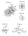
- a telescopic front fork 1 for a motor cycle which includes two bottom cases 2 (only one is shown) and twofork pipes 3 (only one is shown) fitted for axial sliding motion in respective bottom cases 2.
- a front axle 6 is held fast on the lower part of each bottom case 2 by means of an axle holder 4 and bolts 5.
- a front wheel 7 is mounted for rotation on the front wheel axle 6 via a bearing (not shown).
- Annular brake disks 8 are mounted fast on opposite sides of a front wheel hub (not shown), and a brake caliper 9 is disposed to extend across the brake disks 8 over the outer diameters thereof.
- the brake caliper 9 is mounted on a caliper bracket 12 which is supported for pivotal, motion about a shaft 11 mounted on a boss 10 that extends rearwardly from the bottom case 2.
- a lower end of a seat pipe 14 is secured in fast and concentrical relationship with the bottom case 2 by means of a bolt 19 with a metal partition member 17 interposed between them.
- a piston 15 formed integrally at the opposite upper end of the seat pipe 14 is fitted in an inner circumferential surface of the fork pipe 3 of the telescopic front fork 1 in a sliding and oil-tight relationship therewith.
- a compression coil spring 20 is interposed between an upper end (not shown) of the fork pipe 3 and an upper end of the piston 15 within the fork pipe 3 so that, when there is no compressing force applied between the fork pipe 3 and the bottom case 2 of the telescopic front fork 1, the front fork 1 is held in an extended position due to the biassing force of the compressing coil spring 20.
- a check valve 24 placed on the top face of the valve seat 22 has an outer diameter smaller than the inner diameter of the inner tube 21 and an inner diameter substantially conforming to the outer diameter of the seat pipe 14.
- the check valve 24 has a plurality of notches 25 formed along its inner circumferential edge thereof as seen in Figure 4, each serving as an orifice, and also has a plurality of projections 26 formed on its top face along a circumference thereof. The check valve 24 is positioned such that the projections 26 thereof are engaged and held down by the inner projections of the spring plates 23, respectively, as shown in Figure 3.
- the inner tube 21 has, at the top end thereof, an inwardly extending flange 21a (having an inner diameter greater than the outer diameter of the seat pipe 14), and a compression coil spring 28 having a predetermined height is placed- on an upper face of the flange 21a of the inner tube 21 so that a damping action is obtained by the biassing force of this compression coil spring 28 when an extending force is applied between the fork pipe 3 and the bottom case 2 to move the check valve 24 near to the piston 15.
- the oil pressure generating chamber 29 defined by the bottom case 2, the seat pipe 14 and the partition member 17 is connected to a communicating chamber 30 defined by the bottom case 2 and the partition member 17 by way of a contraction restraining mechanism 40 as hereinafter described.
- the communicating chamber 30 is in turn connected to a reservoir chamber 31 defined by the seat pipe 14 and the fork pipe 3 by way of openings in the partition member 17 and further openings in the seat pipe 14.
- a check valve mechanism 35 is additionally provided on the top end of the partition member 17.
- This mechanism 35 includes a metal spring seat member 32 fitted on and secured to the seat pipe 14, a slidable member 33, and a compression coil spring 34 interposed between the spring seat member 32 and the slidable member 33.
- the contraction restraining mechanism 40 is disposed rearwardly of the bottom case 2, below the brake caliper bracket supporting boss 10, ar-d includes a casing 41, an anti-dive piston 48 fitted in an oil-tight and sliding relationship in a cylinder chamber 43 in the casing 41 and normally urged in a direction away from the bottom case 2 by a spring 63, a rotatable adjusting orifice bolt 50 fitted in a bypass passage 45 which has one end communicated with an opening 49 of the piston 48, and a stopper mechanism 56 for fixture of the orifice bolt 50.
- the casing 41 has formed therein a main passage 42 which connects an opening 61 facing the oil pressure generating chamber 29 within the bottom case 2 to another opening 62 facing the communicating chamber 30, the aforementioned cylinder chamber 43 which is opposed to the opening 61, a shaft receiving hole 44 which communicates with the top of the cylinder chamber 43 and has a shaft 13 loosely fitted therein which is mounted on the caliper bracket 12, the bypass passage 45 which communicates the opening 49 of the piston 48 with the main passage 42, a drain bolt hole 46 which communicates with the bypass passage 45 (a drain bolt 60 being screwed into the drain bolt hole 46), and a stopper chamber 47 which contains therein the stopper mechanism 56 for fixture of the orifice bolt 50.
- the rotatable adjusting orifice bolt 50 has formed therein a centre passage 51, radially extending communicating passages 52, 53 and 54 of different diameters which are disposed in an angularly spaced relationship of 90° from each other and communicate with the cel ,re passage 51, and a recess 55 which has no communication with the centre passage 51 and which is opposite the passage 53 and hence is spaced 90° from each of the passages 52 and 54.
- the stopper mechanism 56 for fixture of the orifice bolt 50 includes an adjusting bolt 57 for backward and forward adjustment, an engaging member in the form of a ball 58 disposed for engagement with the communicating passages 52, 53, 54 and the recess 55, and a compression coil spring 59 interposed between the adjusting bolt 57 and the ball 58.
- the telescopic front fork 1 can extend itself rapidly since the anti-dive piston 48 is spaced from the bottom case 2 by the biassing force of the coil spring 63 and also pressure oil in the reservoir chamber 31 takes a path of low flow resistance, flowing from the opening 16 into the oil pressure generating chamber 29 by way of the check valve 35.
- flow resistance can be selectively preset to four different levels by angularly rotating the rotatable adjusting orifice bolt 50 through 90 degrees a suitable number of times, using a screw driver or a similar tool, to bring one of the communication passages 52, 53, 54, or the recess 55, of the orifice bolt 50 into register with the bypass passage 45.
- a desired anti-dive characteristic can be obtained thereby.
- suspension illustrated and described is applied to a motorcycle, it can be applied likewise to an two-tricycle which has a front wheel and auto rear wheels.
Landscapes
- Engineering & Computer Science (AREA)
- Mechanical Engineering (AREA)
- Axle Suspensions And Sidecars For Cycles (AREA)
- Fluid-Damping Devices (AREA)
Applications Claiming Priority (2)
| Application Number | Priority Date | Filing Date | Title |
|---|---|---|---|
| JP148029/81 | 1981-09-19 | ||
| JP56148029A JPS5849586A (ja) | 1981-09-19 | 1981-09-19 | 自動二輪車等の前輪懸架装置 |
Publications (3)
| Publication Number | Publication Date |
|---|---|
| EP0075409A2 true EP0075409A2 (de) | 1983-03-30 |
| EP0075409A3 EP0075409A3 (en) | 1983-11-30 |
| EP0075409B1 EP0075409B1 (de) | 1989-06-07 |
Family
ID=15443516
Family Applications (1)
| Application Number | Title | Priority Date | Filing Date |
|---|---|---|---|
| EP82304696A Expired EP0075409B1 (de) | 1981-09-19 | 1982-09-08 | Vorderradaufhängung für Strassenfahrzeuge |
Country Status (7)
| Country | Link |
|---|---|
| US (1) | US4515384A (de) |
| EP (1) | EP0075409B1 (de) |
| JP (1) | JPS5849586A (de) |
| AU (1) | AU535616B2 (de) |
| CA (1) | CA1178213A (de) |
| DE (1) | DE3279752D1 (de) |
| ES (1) | ES8308508A1 (de) |
Families Citing this family (20)
| Publication number | Priority date | Publication date | Assignee | Title |
|---|---|---|---|---|
| JPS5975882A (ja) * | 1982-10-25 | 1984-04-28 | カヤバ工業株式会社 | 二輪車用緩衝器 |
| JPS59187584U (ja) * | 1983-05-31 | 1984-12-12 | 株式会社 昭和製作所 | フロントフオ−クのアンチダイブ機構 |
| JPS60252084A (ja) * | 1984-05-26 | 1985-12-12 | 本田技研工業株式会社 | 車輪角減速度センサの支持・駆動装置 |
| JPS60252054A (ja) * | 1984-05-30 | 1985-12-12 | Honda Motor Co Ltd | 車両の制動装置 |
| JPS6112459A (ja) * | 1984-06-26 | 1986-01-20 | Honda Motor Co Ltd | 自動二輪車の後輪制動装置 |
| US4807860A (en) * | 1984-06-28 | 1989-02-28 | Simons Stephen W | Motorcycle front fork anti-cavity damping system |
| JPS61113584A (ja) * | 1984-11-06 | 1986-05-31 | 本田技研工業株式会社 | 二輪車の前輪用アンチロツク制動装置 |
| US4625985A (en) * | 1985-04-15 | 1986-12-02 | Honda Giken Kogyo Kabushiki Kaisha | Anti dive devices for motorcycles |
| US4743045A (en) * | 1985-06-14 | 1988-05-10 | Honda Giken Kogyo Kabushiki Kaisha | Antidive apparatus for a vehicle |
| US4770473A (en) * | 1985-08-21 | 1988-09-13 | Honda Giken Kogyo Kabushiki Kaisha | Brake device for vehicles |
| JPS6246750A (ja) * | 1985-08-23 | 1987-02-28 | Honda Motor Co Ltd | 車両の制動装置 |
| US4971344A (en) * | 1989-01-04 | 1990-11-20 | Rockshox, Inc. | Bicycle with a front fork wheel suspension |
| EP1144211A2 (de) | 1998-12-18 | 2001-10-17 | General Dynamics Ordnance and Tactical Systems, Inc. | Motorradaufhängungskomponenten |
| CZ303654B6 (cs) * | 2007-03-22 | 2013-01-30 | Sithold S.R.O. | Zarízení na zvýsení prítlaku kola automobilu k vozovce |
| JP6122921B2 (ja) * | 2015-08-31 | 2017-04-26 | 本田技研工業株式会社 | 鞍乗り型車両 |
| CN105564183B (zh) * | 2016-03-01 | 2018-01-30 | 深圳市聚马新能源汽车科技有限公司 | 汽车减震器控制系统 |
| USD826796S1 (en) * | 2016-11-14 | 2018-08-28 | Showa Corporation | Axle holder for motorcycle |
| TWM574582U (zh) * | 2018-11-05 | 2019-02-21 | 曾智弘 | 用於機車之前叉避震器 |
| JP1732558S (ja) * | 2022-03-18 | 2022-12-19 | 自動二輪車用アクスルホルダ | |
| CN116044950A (zh) * | 2022-12-25 | 2023-05-02 | 重庆宗申创新技术研究院有限公司 | 摩托车减振器 |
Family Cites Families (16)
| Publication number | Priority date | Publication date | Assignee | Title |
|---|---|---|---|---|
| US3103993A (en) * | 1959-12-09 | 1963-09-17 | Houdaille Industries Inc | Linear hydraulic damper |
| GB1006265A (en) * | 1962-11-24 | 1965-09-29 | Armstrong Patents Co Ltd | Improvements in and relating to adjustable hydraulic shock absorbers |
| GB1232236A (de) * | 1968-05-25 | 1971-05-19 | ||
| US3731770A (en) * | 1971-05-19 | 1973-05-08 | Ace Controls | Adjustable shock absorber |
| GB1354385A (en) * | 1971-11-16 | 1974-06-05 | Armstrong Patents Co Ltd | Telescopic hydraulic shock absorbers |
| US3889934A (en) * | 1973-12-19 | 1975-06-17 | Houdaille Industries Inc | Hydraulic buffer |
| FR2291417A1 (fr) * | 1974-11-14 | 1976-06-11 | Dispositifs Electr Meca Sa | Perfectionnements aux amortisseurs hydrauliques |
| US3912054A (en) * | 1974-11-25 | 1975-10-14 | Brian K Fabre | Valve replacement assembly for motorcycle front forks |
| US3989261A (en) * | 1975-07-24 | 1976-11-02 | Honda Giken Kogyo Kabushiki Kaisha | Motorcycle front-wheel suspension with means for restraint of compression of a telescopic front upon braking |
| JPS5833031Y2 (ja) * | 1976-05-14 | 1983-07-22 | 本田技研工業株式会社 | 自動二輪車等のフロントフオ−ク |
| DE2723102A1 (de) * | 1977-05-21 | 1978-11-23 | Walter Holzer | Gasfeder mit variabler ausschubgeschwindigkeit |
| US4159756A (en) * | 1978-01-17 | 1979-07-03 | Kayaba K.K. | Adjusting device for damping force of rear shock-absorbers of motorcycles |
| GB2016647B (en) * | 1978-02-06 | 1982-10-20 | Tokico Ltd | Adjusting hydraulic damper |
| JPS54138249A (en) * | 1978-04-17 | 1979-10-26 | Kayaba Industry Co Ltd | Shock absorber for twoowheel barrow |
| US4278266A (en) * | 1979-07-20 | 1981-07-14 | Honda Giken Kogyo Kabushiki Kaisha | Front fork construction for motorcycle |
| JPS6033705B2 (ja) * | 1980-11-04 | 1985-08-05 | 株式会社昭和製作所 | オ−トバイのフロントフオ−ク |
-
1981
- 1981-09-19 JP JP56148029A patent/JPS5849586A/ja active Granted
-
1982
- 1982-08-30 AU AU87843/82A patent/AU535616B2/en not_active Ceased
- 1982-09-08 EP EP82304696A patent/EP0075409B1/de not_active Expired
- 1982-09-08 DE DE8282304696T patent/DE3279752D1/de not_active Expired
- 1982-09-10 ES ES515650A patent/ES8308508A1/es not_active Expired
- 1982-09-15 US US06/418,291 patent/US4515384A/en not_active Expired - Fee Related
- 1982-09-20 CA CA000411762A patent/CA1178213A/en not_active Expired
Also Published As
| Publication number | Publication date |
|---|---|
| DE3279752D1 (en) | 1989-07-13 |
| JPS5849586A (ja) | 1983-03-23 |
| AU8784382A (en) | 1983-03-31 |
| CA1178213A (en) | 1984-11-20 |
| EP0075409A3 (en) | 1983-11-30 |
| AU535616B2 (en) | 1984-03-29 |
| ES515650A0 (es) | 1983-09-16 |
| US4515384A (en) | 1985-05-07 |
| ES8308508A1 (es) | 1983-09-16 |
| JPS624277B2 (de) | 1987-01-29 |
| EP0075409B1 (de) | 1989-06-07 |
Similar Documents
| Publication | Publication Date | Title |
|---|---|---|
| EP0075409A2 (de) | Vorderradaufhängung für Strassenfahrzeuge | |
| EP3628888B1 (de) | Fahrradstossdämpfer | |
| US7520372B2 (en) | Inertia valve vehicle suspension assembly | |
| EP1754909B1 (de) | Positionsempfindlicher Dämpfer | |
| US5803482A (en) | Shock absorber for automotive suspension | |
| US9963191B2 (en) | Bicycle damper | |
| US20030075402A1 (en) | Inertia valve shock absorber | |
| JP3513423B2 (ja) | ショックアブソーバ用の受動型減衰装置 | |
| JPH11315876A (ja) | ダンパ | |
| US7914031B2 (en) | Bicycle damper | |
| WO2005033546A1 (en) | Extra support area for valve disc | |
| US8002092B2 (en) | Bicycle damper | |
| JPS621871B2 (de) | ||
| CA2409811A1 (en) | Shock absorber with a gas chamber on the rebound side of a piston | |
| EP1947365A1 (de) | Trägheitsventil für ein Fahrrad | |
| WO1999058392A1 (en) | Damping and spring system for suspension system | |
| JP2601010Y2 (ja) | 自転車用フロントフォークのダンパ装置 | |
| JP2004100785A (ja) | 油圧緩衝装置の懸架スプリング支持装置 | |
| JPH0826913B2 (ja) | 自動2輪車のフロントフォーク | |
| JP3080213B2 (ja) | 油圧緩衝器 | |
| JP2005147210A (ja) | 車両の油圧緩衝装置 | |
| JP2024129779A (ja) | ダンパおよびフロントフォーク | |
| JP2000145864A (ja) | 油圧緩衝器 | |
| TW202545770A (zh) | 自行車前叉 | |
| WO2024190240A1 (ja) | ダンパおよびフロントフォーク |
Legal Events
| Date | Code | Title | Description |
|---|---|---|---|
| PUAI | Public reference made under article 153(3) epc to a published international application that has entered the european phase |
Free format text: ORIGINAL CODE: 0009012 |
|
| AK | Designated contracting states |
Designated state(s): DE FR GB IT |
|
| PUAL | Search report despatched |
Free format text: ORIGINAL CODE: 0009013 |
|
| AK | Designated contracting states |
Designated state(s): DE FR GB IT |
|
| RHK1 | Main classification (correction) |
Ipc: B62K 25/08 |
|
| 17P | Request for examination filed |
Effective date: 19831215 |
|
| GRAA | (expected) grant |
Free format text: ORIGINAL CODE: 0009210 |
|
| AK | Designated contracting states |
Kind code of ref document: B1 Designated state(s): DE FR GB IT |
|
| REF | Corresponds to: |
Ref document number: 3279752 Country of ref document: DE Date of ref document: 19890713 |
|
| ITF | It: translation for a ep patent filed | ||
| ET | Fr: translation filed | ||
| PLBE | No opposition filed within time limit |
Free format text: ORIGINAL CODE: 0009261 |
|
| STAA | Information on the status of an ep patent application or granted ep patent |
Free format text: STATUS: NO OPPOSITION FILED WITHIN TIME LIMIT |
|
| 26N | No opposition filed | ||
| PGFP | Annual fee paid to national office [announced via postgrant information from national office to epo] |
Ref country code: GB Payment date: 19910805 Year of fee payment: 10 |
|
| PGFP | Annual fee paid to national office [announced via postgrant information from national office to epo] |
Ref country code: FR Payment date: 19910906 Year of fee payment: 10 |
|
| ITTA | It: last paid annual fee | ||
| PGFP | Annual fee paid to national office [announced via postgrant information from national office to epo] |
Ref country code: DE Payment date: 19910930 Year of fee payment: 10 |
|
| PG25 | Lapsed in a contracting state [announced via postgrant information from national office to epo] |
Ref country code: GB Effective date: 19920908 |
|
| GBPC | Gb: european patent ceased through non-payment of renewal fee |
Effective date: 19920908 |
|
| PG25 | Lapsed in a contracting state [announced via postgrant information from national office to epo] |
Ref country code: FR Effective date: 19930528 |
|
| PG25 | Lapsed in a contracting state [announced via postgrant information from national office to epo] |
Ref country code: DE Effective date: 19930602 |
|
| REG | Reference to a national code |
Ref country code: FR Ref legal event code: ST |
|
| APAH | Appeal reference modified |
Free format text: ORIGINAL CODE: EPIDOSCREFNO |