EP0074484A2 - Procédé et dispositif pour l'emmagasinage de points choisis d'une ligne à copier d'une machine pour le meulage de formes projetées - Google Patents
Procédé et dispositif pour l'emmagasinage de points choisis d'une ligne à copier d'une machine pour le meulage de formes projetées Download PDFInfo
- Publication number
- EP0074484A2 EP0074484A2 EP82106938A EP82106938A EP0074484A2 EP 0074484 A2 EP0074484 A2 EP 0074484A2 EP 82106938 A EP82106938 A EP 82106938A EP 82106938 A EP82106938 A EP 82106938A EP 0074484 A2 EP0074484 A2 EP 0074484A2
- Authority
- EP
- European Patent Office
- Prior art keywords
- projection
- marking element
- shape line
- carrier
- grinding wheel
- Prior art date
- Legal status (The legal status is an assumption and is not a legal conclusion. Google has not performed a legal analysis and makes no representation as to the accuracy of the status listed.)
- Granted
Links
- 238000000034 method Methods 0.000 title claims abstract description 13
- 238000006073 displacement reaction Methods 0.000 description 3
- 238000003754 machining Methods 0.000 description 2
Images
Classifications
-
- B—PERFORMING OPERATIONS; TRANSPORTING
- B24—GRINDING; POLISHING
- B24B—MACHINES, DEVICES, OR PROCESSES FOR GRINDING OR POLISHING; DRESSING OR CONDITIONING OF ABRADING SURFACES; FEEDING OF GRINDING, POLISHING, OR LAPPING AGENTS
- B24B17/00—Special adaptations of machines or devices for grinding controlled by patterns, drawings, magnetic tapes or the like; Accessories therefor
- B24B17/04—Special adaptations of machines or devices for grinding controlled by patterns, drawings, magnetic tapes or the like; Accessories therefor involving optical auxiliary means, e.g. optical projection form grinding machines
- B24B17/06—Special adaptations of machines or devices for grinding controlled by patterns, drawings, magnetic tapes or the like; Accessories therefor involving optical auxiliary means, e.g. optical projection form grinding machines combined with electrical transmission means, e.g. controlled by photoelectric cells
-
- B—PERFORMING OPERATIONS; TRANSPORTING
- B23—MACHINE TOOLS; METAL-WORKING NOT OTHERWISE PROVIDED FOR
- B23Q—DETAILS, COMPONENTS, OR ACCESSORIES FOR MACHINE TOOLS, e.g. ARRANGEMENTS FOR COPYING OR CONTROLLING; MACHINE TOOLS IN GENERAL CHARACTERISED BY THE CONSTRUCTION OF PARTICULAR DETAILS OR COMPONENTS; COMBINATIONS OR ASSOCIATIONS OF METAL-WORKING MACHINES, NOT DIRECTED TO A PARTICULAR RESULT
- B23Q17/00—Arrangements for observing, indicating or measuring on machine tools
- B23Q17/24—Arrangements for observing, indicating or measuring on machine tools using optics or electromagnetic waves
Definitions
- the invention relates to a method for storing selected points of a target shape line recorded on the projection screen of a projection shape grinding machine for controlling the position of the grinding wheel when grinding a contour corresponding to the target shape line into a workpiece.
- a grinding wheel which can be controlled in its position and a workpiece to be machined by it are imaged in the area of engagement via a projection beam path, enlarged on a projection screen, over which a transparent support is placed, on which a nominal shape line is recorded.
- the grinding wheel can be controlled in such a way that the workpiece is ground according to the nominal shape line. This can be followed precisely on the projection screen, since the boundary line between dark (workpiece) and bright (continuous light) ideally coincides with the target shape line.
- the respective position of the grinding wheel can be determined by means of an electronic control, for example by means of a CNC control which, for example, moves servo motors associated with the slide of a cross table, the carrier holding the grinding wheel.
- the invention has for its object to provide a method and an apparatus with which the input of a target shape curve in the control of a projection shape grinding machine can be accelerated and its accuracy can be improved.
- This object is achieved according to the invention by moving the image of a marking element attached to the carrier of the grinding wheel onto the projection screen by moving the carrier along the nominal shape line and storing the position of the carrier when the silhouette of the marking element is at the selected points on the projection screen Target shape line shows.
- this object is achieved according to the invention in that a marking element is fastened to the carrier receiving the grinding wheel of a projection shape grinding machine and can be imaged on the projection screen by means of the projection device.
- the marking element has a precisely defined position with respect to the point of engagement of the grinding wheel, so that when the marking element is depicted on the projection screen, for example on the starting point of the desired shape line, the exact position of the grinding wheel relative to the starting point of the contour to be actually machined into the workpiece is known.
- the grinding wheel can thus be moved exactly into the starting point of the contour to be ground by a precisely known displacement of the grinding wheel, which corresponds to the distance between the grinding wheel and the marking element.
- any further point which is specially marked on the nominal shape line for example by making holes in the carrier receiving the nominal shape curve.
- the marking element on the projection screen points to such a selected point
- the position data of the carrier corresponding to this position are stored, and this method is carried out over a larger number of selected points along the nominal shape line until the essential properties of the nominal shape line in the form of numerical data in the control unit are stored.
- the extremely large position of the carrier can be determined by the strong enlargement of the projection beam path, so that extremely high accuracy is obtained.
- the recording of the nominal shape line can be carried out in a very simple manner by adjusting the movement of the carrier by hand, as the operators of projection shape grinding machines are also used to directly work on workpieces.
- the marking element can be moved between a first position in which it dips into the beam path of the projection device and a second position in which it is removed from the beam path. In the second position, the marking element does not interfere with the machining process.
- the marking element can preferably be movable between the two positions by means of an electric motor or by means of a mechanical drive, it being advantageous if this drive can be actuated by the control itself.
- the Markierun g selement is a holder having a holds transparent reticle with intersecting lines or a partially or not translucent plate with a small hole more transparent to the projection light, the diameter of which is preferably 0.1 mm.
- the position of the marking element can be read particularly precisely on the projection screen; with a fifty-fold enlargement of the projection beam path and a hole in an opaque disk with a diameter of 0.1 mm, a positioning accuracy of the order of magnitude of 1 to 2 ⁇ m is obtained.
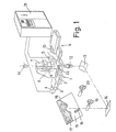
- a carrier 6 is arranged on the upper carriage 3, which carries a holder 7 which can be displaced in the vertical direction and on which one horizontal shaft a grinding wheel 8 is rotatably and motor-driven mounted.
- a second cross table 9 carries the workpiece 10 to be machined, which can be brought into engagement with the grinding wheel by shifting one of the two cross tables or both cross tables.
- the point of engagement is thrown onto a projection screen 15 by means of a projection beam path, which comprises a light source 11, a projection objective 12 and two deflection mirrors 13 and 14, on which the image 16 of the grinding wheel and the image 17 of the workpiece are shown.
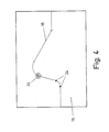
- a target shape curve 18 is recorded on the projection screen either directly or by means of a transparent support placed thereon, which marks the contour which the workpiece is to have after machining (FIG. 4).
- the slides 2 and 3 of the cross table 1 can be controlled either manually using handwheels 19 and 2o or via a CNC control 21 and the servomotors 4 and 5.
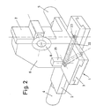
- a holder 22 which can be pivoted about a vertical axis and has an opening 23 at its free end, is also mounted in the plates 24 of various configurations event can be inserted ( Figure 2).
- the holder By means of an electric motor drive 25, the holder can be pivoted into a first position, shown in solid lines in FIG. 2, in which the opening with the inserted plate 24 is arranged in the projection beam path. In a second position, shown in broken lines in FIG. 2, the opening 23 is pivoted out of the projection beam path.
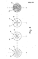
- FIG. 3 shows some possible designs of the plate 24.
- the plates A, B and C are transparent to the projection light and have lines which make the center 27 of the plates clear. In plate A, this is done by two lines 27 perpendicular to each other and circles concentrically surrounding the center 28.
- In embodiment B four lines 29, each rotated by 45 ° with respect to one another, intersect in a center point 30.
- two pairs of marking lines 31, which are perpendicular to one another, are provided and intersect in a center point 32.
- the exemplary embodiment D represents a plate which is partially or not at all transparent to the projection light and which has a small opening 33 in the center, the diameter of which is, for example, 0.1 mm.
- lines 27, 29 and 31 of the plates according to exemplary embodiment-A, B and C are thrown as image 26 onto the projection screen, so that the position of the respective center 28, 30 and 32 relative to the nominal shape line 18 can be determined exactly can.
- the image of the opening 33 appears as a bright point in a dark environment and must therefore also be located precisely.
- the target shape line 18 arranged on the projection screen is marked at different points so that selected points 34 are obtained.
- the cross table 1 is adjusted by means of the handwheels 19 and 20 so that the image 26 of the marking element (plate 24) lies exactly at the beginning of the nominal shape curve with its center.
- the corresponding position of the two carriages 2 and 3 is then saved.
- the center of the image 26 is then made to coincide with other selected points 34 by actuating the handwheels 19 and 20, the coordinates of the slide positions of the cross table 1 being stored each time.
- the ends of straight or circular curved lines or kinks between two straight areas can serve as selected points, for example. As soon as the position of these selected points is known to the control, it can calculate the exact line course between the selected points based on a previously entered program.
- the controller 21 then moves the slides 2 and 3 of the cross table 1 and thus the grinding wheel 8, so that a corresponding contour is ground into the workpiece 10 held on the cross table 9.
- the accuracy of the determination of the coordinates of the selected points is extremely high in this method, since the marking element is greatly enlarged by the projection beam path. Furthermore, the method for the operating personnel is easy and can be carried out in a short time, because the cross table 1 is moved by means of the handwheels 19 and 20 in the same way as is the case with manual grinding of workpieces.
- the embodiment D of the plate 24 shown in FIG. 3 with the central hole is particularly well suited for an automatic displacement of the slides 2 and 3 of the cross table 1 when storing the data corresponding to the selected points.
- the position of the image 26 can be scanned easily by means of a photocell which, instead of the handwheels, moves the carriages 2 and 3 of the cross table 1 until the image of the illuminated central opening 33 coincides with the selected point 34, which - as mentioned - can be generated by piercing the target curve, so that this point is also lighter than the adjacent areas of the target shape curve.
- the diameter of the image of the opening 33 corresponds to the line width of the nominal shape line.
Landscapes
- Engineering & Computer Science (AREA)
- Mechanical Engineering (AREA)
- Physics & Mathematics (AREA)
- Optics & Photonics (AREA)
- Grinding And Polishing Of Tertiary Curved Surfaces And Surfaces With Complex Shapes (AREA)
- Numerical Control (AREA)
Applications Claiming Priority (2)
| Application Number | Priority Date | Filing Date | Title |
|---|---|---|---|
| DE3136241A DE3136241C2 (de) | 1981-09-12 | 1981-09-12 | Verwendung eines mit der Schleifscheibe einer NC-repetiergesteuerten Projektionsformenschleifmaschine verfahrbaren Tastelements und Tastelement für diese Verwendung |
| DE3136241 | 1981-09-12 |
Publications (3)
| Publication Number | Publication Date |
|---|---|
| EP0074484A2 true EP0074484A2 (fr) | 1983-03-23 |
| EP0074484A3 EP0074484A3 (en) | 1983-06-01 |
| EP0074484B1 EP0074484B1 (fr) | 1986-02-19 |
Family
ID=6141501
Family Applications (1)
| Application Number | Title | Priority Date | Filing Date |
|---|---|---|---|
| EP82106938A Expired EP0074484B1 (fr) | 1981-09-12 | 1982-07-31 | Procédé et dispositif pour l'emmagasinage de points choisis d'une ligne à copier d'une machine pour le meulage de formes projetées |
Country Status (4)
| Country | Link |
|---|---|
| US (1) | US4489522A (fr) |
| EP (1) | EP0074484B1 (fr) |
| JP (1) | JPH0664487B2 (fr) |
| DE (2) | DE3136241C2 (fr) |
Cited By (2)
| Publication number | Priority date | Publication date | Assignee | Title |
|---|---|---|---|---|
| EP0366053A3 (fr) * | 1988-10-28 | 1991-03-06 | Michael Weinig Aktiengesellschaft | Dispositif de fabrication de gabarit de profilé |
| CN118650184A (zh) * | 2024-08-21 | 2024-09-17 | 四川鑫牛重型钢结构有限责任公司 | 一种对钢板进行钻孔加工的装置 |
Families Citing this family (14)
| Publication number | Priority date | Publication date | Assignee | Title |
|---|---|---|---|---|
| US4570385A (en) * | 1983-06-27 | 1986-02-18 | Fox Grinders, Inc. | Computer controlled workpiece finishing apparatus |
| DE3327117C2 (de) * | 1983-07-27 | 1986-02-13 | Dr. Johannes Heidenhain Gmbh, 8225 Traunreut | Verfahren zum zweidimensionalen Darstellen von dreidimensionalen Gebilden |
| JPH0696220B2 (ja) * | 1983-11-01 | 1994-11-30 | ワシノ機械株式会社 | 光倣い研削装置における研削加工方法 |
| JPH0641091B2 (ja) * | 1983-11-10 | 1994-06-01 | ワシノ機械株式会社 | 研削装置 |
| US4630214A (en) * | 1984-04-13 | 1986-12-16 | Moore Special Tool Co., Ltd. | Jig grinder with automatic reciprocation and outfeed control |
| JPS60263211A (ja) * | 1984-06-11 | 1985-12-26 | Toyoda Mach Works Ltd | 対話形数値制御工作機械のデ−タ入力装置 |
| DE3521003A1 (de) * | 1985-06-12 | 1986-12-18 | Wilhelm 8372 Zwiesel König | Vorrichtung zum schleifen von glas |
| US4791575A (en) * | 1986-10-31 | 1988-12-13 | The Pratt & Whitney Company, Inc. | Method for generating axis control data for use in controlling a grinding machine and the like and system therefor |
| JPS63305408A (ja) * | 1987-06-08 | 1988-12-13 | Computer Apurikeeshiyonzu:Kk | 異形製品の加工方法 |
| JPS641847U (fr) * | 1987-06-24 | 1989-01-09 | ||
| JPH0818242B2 (ja) * | 1989-03-14 | 1996-02-28 | 株式会社長瀬鉄工所 | 研摩機 |
| DE10154766B4 (de) * | 2001-11-09 | 2007-01-25 | Profiltec Gmbh | Werkzeugmaschine zum Erzeugen eines Profils an einem Werkstück |
| EP1747846A1 (fr) * | 2005-07-25 | 2007-01-31 | Rollomatic S.A. | Procédé et dispositif de mesure de la géometrie d'une arête de coupe à chanfreiner |
| US20130331003A1 (en) * | 2012-05-17 | 2013-12-12 | Nils Eric Simonsen | Systems and methods for machine polishing a pattern onto metal using abrasive disks |
Family Cites Families (15)
| Publication number | Priority date | Publication date | Assignee | Title |
|---|---|---|---|---|
| CH146627A (fr) * | 1930-02-11 | 1931-04-30 | Genevoise Instr Physique | Machine-outil. |
| US2145116A (en) * | 1937-06-29 | 1939-01-24 | Darnley E Howard | Optical apparatus for indicating the position of a tool |
| US2378401A (en) * | 1942-05-13 | 1945-06-19 | Irvine C Gardner | Optical instrument and method of making same |
| US2553099A (en) * | 1946-03-30 | 1951-05-15 | American Optical Corp | Pantographic sighting apparatus for forming machines |
| DE1213288B (de) * | 1956-12-21 | 1966-03-24 | Alfred Kolb Dipl Ing | Deutereinrichtung |
| US2957389A (en) * | 1957-01-14 | 1960-10-25 | Moore Frances Pauline | Optical pointer |
| DE1577349B2 (de) * | 1966-01-03 | 1972-09-28 | Hommelwerke Gmbh, 6800 Mannheim | Optische projektionsformenschleifmaschine |
| DE1752859C3 (de) * | 1968-07-26 | 1979-06-21 | Alfred Dipl.-Ing. 6980 Wertheim Kolb | Selbsttätige Projektionsformenschleifmaschine |
| US3629558A (en) * | 1969-09-12 | 1971-12-21 | Bendix Corp | Method for preparing control tapes |
| CH542020A (de) * | 1971-01-21 | 1973-09-30 | Albert Walser Praez Smechanik | Verfahren zum Ausrichten des kreiszylindrischen Flächenteils eines Werkstückes relativ zu dem zylindrischen Bearbeitungswerkzeug einer Werkzeugmaschine und optisches System zur Durchführung des Verfahrens |
| JPS50145783A (fr) * | 1974-05-17 | 1975-11-22 | ||
| IT1043940B (it) * | 1974-12-20 | 1980-02-29 | Fiat Spa | Apparecchaitura per il controllo di una macchina operatrice del tipo robot |
| JPS5274185A (en) * | 1975-12-16 | 1977-06-21 | Toshiba Mach Co Ltd | Program-driven contour processing machines |
| DE2654404C2 (de) * | 1976-12-01 | 1984-11-15 | Alfred Dipl.-Ing. 6980 Wertheim Kolb | Transparentzeichnung zum Auflegen auf den Bildschirm einer numerisch steuerbaren Projektionsformenschleifmaschine |
| CH630186A5 (en) * | 1979-06-28 | 1982-05-28 | Willemin Machines Sa | Method for producing an electronic program usable on the machine tool |
-
1981
- 1981-09-12 DE DE3136241A patent/DE3136241C2/de not_active Expired
-
1982
- 1982-07-31 DE DE8282106938T patent/DE3269175D1/de not_active Expired
- 1982-07-31 EP EP82106938A patent/EP0074484B1/fr not_active Expired
- 1982-09-07 JP JP57154751A patent/JPH0664487B2/ja not_active Expired - Lifetime
- 1982-09-09 US US06/416,529 patent/US4489522A/en not_active Expired - Lifetime
Cited By (2)
| Publication number | Priority date | Publication date | Assignee | Title |
|---|---|---|---|---|
| EP0366053A3 (fr) * | 1988-10-28 | 1991-03-06 | Michael Weinig Aktiengesellschaft | Dispositif de fabrication de gabarit de profilé |
| CN118650184A (zh) * | 2024-08-21 | 2024-09-17 | 四川鑫牛重型钢结构有限责任公司 | 一种对钢板进行钻孔加工的装置 |
Also Published As
| Publication number | Publication date |
|---|---|
| JPH0664487B2 (ja) | 1994-08-22 |
| DE3136241C2 (de) | 1984-10-31 |
| US4489522A (en) | 1984-12-25 |
| DE3269175D1 (en) | 1986-03-27 |
| EP0074484B1 (fr) | 1986-02-19 |
| JPS58149510A (ja) | 1983-09-05 |
| DE3136241A1 (de) | 1983-03-31 |
| EP0074484A3 (en) | 1983-06-01 |
Similar Documents
| Publication | Publication Date | Title |
|---|---|---|
| EP0074484B1 (fr) | Procédé et dispositif pour l'emmagasinage de points choisis d'une ligne à copier d'une machine pour le meulage de formes projetées | |
| DE2654404C2 (de) | Transparentzeichnung zum Auflegen auf den Bildschirm einer numerisch steuerbaren Projektionsformenschleifmaschine | |
| EP0332864A2 (fr) | Procédé de micro-injection dans des cellules vivantes et appareillage pour la mise en oeuvre du procédé | |
| DE2725959C3 (de) | Elektronenstrahl-Bearbeitungseinrichtung | |
| WO2000030802A1 (fr) | Dispositif et procede d'exploration de la surface d'un objet a l'aide d'un faisceau laser | |
| DE19736192C2 (de) | Bestrahlungsanlage mit mehreren auf ein Zentrum ausgerichteten Strahlenquellen | |
| DE3211174C2 (de) | Rechnergestützte Zeichenmaschine | |
| DE3444580C2 (de) | Einrichtung zum Untersuchen der Augen | |
| DE4013836A1 (de) | Verfahren zum ausschneiden eines zuschnitteils | |
| EP0011238A1 (fr) | Dispositif de déplacement perpendiculaire pour l'enregistrement d'un programme de commande sur un enregistreur d'impulsions pour machine de découpe de contours à commande numérique pour feuilles de verre, et son utilisation | |
| DE19851411A1 (de) | Verfahren und Vorrichtung zum Vermessen von Fräs- oder Bohrwerkzeugen und zur Geometriekompensation im Automatikbetrieb an Werkzeugmaschinen | |
| EP0248184A2 (fr) | Dispositif d'usinage comportant un support d'outil mobile en trois directions orthogonales | |
| DE4040609A1 (de) | Verfahren zum messen eines koerpers | |
| EP0479976A1 (fr) | Coupe a dimension exacte par rapport a un dessin a repetition | |
| DE2942082A1 (de) | Verfahren zum abtasten eines teils eines bildumrisses | |
| DE3644925C2 (fr) | ||
| EP0366053A2 (fr) | Dispositif de fabrication de gabarit de profilé | |
| EP3758884B1 (fr) | Dispositif et procédé servant à usiner une pièce au moyen d'un faisceau laser | |
| DE4233010A1 (de) | Wechselwagen für Traversen an Schneidmaschinen | |
| CH631375A5 (en) | Process and apparatus for profiling a grinding wheel | |
| DE19705883A1 (de) | Verfahren und Vorrichtung zum Kopieren von dreidimensionalen Gegenständen | |
| EP0002063B1 (fr) | Appareil pour la projection de marques lumineuses sur une plaquette de circuits imprimés à assembler avec des composants | |
| DE2357137C3 (de) | Koordinatenleser zum Ablesen nach Registrieren der Koordinaten von Punkten auf einem Zeichnungsblatt | |
| DE3817784A1 (de) | Verfahren zum betreiben einer strehlmaschine sowie strehlmaschine zur durchfuehrung des verfahrens | |
| EP0220528A1 (fr) | Dispositif pour indiquer un lieu sur une carte |
Legal Events
| Date | Code | Title | Description |
|---|---|---|---|
| PUAI | Public reference made under article 153(3) epc to a published international application that has entered the european phase |
Free format text: ORIGINAL CODE: 0009012 |
|
| AK | Designated contracting states |
Designated state(s): CH DE FR GB IT LI |
|
| PUAL | Search report despatched |
Free format text: ORIGINAL CODE: 0009013 |
|
| AK | Designated contracting states |
Designated state(s): CH DE FR GB IT LI |
|
| 17P | Request for examination filed |
Effective date: 19830630 |
|
| ITF | It: translation for a ep patent filed | ||
| GRAA | (expected) grant |
Free format text: ORIGINAL CODE: 0009210 |
|
| RAP1 | Party data changed (applicant data changed or rights of an application transferred) |
Owner name: WERKZEUGMASCHINENBAU PRAEZISIONS-TECHNIK GMBH |
|
| AK | Designated contracting states |
Kind code of ref document: B1 Designated state(s): CH DE FR GB IT LI |
|
| ET | Fr: translation filed | ||
| REF | Corresponds to: |
Ref document number: 3269175 Country of ref document: DE Date of ref document: 19860327 |
|
| PLBE | No opposition filed within time limit |
Free format text: ORIGINAL CODE: 0009261 |
|
| STAA | Information on the status of an ep patent application or granted ep patent |
Free format text: STATUS: NO OPPOSITION FILED WITHIN TIME LIMIT |
|
| 26N | No opposition filed | ||
| ITTA | It: last paid annual fee | ||
| PGFP | Annual fee paid to national office [announced via postgrant information from national office to epo] |
Ref country code: FR Payment date: 19920611 Year of fee payment: 11 |
|
| PGFP | Annual fee paid to national office [announced via postgrant information from national office to epo] |
Ref country code: GB Payment date: 19920717 Year of fee payment: 11 |
|
| PG25 | Lapsed in a contracting state [announced via postgrant information from national office to epo] |
Ref country code: GB Effective date: 19930731 |
|
| PGFP | Annual fee paid to national office [announced via postgrant information from national office to epo] |
Ref country code: CH Payment date: 19930802 Year of fee payment: 12 |
|
| PGFP | Annual fee paid to national office [announced via postgrant information from national office to epo] |
Ref country code: DE Payment date: 19930818 Year of fee payment: 12 |
|
| GBPC | Gb: european patent ceased through non-payment of renewal fee |
Effective date: 19930731 |
|
| PG25 | Lapsed in a contracting state [announced via postgrant information from national office to epo] |
Ref country code: FR Effective date: 19940331 |
|
| REG | Reference to a national code |
Ref country code: FR Ref legal event code: ST |
|
| PG25 | Lapsed in a contracting state [announced via postgrant information from national office to epo] |
Ref country code: LI Effective date: 19940731 Ref country code: CH Effective date: 19940731 |
|
| REG | Reference to a national code |
Ref country code: CH Ref legal event code: PL |
|
| PG25 | Lapsed in a contracting state [announced via postgrant information from national office to epo] |
Ref country code: DE Effective date: 19950401 |