EP0074484A2 - Method and device for storing selected points of a nominal-shape line in a projection form grinding machine - Google Patents
Method and device for storing selected points of a nominal-shape line in a projection form grinding machine Download PDFInfo
- Publication number
- EP0074484A2 EP0074484A2 EP82106938A EP82106938A EP0074484A2 EP 0074484 A2 EP0074484 A2 EP 0074484A2 EP 82106938 A EP82106938 A EP 82106938A EP 82106938 A EP82106938 A EP 82106938A EP 0074484 A2 EP0074484 A2 EP 0074484A2
- Authority
- EP
- European Patent Office
- Prior art keywords
- projection
- marking element
- shape line
- carrier
- projection screen
- Prior art date
- Legal status (The legal status is an assumption and is not a legal conclusion. Google has not performed a legal analysis and makes no representation as to the accuracy of the status listed.)
- Granted
Links
Images
Classifications
-
- B—PERFORMING OPERATIONS; TRANSPORTING
- B24—GRINDING; POLISHING
- B24B—MACHINES, DEVICES, OR PROCESSES FOR GRINDING OR POLISHING; DRESSING OR CONDITIONING OF ABRADING SURFACES; FEEDING OF GRINDING, POLISHING, OR LAPPING AGENTS
- B24B17/00—Special adaptations of machines or devices for grinding controlled by patterns, drawings, magnetic tapes or the like; Accessories therefor
- B24B17/04—Special adaptations of machines or devices for grinding controlled by patterns, drawings, magnetic tapes or the like; Accessories therefor involving optical auxiliary means, e.g. optical projection form grinding machines
- B24B17/06—Special adaptations of machines or devices for grinding controlled by patterns, drawings, magnetic tapes or the like; Accessories therefor involving optical auxiliary means, e.g. optical projection form grinding machines combined with electrical transmission means, e.g. controlled by photoelectric cells
-
- B—PERFORMING OPERATIONS; TRANSPORTING
- B23—MACHINE TOOLS; METAL-WORKING NOT OTHERWISE PROVIDED FOR
- B23Q—DETAILS, COMPONENTS, OR ACCESSORIES FOR MACHINE TOOLS, e.g. ARRANGEMENTS FOR COPYING OR CONTROLLING; MACHINE TOOLS IN GENERAL CHARACTERISED BY THE CONSTRUCTION OF PARTICULAR DETAILS OR COMPONENTS; COMBINATIONS OR ASSOCIATIONS OF METAL-WORKING MACHINES, NOT DIRECTED TO A PARTICULAR RESULT
- B23Q17/00—Arrangements for observing, indicating or measuring on machine tools
- B23Q17/24—Arrangements for observing, indicating or measuring on machine tools using optics or electromagnetic waves
Landscapes
- Engineering & Computer Science (AREA)
- Mechanical Engineering (AREA)
- Physics & Mathematics (AREA)
- Optics & Photonics (AREA)
- Grinding And Polishing Of Tertiary Curved Surfaces And Surfaces With Complex Shapes (AREA)
- Numerical Control (AREA)
Abstract
Bei einem Verfahren zum Speichern ausgewählter Punkte einer Sollformlinie auf einer Projektionsformenschleifmaschine zur Erleichterung des Speicherns ausgewählter Punkte einer auf dem Projektionsschirm einer Projektionsformenschleifmaschine aufgezeichneten Sollformlinie wird zur Erhöhung der Genauigkeit vorgeschlagen, daß man das auf dem Projektionsschirm projizierte Bild eines am Träger der Schleifscheibe befestigten Markierungselementes durch Verschiebung des Trägers längs der Sollformlinie bewegt und die Stellung des Trägers speichert, wenn das Schattenbild des Markierungselements auf die ausgewählten Punkte der auf dem Projektionsschirm aufgezeichneten Sollformlinie zeigt. Bei einer entsprechenden Vorrichtung ist vorgesehen, daß an dem die Schleifscheibe einer Projektionsformenschleifmaschine aufnehmenden Träger ein Markierungselement befestigt ist, welches mittels der Projektionseinrichtung auf dem Projektionsschirm abbildbar ist.In a method for storing selected points of a target shape line on a projection shape grinding machine to facilitate the storage of selected points of a target shape line recorded on the projection screen of a projection shape grinding machine, it is proposed to increase the accuracy that the image projected on the projection screen of a marking element attached to the carrier of the grinding wheel is shifted of the carrier is moved along the target shape line and stores the position of the carrier when the silhouette of the marking element points to the selected points of the target shape line recorded on the projection screen. In the case of a corresponding device, it is provided that a marking element is fastened to the carrier receiving the grinding wheel of a projection shape grinding machine and can be imaged on the projection screen by means of the projection device.
Description
Die Erfindung betrifft ein Verfahren zum Speichern ausgewählter Punkte einer auf dem Projektionsschirm einer Projektionsformenschleifmaschine aufgezeichneten Sollformlinie zur Steuerung der Stellung der Schleifscheibe beim Einschleifen einer der Sollformlinie entsprechenden Kontur in ein Werkstück.The invention relates to a method for storing selected points of a target shape line recorded on the projection screen of a projection shape grinding machine for controlling the position of the grinding wheel when grinding a contour corresponding to the target shape line into a workpiece.
Bei einer Projektionsformenschleifmaschine werden eine in ihrer Position steuerbare Schleifscheibe und ein von ihr zu bearbeitendes Werkstück im Eingriffsbereich über einen Projektionsstrahlengang vergrößert auf einen Projektionsschirm abgebildet, über den ein durchsichtiger Träger gelegt ist, auf den eine Sollformlinie aufgezeichnet ist. Durch entsprechende Steuerung der Position der Schleifscheibe, beispielsweise mittels eines Kreuztisches, läßt sich die Schleifscheibe so steuern, daß das Werkstück entsprechend der Sollformlinie geschliffen wird. Dies läßt sich auf dem Projektionsschirm genau verfolgen, da die Grenzlinie zwischen dunkel (Werkstück) und hell (durchgehendes Licht) im Idealfall mit der Sollformlinie übereinstimmt.In the case of a projection shape grinding machine, a grinding wheel which can be controlled in its position and a workpiece to be machined by it are imaged in the area of engagement via a projection beam path, enlarged on a projection screen, over which a transparent support is placed, on which a nominal shape line is recorded. By appropriately controlling the position of the grinding wheel, for example by means of a cross table, the grinding wheel can be controlled in such a way that the workpiece is ground according to the nominal shape line. This can be followed precisely on the projection screen, since the boundary line between dark (workpiece) and bright (continuous light) ideally coincides with the target shape line.
Für den Schleifvorgang läßt sich die jeweilige Position der Schleifscheibe mittels einer elektronischen Steuerung bestimmen, beispielsweise mittels einer CNC-Steuerung, die beispielsweise über den Schlitten eines Kreuztisches zugeordnete Stellmotoren den die Schleifscheibe aufnehmenden Träger verschiebt.For the grinding process, the respective position of the grinding wheel can be determined by means of an electronic control, for example by means of a CNC control which, for example, moves servo motors associated with the slide of a cross table, the carrier holding the grinding wheel.
Bisher war es üblich, zur Eingabe der Sollformliniendaten in eine solche Steuerung einzelne Punkte der Steuerung numerisch über eine Tastatur, einen Lochstreifen oder einen anderen Datenträger einzugeben. Dabei ist die Beschaffung der Daten außerordentlich zeitaufwendig.Until now, it was customary to enter individual points of the control numerically using a keyboard, a punched tape or another data carrier to enter the nominal shape line data in such a control. The acquisition of the data is extremely time-consuming.
Der Erfindung liegt die Aufgabe zugrunde, ein Verfahren und eine Vorrichtung zu schaffen, mit denen die Eingabe einer Sollformkurve in die Steuerung einer Projektionsformenschleifmaschine beschleunigt und hinsichtlich ihrer Genauigkeit verbessert werden kann.The invention has for its object to provide a method and an apparatus with which the input of a target shape curve in the control of a projection shape grinding machine can be accelerated and its accuracy can be improved.
Bei einem Verfahren der eingangs beschriebenen Art wird . diese Aufgabe erfindungsgemäß dadurch gelöst, daß man das auf den Projektionsschirm projizierte Bild eines am Träger der Schleifscheibe befestigten Markierungselementes durch Verschiebung des Trägers längs der Sollformlinie bewegt und die Stellung des Trägers speichert, wenn das Schattenbild des Markierungselements auf die ausgewählten Punkte der auf dem Projektionsschirm aufgezeichneten Sollformlinie zeigt.In a method of the type described in the introduction. This object is achieved according to the invention by moving the image of a marking element attached to the carrier of the grinding wheel onto the projection screen by moving the carrier along the nominal shape line and storing the position of the carrier when the silhouette of the marking element is at the selected points on the projection screen Target shape line shows.
Bei einer Vorrichtung zur Durchführung dieses Verfahrens wird diese Aufgabe erfindungsgemäß dadurch gelöst, daß an dem die Schleifscheibe einer Projektionsformenschleifmaschine aufnehmenden Träger ein Markierungselement befestigt ist, welches mittels der Projektionseinrichtung auf dem Projektionsschirm abbildbar ist.In a device for carrying out this method, this object is achieved according to the invention in that a marking element is fastened to the carrier receiving the grinding wheel of a projection shape grinding machine and can be imaged on the projection screen by means of the projection device.
Das Markierungselement hat bezüglich der Eingriffsstelle der Schleifscheibe eine genau definierte Lage, so daß bei Abbildung des Markierungselements beispielsweise auf dem Anfangspunkt der Sollformlinie auf dem Projektionsschirm auch die exakte Lage der Schleifscheibe relativ zu dem Anfangspunkt der tatsächlich in das Werkstück einzuarbeitenden Kontur bekannt ist. Man kann somit durch eine genau bekannte Verschiebung der Schleifscheibe, die dem Abstand Schleifscheibe-Markierungselement entspricht, die Schleifscheibe genau in den Anfangspunkt der zu schleifenden Kontur verfahren.The marking element has a precisely defined position with respect to the point of engagement of the grinding wheel, so that when the marking element is depicted on the projection screen, for example on the starting point of the desired shape line, the exact position of the grinding wheel relative to the starting point of the contour to be actually machined into the workpiece is known. The grinding wheel can thus be moved exactly into the starting point of the contour to be ground by a precisely known displacement of the grinding wheel, which corresponds to the distance between the grinding wheel and the marking element.
Dasselbe gilt bezüglich jedes weiteren punktes, der auf der Sollformlinie besonders gekennzeichnet ist, beispielsweise indem auf dem die Sollformkurve aufnehmenden Träger Löcher eingestochen sind. Sobald das Markierungselement auf dem Projektionsschirm auf einen solchen ausgewählten Punkt zeigt, werden die dieser Stellung entsprechenden Positionsdaten des Trägers gespeichert, und dieses Verfahren wird über eine größere Anzahl von ausgewählten Punkten längs der Sollformlinie durchgeführt, bis die wesentlichen Eigenschaften der Sollformlinie in Form numerischer Daten in der Steuereinheit gespeichert sind. Bei all diesen Daten ist zu berücksichtigen, daß bei der Aufnahme die Schleifscheibe von der Eingriffsstelle um eine definierte Strecke entfernt war, jedoch ist diese zusätzliche Verschiebung bei allen Punkten gleich, so daß sie für die nachfolgende Steuerung der Schleifscheibe ohne weiteres berücksichtigt werden kann.The same applies to any further point which is specially marked on the nominal shape line, for example by making holes in the carrier receiving the nominal shape curve. As soon as the marking element on the projection screen points to such a selected point, the position data of the carrier corresponding to this position are stored, and this method is carried out over a larger number of selected points along the nominal shape line until the essential properties of the nominal shape line in the form of numerical data in the control unit are stored. With all this data it has to be taken into account that with the Recording the grinding wheel was a defined distance away from the point of engagement, but this additional displacement is the same at all points, so that it can easily be taken into account for the subsequent control of the grinding wheel.
Besonders vorteilhaft ist bei diesem Verfahren vor allen Dingen, daß durch die starke Vergrößerung des Projektionsstrahlenganges eine außerordentlich genaue Positionsbestimmung des Trägers durchführbar ist, so daß man eine außerordentlich hohe Genauigkeit erhält. Außerdem läßt sich die Aufzeichnung der Sollformlinie in sehr einfacher Weise durchführen, indem man die Bewegung des Trägers von Hand verstellt, wie es das Bedienungspersonal von Projektionsformenschleifmaschinen auch zur unmittelbaren Bearbeitung von Werkstücken gewöhnt ist.It is particularly advantageous with this method that the extremely large position of the carrier can be determined by the strong enlargement of the projection beam path, so that extremely high accuracy is obtained. In addition, the recording of the nominal shape line can be carried out in a very simple manner by adjusting the movement of the carrier by hand, as the operators of projection shape grinding machines are also used to directly work on workpieces.
Vorteilhaft ist es, wenn das Markierungselement zwischen einer ersten Stellung, in welcher es in den Strahlengang der Projektionseinrichtung eintaucht und einer zweiten Stellung bewegbar ist, in der es aus dem Strahlengang entfernt ist. In der zweiten Stellung stört daher das Markierungselement beim Bearbeitungsvorgang nicht. Vorzugsweise kann das Markierungselement mittels eines elektromotorischen oder mittels eines mechanischen Antriebs zwischen den beiden Stellungen bewegbar sein, wobei es günstig ist, wenn dieser Antrieb von der Steuerung selbst betätigbar ist.It is advantageous if the marking element can be moved between a first position in which it dips into the beam path of the projection device and a second position in which it is removed from the beam path. In the second position, the marking element does not interfere with the machining process. The marking element can preferably be movable between the two positions by means of an electric motor or by means of a mechanical drive, it being advantageous if this drive can be actuated by the control itself.
Bei einer bevorzugten Ausführungsform ist vorgesehen, daß das Markierungselement ein Halter ist, der eine durchsichtige Strichplatte mit sich schneidenden Linien oder eine teilweise oder gar nicht lichtdurchlässige Platte mit einem für das Projektionslicht stärker durchlässigen kleinen Loch hält, dessen Durchmesser vorzugsweise 0,1 mm beträgt. Dadurch kann auf dem Projektionsschirm die Lage des Markierungselements besonders präzise abgelesen werden, bei einer fünfzigfachen Vergrößerung des Projektionsstrahlenganges und einem Loch in einer lichtundurchlässigen Scheibe mit einem Durchmesser von 0,1 mm erhält man somit eine Positionierungsgenauigkeit in der Größenordnung von 1 bis 2 µm.In a preferred embodiment it is provided that the Markierun g selement is a holder having a holds transparent reticle with intersecting lines or a partially or not translucent plate with a small hole more transparent to the projection light, the diameter of which is preferably 0.1 mm. As a result, the position of the marking element can be read particularly precisely on the projection screen; with a fifty-fold enlargement of the projection beam path and a hole in an opaque disk with a diameter of 0.1 mm, a positioning accuracy of the order of magnitude of 1 to 2 µm is obtained.
Die nachfolgende Beschreibung bevorzugter Ausführungsformen dient im Zusammenhang mit der Zeichnung der näheren Erläuterung. Es zeigen:
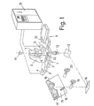
- Figur 1 eine schematische perspektivische Ansicht der wichtigsten Teile einer Projektionsformenschleifmaschine;
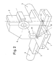
Figur 2 eine vergrößerte perspektivische Teilansicht der in Figur 1 dargestellten Projektionsformenschleifmaschine;Figur 3 vier Möglichkeiten einer in den Projektionsstrahlengang einführbaren Platte zur exakten Anzeige der Stellung des Schleifscheibenträgers undFigur 4 eine schematische Darstellung des Projektionsschirmes mit einer Sollformlinie und dem Bild des Markierungselements.
- Figure 1 is a schematic perspective view of the most important parts of a projection shape grinding machine;
- Figure 2 is an enlarged partial perspective view of the projection shape grinding machine shown in Figure 1;
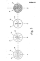
- 3 shows four possibilities of a plate which can be inserted into the projection beam path for the exact display of the position of the grinding wheel carrier and
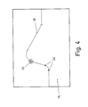
- Figure 4 is a schematic representation of the projection screen with a target shape line and the image of the marking element.
Auf einem Kreuztisch 1 einer Projektionsformenschleifmaschine mit zwei Schlitten 2 und 3, die mittels Stellmotoren 4 bzw. 5 senkrecht zueinander verschiebbar sind, ist auf dem oberen Schlitten 3 ein Träger 6 angeordnet, der einen in senkrechter Richtung verschieblichen Halter 7 trägt, an dem an einer horizontalen Welle eine Schleifscheibe 8 drehbar und motorisch angetrieben gelagert ist. (Figuren 1 und 2). Ein zweiter Kreuztisch 9 trägt das zu bearbeitende Werkstück 10, welches durch Verschiebung eines der beiden Kreuztische oder beider Kreuztische mit der Schleifscheibe in Eingriff bringbar ist.On a cross table 1 of a projection grinding machine with two
Die Eingriffsstelle wird mittels eines Projektionsstrahlenganges, der eine Lichtquelle 11, ein Projektionsobjektiv 12 sowie zwei Umlenkspiegel 13 und 14 umfaßt, auf einen Projektionsschirm 15 geworfen, auf dem das Bild 16 der Schleifscheibe und das Bild 17 des Werkstückes abgebildet sind. Auf dem Projektionsschirm ist entweder unmittelbar oder mittels eines aufgelegten durchsichtigen Trägers eine Sollformkurve 18 aufgezeichnet, die die Kontur markiert, welche das Werkstück nach der Bearbeitung aufweisen soll (Figur 4).The point of engagement is thrown onto a
Zur Bearbeitung des Werkstückes lassen sich die Schlitten 2 und 3 des Kreuztisches 1 entweder manuell über Handräder 19 und 2o oder über eine CNC-Steuerung 21 und die Stellmotoren 4 und 5 steuern.To machine the workpiece, the
An dem oberen Schlitten 3, der den Träger 6 aufnimmt, ist außerdem ein um eine senkrechte Achse verschwenkbarer Halter 22 gelagert, der an seinem freien Ende eine öffnung 23 aufweist, in die Platten 24 verschiedener Ausgestaltung eingelegt werden können (Figur 2). Mittels eines elektromotorischen Antriebs 25 läßt sich der Halter in eine erste, in Figur 2 ausgezogen dargestellte Stellung verschwenken, in welcher die öffnung mit der eingelegten Platte 24 im Projektionsstrahlengang angeordnet ist. In einer zweiten, in Figur 2 strichpunktiert dargestellten Stellung ist die öffnung 23 aus dem Projektionsstrahlengang ausgeschwenkt.On the
Die in die öffnung 23 einlegbaren Platten sind so ausgestaltet, daß die Position des von ihnen auf dem Projektionsschirm erzeugten Bildes 26 relativ zur Sollformkurve 18 möglichst genau feststellbar ist. Figur 3 zeigt einige mögliche Ausführungen der Platte 24. Die Platten A, B und C sind durchlässig für das Projektionslicht und weisen Linien auf, die den Mittelpunkt 27 der Platten deutlich machen. In der Platte A erfolgt dies durch zwei senkrecht zueinander stehende Linien 27 und durch den Mittelpunkt 28 konzentrisch umgebende Kreise. In dem Ausführungsbeispiel B schneiden sich vier jeweils um 45° gegeneinander gedrehte Linien 29 in einem Mittelpunkt 30. Im Ausführungsbeispiel C sind zwei senkrecht zueinander stehende Markierungslinienpaare 31 vorgesehen, die sich in einen Mittelpunkt 32 schneiden.The plates which can be inserted into the
Das Ausführungsbeispiel D stellt eine teilweise oder gar nicht für das Projektionslicht durchlässige Platte dar, die im Zentrum eine kleine öffnung 33 aufweist, deren Durchmesser beispielsweise 0,1 mm beträgt.The exemplary embodiment D represents a plate which is partially or not at all transparent to the projection light and which has a
Im eingeschwenkten Zustand werden die Linien 27, 29 und 31 der Platten gemäß Ausführungsbeispiel-A, B bzw. C als Bild 26 auf den Projektionsschirm geworfen, so daß man die Lage des jeweiligen Mittelpunkts 28, 30 bzw. 32 relativ zur Sollformlinie 18 genau bestimmen kann. Im Ausführungsbeispiel D erscheint das Bild der Öffnung 33 als heller Punkt in einem dunklen Umfeld und ist daher ebenfalls genau zu lokalisieren.In the swiveled-in state,
Zur Einspeicherung des Verlaufes der Sollformlinie wird die auf dem Projektionsschirm angeordnete Sollformlinie 18 an verschiedenen Stellen gekennzeichnet, so daß man ausgewählte Punkte 34 erhält. Der Kreuztisch 1 wird mittels der Handräder 19 und 20 so eingestellt, daß das Bild 26 des Markierungselements (Platte 24) mit seinem Mittelpunkt exakt auf dem Anfang der Sollformkurve liegt. Die entsprechende Position der beiden Schlitten 2 und 3 wird daraufhin abgespeichert. In gleicher Weise wird anschliessend das Zentrum des Bildes 26 durch Betätigung der Handräder 19 und 2o mit weiteren ausgewählten Punkten 34 zur Deckung gebracht, wobei jedes Mal die Koordinaten der Schlittenpositionen des Kreuztisches 1 gespeichert werden.In order to store the course of the target shape line, the
Als ausgewählte Punkte können beispielsweise die Enden geradliniger oder kreisförmig gebogener Linien dienen oder Knickstellen zwischen zwei geradlinigen Bereichen. Sobald der Steuerung die Lage dieser ausgewählten Punkte bekannt ist, kann sie aufgrund eines vorher eingegebenen Programms den exakten Linienverlauf zwischen den ausgewählten Punkten berechnen.The ends of straight or circular curved lines or kinks between two straight areas can serve as selected points, for example. As soon as the position of these selected points is known to the control, it can calculate the exact line course between the selected points based on a previously entered program.
Gemäß dieser Berechnung bewegt dann die Steuerung 21 die Schlitten 2 und 3 des Kreuztisches 1 und damit die Schleifscheibe 8, so daß eine entsprechende Kontur in das auf dem Kreuztisch 9 festgehaltene Werkstück 10 eingeschliffen wird.According to this calculation, the
Die Genauigkeit der Bestimmung der Koordinaten der ausgewählten Punkte ist bei diesem Verfahren außerordentlich hoch, da das Markierungselement durch den Projektionsstrahlengang stark vergrößert ist. Weiterhin ist das Verfahren für das Bedienungspersonal leicht und in kurzer Zeit durchzuführen, denn der Kreuztisch 1 wird mittels der Handräder 19 und 2o in der gleichen Weise verfahren, wie dies beim manuellen Schleifen von Werkstücken der Fall ist.The accuracy of the determination of the coordinates of the selected points is extremely high in this method, since the marking element is greatly enlarged by the projection beam path. Furthermore, the method for the operating personnel is easy and can be carried out in a short time, because the cross table 1 is moved by means of the
Insbesondere das Ausführungsbeispiel D der in Figur 3 dargestellten Platte 24 mit dem zentralen Loch eignet sich besonders gut zu einer automatischen Verschiebung der Schlitten 2 und 3 des Kreuztisches 1 bei der Speicherung der den ausgewählten Punkten entsprechenden Daten. Die Position des Bildes 26 kann nämlich aufgrund der Ausgestaltung der Platte mit einer sehr kleinen zentralen öffnung leicht mittels einer Photozelle abgetastet werden, welche anstelle der Handräder die'Verschiebung der Schlitten 2 und 3 des Kreuztisches 1 übernimmt, bis das Bild der beleuchteten zentralen öffnung 33 mit dem ausgewählten Punkt 34 übereinstimmt, der - wie erwähnt - durch Einstechen in die Sollkurve erzeugt werden kann, so daß auch dieser Punkt heller ist als die anliegenden Bereiche der Sollformkurve. Dabei ist es vorteilhaft, wenn der Durchmesser des Bildes der öffnung 33 der Strichbreite der Sollformlinie entspricht.In particular, the embodiment D of the
Claims (7)
Applications Claiming Priority (2)
| Application Number | Priority Date | Filing Date | Title |
|---|---|---|---|
| DE3136241A DE3136241C2 (en) | 1981-09-12 | 1981-09-12 | Use of a probe element and probe element that can be moved with the grinding wheel of an NC repetition-controlled projection shape grinding machine for this use |
| DE3136241 | 1981-09-12 |
Publications (3)
| Publication Number | Publication Date |
|---|---|
| EP0074484A2 true EP0074484A2 (en) | 1983-03-23 |
| EP0074484A3 EP0074484A3 (en) | 1983-06-01 |
| EP0074484B1 EP0074484B1 (en) | 1986-02-19 |
Family
ID=6141501
Family Applications (1)
| Application Number | Title | Priority Date | Filing Date |
|---|---|---|---|
| EP82106938A Expired EP0074484B1 (en) | 1981-09-12 | 1982-07-31 | Method and device for storing selected points of a nominal-shape line in a projection form grinding machine |
Country Status (4)
| Country | Link |
|---|---|
| US (1) | US4489522A (en) |
| EP (1) | EP0074484B1 (en) |
| JP (1) | JPH0664487B2 (en) |
| DE (2) | DE3136241C2 (en) |
Cited By (1)
| Publication number | Priority date | Publication date | Assignee | Title |
|---|---|---|---|---|
| EP0366053A2 (en) * | 1988-10-28 | 1990-05-02 | Michael Weinig Aktiengesellschaft | Device for producing a profile template |
Families Citing this family (14)
| Publication number | Priority date | Publication date | Assignee | Title |
|---|---|---|---|---|
| US4570385A (en) * | 1983-06-27 | 1986-02-18 | Fox Grinders, Inc. | Computer controlled workpiece finishing apparatus |
| DE3327117C2 (en) * | 1983-07-27 | 1986-02-13 | Dr. Johannes Heidenhain Gmbh, 8225 Traunreut | Method for the two-dimensional representation of three-dimensional structures |
| JPH0696220B2 (en) * | 1983-11-01 | 1994-11-30 | ワシノ機械株式会社 | Grinding method in optical copying grinding machine |
| JPH0641091B2 (en) * | 1983-11-10 | 1994-06-01 | ワシノ機械株式会社 | Grinding machine |
| US4630214A (en) * | 1984-04-13 | 1986-12-16 | Moore Special Tool Co., Ltd. | Jig grinder with automatic reciprocation and outfeed control |
| JPS60263211A (en) * | 1984-06-11 | 1985-12-26 | Toyoda Mach Works Ltd | Data input device of interactive numerically controlled machine tool |
| DE3521003A1 (en) * | 1985-06-12 | 1986-12-18 | Wilhelm 8372 Zwiesel König | Apparatus for grinding glass |
| US4791575A (en) * | 1986-10-31 | 1988-12-13 | The Pratt & Whitney Company, Inc. | Method for generating axis control data for use in controlling a grinding machine and the like and system therefor |
| JPS63305408A (en) * | 1987-06-08 | 1988-12-13 | Computer Apurikeeshiyonzu:Kk | Working method for deformed product |
| JPS641847U (en) * | 1987-06-24 | 1989-01-09 | ||
| JPH0818242B2 (en) * | 1989-03-14 | 1996-02-28 | 株式会社長瀬鉄工所 | Sander |
| DE10154766B4 (en) * | 2001-11-09 | 2007-01-25 | Profiltec Gmbh | Machine tool for producing a profile on a workpiece |
| EP1747846A1 (en) * | 2005-07-25 | 2007-01-31 | Rollomatic S.A. | Method and machine for the measurement of a cutting edge to be grinded |
| US20130331003A1 (en) * | 2012-05-17 | 2013-12-12 | Nils Eric Simonsen | Systems and methods for machine polishing a pattern onto metal using abrasive disks |
Citations (6)
| Publication number | Priority date | Publication date | Assignee | Title |
|---|---|---|---|---|
| CH146627A (en) * | 1930-02-11 | 1931-04-30 | Genevoise Instr Physique | Machine tool. |
| DE1213288B (en) * | 1956-12-21 | 1966-03-24 | Alfred Kolb Dipl Ing | Interpreting device |
| CH489331A (en) * | 1968-07-26 | 1970-04-30 | Kolb Alfred | Automatic projection form grinding machine |
| FR2295472A1 (en) * | 1974-12-20 | 1976-07-16 | Fiat Spa | AUTOMATIC MACHINE |
| FR2372678A1 (en) * | 1976-12-01 | 1978-06-30 | Kolb Alfred | AUTOMATICALLY CONTROLLED SHAPE GRINDING MACHINE |
| DE2934658A1 (en) * | 1979-06-28 | 1981-01-15 | Willemin Machines Sa | METHOD FOR CREATING AN ELECTRONIC PROGRAM TO BE USED IN A MACHINE TOOL |
Family Cites Families (9)
| Publication number | Priority date | Publication date | Assignee | Title |
|---|---|---|---|---|
| US2145116A (en) * | 1937-06-29 | 1939-01-24 | Darnley E Howard | Optical apparatus for indicating the position of a tool |
| US2378401A (en) * | 1942-05-13 | 1945-06-19 | Irvine C Gardner | Optical instrument and method of making same |
| US2553099A (en) * | 1946-03-30 | 1951-05-15 | American Optical Corp | Pantographic sighting apparatus for forming machines |
| US2957389A (en) * | 1957-01-14 | 1960-10-25 | Moore Frances Pauline | Optical pointer |
| DE1577349B2 (en) * | 1966-01-03 | 1972-09-28 | Hommelwerke Gmbh, 6800 Mannheim | OPTICAL PROJECTION FORM GRINDING MACHINE |
| US3629558A (en) * | 1969-09-12 | 1971-12-21 | Bendix Corp | Method for preparing control tapes |
| CH542020A (en) * | 1971-01-21 | 1973-09-30 | Albert Walser Praez Smechanik | Method for aligning the circular cylindrical surface part of a workpiece relative to the cylindrical machining tool of a machine tool and optical system for carrying out the method |
| JPS50145783A (en) * | 1974-05-17 | 1975-11-22 | ||
| JPS5274185A (en) * | 1975-12-16 | 1977-06-21 | Toshiba Mach Co Ltd | Program-driven contour processing machines |
-
1981
- 1981-09-12 DE DE3136241A patent/DE3136241C2/en not_active Expired
-
1982
- 1982-07-31 EP EP82106938A patent/EP0074484B1/en not_active Expired
- 1982-07-31 DE DE8282106938T patent/DE3269175D1/en not_active Expired
- 1982-09-07 JP JP57154751A patent/JPH0664487B2/en not_active Expired - Lifetime
- 1982-09-09 US US06/416,529 patent/US4489522A/en not_active Expired - Lifetime
Patent Citations (6)
| Publication number | Priority date | Publication date | Assignee | Title |
|---|---|---|---|---|
| CH146627A (en) * | 1930-02-11 | 1931-04-30 | Genevoise Instr Physique | Machine tool. |
| DE1213288B (en) * | 1956-12-21 | 1966-03-24 | Alfred Kolb Dipl Ing | Interpreting device |
| CH489331A (en) * | 1968-07-26 | 1970-04-30 | Kolb Alfred | Automatic projection form grinding machine |
| FR2295472A1 (en) * | 1974-12-20 | 1976-07-16 | Fiat Spa | AUTOMATIC MACHINE |
| FR2372678A1 (en) * | 1976-12-01 | 1978-06-30 | Kolb Alfred | AUTOMATICALLY CONTROLLED SHAPE GRINDING MACHINE |
| DE2934658A1 (en) * | 1979-06-28 | 1981-01-15 | Willemin Machines Sa | METHOD FOR CREATING AN ELECTRONIC PROGRAM TO BE USED IN A MACHINE TOOL |
Cited By (2)
| Publication number | Priority date | Publication date | Assignee | Title |
|---|---|---|---|---|
| EP0366053A2 (en) * | 1988-10-28 | 1990-05-02 | Michael Weinig Aktiengesellschaft | Device for producing a profile template |
| EP0366053A3 (en) * | 1988-10-28 | 1991-03-06 | Michael Weinig Aktiengesellschaft | Device for producing a profile template |
Also Published As
| Publication number | Publication date |
|---|---|
| JPH0664487B2 (en) | 1994-08-22 |
| US4489522A (en) | 1984-12-25 |
| DE3136241A1 (en) | 1983-03-31 |
| JPS58149510A (en) | 1983-09-05 |
| EP0074484A3 (en) | 1983-06-01 |
| EP0074484B1 (en) | 1986-02-19 |
| DE3136241C2 (en) | 1984-10-31 |
| DE3269175D1 (en) | 1986-03-27 |
Similar Documents
| Publication | Publication Date | Title |
|---|---|---|
| EP0074484B1 (en) | Method and device for storing selected points of a nominal-shape line in a projection form grinding machine | |
| EP0332864B1 (en) | Process for microinjection into living cells and apparatus therefor | |
| DE2654404C2 (en) | Transparent drawing to be placed on the screen of a numerically controllable projection shape grinding machine | |
| DE2725959C3 (en) | Electron beam processing equipment | |
| DE19736192C2 (en) | Irradiation system with several radiation sources aligned to a center | |
| DE3211174C2 (en) | Computerized drawing machine | |
| DE3444580C2 (en) | Device for examining the eyes | |
| DE2812637C3 (en) | Arrangement for the automatic insertion of a floppy disk into a floppy disk drive | |
| EP0011238A1 (en) | Measuring and data recording machine for a numerical controlled X-Y-contouring cutting machine for glass sheets and its use | |
| DE4013836A1 (en) | METHOD FOR CUTTING OUT A CUT | |
| DE3639740A1 (en) | METHOD FOR SCRAPING OUTLINES IN AN IMAGE CARRIER OR MOVIE | |
| DE19851411A1 (en) | Position measurement method for milling or drilling tool, using contactless measuring devices cooperating with rotary machining tool in its machining position | |
| EP0248184A2 (en) | Metal-working apparatus with a tool support movable in three mutually perpendicular directions | |
| EP0479976A1 (en) | Exact cutting to size in relation to a pattern repeat | |
| DE3644925C2 (en) | ||
| DE2942082A1 (en) | METHOD FOR SCANNING A PART OF AN IMAGE OUTLINE | |
| EP0366053A2 (en) | Device for producing a profile template | |
| DE19705883A1 (en) | Method and device for copying three-dimensional objects | |
| EP0002063B1 (en) | Apparatus for projecting light spots on a printed circuit on which components are to be mounted | |
| DE2420981C3 (en) | Coordinate measuring machine | |
| EP3758884B1 (en) | Device and method for machining a workpiece by means of a laser beam | |
| CH631375A5 (en) | Process and apparatus for profiling a grinding wheel | |
| DE4233010A1 (en) | Trolley for setting and exchanging cutter beam of slitting machine - has traversing slide with measuring scale so that cutter beam can be held in zero position and cutter holders pushed along beam and set in desired position away from machine | |
| EP0220528A1 (en) | Device for displaying positions on a map | |
| DE2357137C3 (en) | Coordinate reader for reading after registering the coordinates of points on a drawing sheet |
Legal Events
| Date | Code | Title | Description |
|---|---|---|---|
| PUAI | Public reference made under article 153(3) epc to a published international application that has entered the european phase |
Free format text: ORIGINAL CODE: 0009012 |
|
| AK | Designated contracting states |
Designated state(s): CH DE FR GB IT LI |
|
| PUAL | Search report despatched |
Free format text: ORIGINAL CODE: 0009013 |
|
| AK | Designated contracting states |
Designated state(s): CH DE FR GB IT LI |
|
| 17P | Request for examination filed |
Effective date: 19830630 |
|
| ITF | It: translation for a ep patent filed |
Owner name: BARZANO' E ZANARDO MILANO S.P.A. |
|
| GRAA | (expected) grant |
Free format text: ORIGINAL CODE: 0009210 |
|
| RAP1 | Party data changed (applicant data changed or rights of an application transferred) |
Owner name: WERKZEUGMASCHINENBAU PRAEZISIONS-TECHNIK GMBH |
|
| AK | Designated contracting states |
Kind code of ref document: B1 Designated state(s): CH DE FR GB IT LI |
|
| ET | Fr: translation filed | ||
| REF | Corresponds to: |
Ref document number: 3269175 Country of ref document: DE Date of ref document: 19860327 |
|
| PLBE | No opposition filed within time limit |
Free format text: ORIGINAL CODE: 0009261 |
|
| STAA | Information on the status of an ep patent application or granted ep patent |
Free format text: STATUS: NO OPPOSITION FILED WITHIN TIME LIMIT |
|
| 26N | No opposition filed | ||
| ITTA | It: last paid annual fee | ||
| PGFP | Annual fee paid to national office [announced via postgrant information from national office to epo] |
Ref country code: FR Payment date: 19920611 Year of fee payment: 11 |
|
| PGFP | Annual fee paid to national office [announced via postgrant information from national office to epo] |
Ref country code: GB Payment date: 19920717 Year of fee payment: 11 |
|
| PG25 | Lapsed in a contracting state [announced via postgrant information from national office to epo] |
Ref country code: GB Effective date: 19930731 |
|
| PGFP | Annual fee paid to national office [announced via postgrant information from national office to epo] |
Ref country code: CH Payment date: 19930802 Year of fee payment: 12 |
|
| PGFP | Annual fee paid to national office [announced via postgrant information from national office to epo] |
Ref country code: DE Payment date: 19930818 Year of fee payment: 12 |
|
| GBPC | Gb: european patent ceased through non-payment of renewal fee |
Effective date: 19930731 |
|
| PG25 | Lapsed in a contracting state [announced via postgrant information from national office to epo] |
Ref country code: FR Effective date: 19940331 |
|
| REG | Reference to a national code |
Ref country code: FR Ref legal event code: ST |
|
| PG25 | Lapsed in a contracting state [announced via postgrant information from national office to epo] |
Ref country code: LI Effective date: 19940731 Ref country code: CH Effective date: 19940731 |
|
| REG | Reference to a national code |
Ref country code: CH Ref legal event code: PL |
|
| PG25 | Lapsed in a contracting state [announced via postgrant information from national office to epo] |
Ref country code: DE Effective date: 19950401 |