EP0073298B1 - Unterform zum Formen von Betondachsteinen im Strangpressverfahren - Google Patents
Unterform zum Formen von Betondachsteinen im Strangpressverfahren Download PDFInfo
- Publication number
- EP0073298B1 EP0073298B1 EP82104498A EP82104498A EP0073298B1 EP 0073298 B1 EP0073298 B1 EP 0073298B1 EP 82104498 A EP82104498 A EP 82104498A EP 82104498 A EP82104498 A EP 82104498A EP 0073298 B1 EP0073298 B1 EP 0073298B1
- Authority
- EP
- European Patent Office
- Prior art keywords
- upper shell
- shell
- lower shell
- pallet
- edge
- Prior art date
- Legal status (The legal status is an assumption and is not a legal conclusion. Google has not performed a legal analysis and makes no representation as to the accuracy of the status listed.)
- Expired
Links
- 238000001125 extrusion Methods 0.000 title claims abstract description 5
- 238000000034 method Methods 0.000 title claims abstract description 4
- 229910000831 Steel Inorganic materials 0.000 claims abstract description 6
- 239000010959 steel Substances 0.000 claims abstract description 6
- 238000003466 welding Methods 0.000 claims abstract description 6
- 229920005830 Polyurethane Foam Polymers 0.000 claims description 3
- 239000011496 polyurethane foam Substances 0.000 claims description 3
- 239000000463 material Substances 0.000 claims description 2
- 239000011796 hollow space material Substances 0.000 claims 1
- 239000011810 insulating material Substances 0.000 claims 1
- 239000011324 bead Substances 0.000 description 17
- 238000004519 manufacturing process Methods 0.000 description 6
- 239000011248 coating agent Substances 0.000 description 3
- 238000000576 coating method Methods 0.000 description 3
- 238000005056 compaction Methods 0.000 description 3
- XLYOFNOQVPJJNP-UHFFFAOYSA-N water Substances O XLYOFNOQVPJJNP-UHFFFAOYSA-N 0.000 description 3
- 238000005452 bending Methods 0.000 description 2
- 239000011449 brick Substances 0.000 description 2
- 150000001875 compounds Chemical class 0.000 description 2
- 230000006835 compression Effects 0.000 description 2
- 238000007906 compression Methods 0.000 description 2
- 239000002184 metal Substances 0.000 description 2
- 210000001331 nose Anatomy 0.000 description 2
- -1 Polyurethane foam Chemical class 0.000 description 1
- 229910000746 Structural steel Inorganic materials 0.000 description 1
- 230000015572 biosynthetic process Effects 0.000 description 1
- 238000005260 corrosion Methods 0.000 description 1
- 230000007797 corrosion Effects 0.000 description 1
- 238000009413 insulation Methods 0.000 description 1
Images


Classifications
-
- B—PERFORMING OPERATIONS; TRANSPORTING
- B28—WORKING CEMENT, CLAY, OR STONE
- B28B—SHAPING CLAY OR OTHER CERAMIC COMPOSITIONS; SHAPING SLAG; SHAPING MIXTURES CONTAINING CEMENTITIOUS MATERIAL, e.g. PLASTER
- B28B7/00—Moulds; Cores; Mandrels
- B28B7/0029—Moulds or moulding surfaces not covered by B28B7/0058 - B28B7/36 and B28B7/40 - B28B7/465, e.g. moulds assembled from several parts
- B28B7/0055—Mould pallets; Mould panels
-
- B—PERFORMING OPERATIONS; TRANSPORTING
- B28—WORKING CEMENT, CLAY, OR STONE
- B28B—SHAPING CLAY OR OTHER CERAMIC COMPOSITIONS; SHAPING SLAG; SHAPING MIXTURES CONTAINING CEMENTITIOUS MATERIAL, e.g. PLASTER
- B28B7/00—Moulds; Cores; Mandrels
- B28B7/34—Moulds, cores, or mandrels of special material, e.g. destructible materials
Definitions
- the invention relates to a lower mold for forming concrete roof tiles in the extrusion process, which is produced from an upper shell and a lower shell from pressed steel sheet by welding these shells and in which the upper shell has a central and longitudinal bead.
- Known subforms of this type are fed in a continuous line from a conveyor belt to a coating and compaction system in which a fresh concrete layer is applied to the subforms. This layer is then mechanically compressed and shaped into shaped articles.
- a lower mold according to the preamble of claim 1 is known (AT-B-180 886), in which the lower shell has two channel-like depressions which are continuous in length and are located below flat areas arranged on both sides of the central bead in the upper shell. At the transverse edges of the flat areas, sheet metal tabs corresponding to the cross-sectional shape of the depressions are cut out and bent downward in order to form end walls of depressions for the production of brick noses. Together with the end plates welded on the end face between the troughs, the end walls are also intended to stiffen the lower mold in the transverse direction.
- a lower mold (GB-A-663 310), which consists of two shells joined together by welding and in which the upper shell has pressed-in portions on one side edge to form brick lugs, while in the lower shell, frusto-conical extrusions are provided at regular longitudinal and transverse distances are provided, which serve to stiffen the lower mold.
- a lower mold can withstand the compressive forces acting on the mold from above to some extent, but further measures are required for effective stiffening against bending in the longitudinal and transverse directions.
- the invention has for its object to provide a particularly light and stable bottom mold with simple means and in a rational manner, which withstands both the high compression forces acting on the form from above and an effective stiffening against bending in the longitudinal direction - Has and transverse direction and is also suitable for the production of concrete roof tiles that have a central brim arch and a water fold on one longitudinal edge and a cover fold on the other longitudinal edge.
- this object is achieved on the basis of a lower mold in accordance with the preamble of claim 1 in that the upper shell has an edge bead on both longitudinal sides and the lower shell has at least two beads which run in the transverse direction and extend in height up to the upper shell, with the upper shell are connected by spot welding to flat areas located between the bead and the edge beads.
- the material thickness of the upper shell and the lower shell is 0.85 to 1.5 mm in each case.
- the lower shell has a central and longitudinal bead which is at its head end by an insert part from FIG. 3 up to 6 mm thick steel sheet is closed, which is welded to the upper shell and the lower shell. The forces exerted on it by the feed cams can be safely absorbed by this insert.
- an insulating compound e.g. Polyurethane foam is filled, so this still improves the dimensional stability of the lower mold and noise insulation in roof tile production as well as corrosion protection of the cavities.
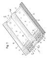
- the lower mold shown in Fig. 1 with a view of the top is used to manufacture known concrete roof tiles.
- the central brim arch of the roof tiles is formed by means of a bead 30 running in the middle of the lower mold and in the longitudinal direction.
- Flat regions 31, with which water guiding surfaces are formed in the roof tile, extend on both sides of the bead.
- Upper transverse recesses 32 are used for the production of nose slats and a number of lower transverse recesses 33, 34, 35 are used for the production of foot-side ribs.
- On the right longitudinal edge 36 of the lower mold is by means of a located on an edge bead 37 Rib and groove formation of the roof rebate shaped.
- the water rebate of the roof tile is generated over an edge bead 39.
- the lower mold moves with the fresh concrete layer lying on it under a correspondingly profiled roller and a smoother in the direction of arrow I.
- the lower mold has on its underside three transverse beads 40 with a trapezoidal cross section, which serve to stiffen the lower mold.
- planar elevations 41, 42, 43 provided in the flat areas and step-like offset edge surfaces 44, 45 provided on the longitudinal edges 36, 38, the lower mold rests on sliding guides when passing through the coating and compression system.
- the lower mold consists of an upper shell 10 and a lower shell 20.
- the shells are made from unalloyed structural steel sheets, which have a thickness of approximately 1.25 mm, by deep drawing.
- the upper shell 10 and the lower shell 20 are in the region of the lower end of the bead 30 which runs centrally and in the longitudinal direction in the upper shell and the lower and upper ends of the edge beads 37, 39 and on their longitudinal edges 36, 38 with adjacent edge strips 11, 21 and 12, 22, which are designed as flanged edges, while in the region of the lower and upper edge-side closures of the depressions 32, 33, offset edge strips 13, 23 abut one another.
- the upper shell is connected to the lower shell at the longitudinal edges 36, 38 by weld seams 46, as is indicated in FIG. 5 and in FIG. 1.
- the lower shell also lies against the upper shell 10 in the region of the beads 40 running in the transverse direction in the lower shell 20. In this area, the shells are connected to one another by four welding points 47 per sikke, as is indicated in FIG. 5 in addition to FIG. 5.
- an insert part 49 is provided at the upper end of a bead 48 running centrally and in the longitudinal direction in the lower shell 20, which consists of approximately 5 mm thick steel sheet and that with the upper shell 10 and The lower shell 20 is welded in order to be able to absorb the forces exerted by feed cams.
- the cavity 50 remaining between the upper shell and the lower shell 20 is covered with an insulating compound, e.g. Polyurethane foam, filled out.
- an insulating compound e.g. Polyurethane foam
Landscapes
- Engineering & Computer Science (AREA)
- Manufacturing & Machinery (AREA)
- Chemical & Material Sciences (AREA)
- Ceramic Engineering (AREA)
- Mechanical Engineering (AREA)
- Press-Shaping Or Shaping Using Conveyers (AREA)
- Curing Cements, Concrete, And Artificial Stone (AREA)
- On-Site Construction Work That Accompanies The Preparation And Application Of Concrete (AREA)
- Pharmaceuticals Containing Other Organic And Inorganic Compounds (AREA)
- Moulds, Cores, Or Mandrels (AREA)
- Manufacturing Of Tubular Articles Or Embedded Moulded Articles (AREA)
- Medicinal Preparation (AREA)
- Roof Covering Using Slabs Or Stiff Sheets (AREA)
- Devices For Post-Treatments, Processing, Supply, Discharge, And Other Processes (AREA)
Description
- Die Erfindung betrifft eine Unterform zum Formen von Betondachsteinen im Strangpressverfahren, die aus einer Oberschale und einer Unterschale aus gepresstem Stahlblech durch Verschweissen dieser Schalen hergestellt ist und bei der die Oberschale einen mittig und in Längsrichtung verlaufenden Wulst aufweist.
- Bekannte Unterformen dieser Art werden in einem durchgehenden Strang von einem Förderband einer Beschichtungs- und Verdichtungsanlage zugeführt, in der eine Frischbetonschicht auf die Unterformen aufgebracht wird. Diese Schicht wird anschliessend zu Formlingen mechanisch verdichtet und profiliert.
- Es ist eine Unterform gemäss dem Oberbegriff des Patentanspruchs 1 bekannt (AT-B-180 886), bei der die Unterschale zwei der Länge nach durchgehende rinnenartige Vertiefungen aufweist, die sich unterhalb von in der Oberschale beidseitig des mittig verlaufenden Wulstes angeordneten Flachbereichen befinden. An den Querkanten der Flachbereiche sind der Querschnittsform der Vertiefungen entsprechende Blechlappen ausgeschnitten und nach abwärts gebogen, um stirnseitige Abschlusswände von Mulden zur Herstellung von Ziegelnasen zu bilden. Zusammen mit stirnseitig zwischen den Mulden angeschweissten Abschlussplatten sollen die Abschlusswände ausserdem die Unterform in Querrichtung versteifen. Da jedoch unter den in der Oberschale in Längsrichtung verlaufenden Wülsten und über den in der Unterschale vorgesehenen rinnenartigen Vertiefungen zwischen den jeweiligen stirnseitigen Abschlusswänden durchgehende Hohlräume bestehen, kann eine solche Unterform, sofern sie nur aus dünnen Blechen hergestellt ist, in diesen Bereichen den von oben einwirkenden hohen Verdichtungskräften nicht standhalten.
- Ferner ist eine Unterform bekannt (GB-A-663 310), die aus zwei durch Schweissen miteinander verbundenen Schalen besteht und bei der die Oberschale an einer Seitenkante Einpressungen zur Formung von Ziegelnasen aufweist, während in der Unterschale in regelmässigen Längs-und Querabständen kegelstumpfförmige Auspressungen vorgesehen sind, die der Versteifung der Unterform dienen. Eine derartige Unterform kann zwar den von oben auf die Form einwirkenden Verdichtungskräften einigermassen standhalten, für eine wirksame Versteifung gegenüber Verbiegen in Längs- und Querrichtung sind jedoch weitere Massnahmen erforderlich.
- Ausgehend von diesem Stand der Technik liegt der Erfindung die Aufgabe zugrunde, mit einfachen Mitteln und in rationeller Weise eine besonders leichte und stabile Unterform zu schaffen, die sowohl den von oben auf die Form einwirkenden hohen Verdichtungskräften standhält als auch eine wirksame Versteifung gegenüber Verbiegen in Längs- und Querrichtung aufweist und die auch zur Herstellung von Betondachsteinen geeignet ist, die einen Mittelkrempenbogen sowie an dem einen Längsrand einen Wasserfalz und an dem anderen Längsrand einen Deckfalz aufweisen.
- Erfindungsgemäss wird diese Aufgabe ausgehend von einer Unterform gemäss dem Oberbegriff des Anspruchs 1 dadurch gelöst, dass die Oberschale an beiden Längsseiten je einen Randwulst und die Unterschale zumindest zwei in Querrichtung verlaufende und in der Höhe bis zur Oberschale sich erstreckende Sicken aufweist, die mit der Oberschale an zwischen dem Wulst und den Randwülsten befindlichen Flachbereichen durch Punktschweissen verbunden sind.
- Wie festgestellt wurde, ist es für die Stabilität derartiger Unterformen ausreichend, wenn die Materialdicke der Oberschale und der Unterschale jeweils 0,85 bis 1,5 mm beträgt.
- Für derartige, einen durchgehenden Strang bildende Unterformen, die mittels von unten angreifender Vorschubnocken durch eine Beschichtungs- und Verdichtungsanlage gefördert werden, ist weiter vorgesehen, dass die Unterschale eine mittig und in Längsrichtung verlaufende Sicke aufweist, die an ihrem kopfseitigen Ende durch ein Einsatzteil aus 3 bis 6 mm starkem Stahlblech geschlossen ist, das mit der Oberschale und der Unterschale verschweisst ist. Von diesem Einsatzteil können die daran angreifenden von den Vorschubnocken ausgeübten Kräfte sicher aufgenommen werden.
- Wenn dann noch der zwischen der Ober- und Unterschale verbleibende Hohlraum mit einer Dämmasse, z.B. Polyurethanschaum, ausgefüllt ist, so wird hierdurch noch eine Verbesserung der Formstabilität der Unterform und eine Geräuschdämmung bei der Dachsteinherstellung wie auch ein Korrosionsschutz der Hohlräume erzielt.
- Ein Ausführungsbeispiel der Erfindung wird nachstehend anhand der beigefügten Zeichnungen näher erläutert. Es zeigen:
- Fig. 1 eine perspektivische Darstellung der Unterform gemäss der Erfindung mit Blick auf die Oberseite,
- Fig. 2 eine perspektivische Darstellung der Unterform nach Fig. 1 mit Blick auf die Unterseite,
- Fig. 3 einen Schnitt entsprechend der Linie 111-111 in Fig. 1 in vergrössertem Massstab,
- Fig.4 einen Schnitt entsprechend der Linie IV-IV in Fig. 1 in vergrössertem Massstab,
- Fig. 5 einen Schnitt entsprechend der Linie V-V in Fig. 2 in vergrössertem Massstab.
- Die in Fig. 1 mit Blick auf die Oberseite dargestellte Unterform dient der Herstellung von bekannten Betondachsteinen. Mittels eines in der Unterform mittig und in Längsrichtung verlaufenden Wulstes 30 wird der Mittelkrempenbogen der Dachsteine gebildet. Beidseitig vom Wulst erstrecken sich Flachbereiche 31, mit denen Wasserführungsflächen im Dachstein geformt werden. Obere in Querrichtung verlaufende Vertiefungen 32 dienen der Herstellung von mit Nasen versehenen Aufhängeleisten und eine Anzahl von unteren in Querrichtung verlaufender Vertiefungen 33, 34, 35 der Herstellung von fussseitigen Rippen. An dem rechten Längsrand 36 der Unterform wird mittels einer an einem Randwulst 37 befindlichen Rippen- und Nutenausbildung der Deckfalz des Dachsteins geformt. An dem gegenüberliegenden Längsrand 38 der Unterform wird über einem Randwulst 39 der Wasserfalz des Dachsteins erzeugt. Dabei bewegt sich die Unterform mit der auf ihr liegenden Frischbetonschicht unter einer entsprechend profilierten Walze und einem Glätter in Richtung des Pfeils I fort.
- Wie der Fig. 2 zu entnehmen ist, weist die Unterform an ihrer Unterseite drei in Querrichtung verlaufende Sicken 40 mit trapezförmigem Querschnitt auf, die der Versteifung der Unterform dienen. Mit in den ebenen Bereichen vorgesehenen flächigen Erhebungen 41, 42, 43 und an den Längsrändern 36, 38 vorgesehenen stufenförmig abgesetzten Randflächen 44, 45 liegt die Unterform beim Durchlaufen der Beschichtungs- und Verdichtungsanlage auf Gleitführungen auf.
- Wie Fig. 3 bis 5 entnommen werden kann, besteht die Unterform aus einer Oberschale 10 und einer Unterschale 20. Die Schalen sind aus unlegierten Baustahlblechen, die eine Dicke von etwa 1,25 mm aufweisen, durch Tiefziehen hergestellt. Die Oberschale 10 und die Unterschale 20 sind im Bereich des unteren Abschlusses des in der Oberschale mittig und in Längsrichtung verlaufenden Wulstes 30 und der unteren und oberen Abschlüsse der Randwülste 37, 39 sowie an ihren Längsrändern 36, 38 mit aneinanderliegenden Randstreifen 11, 21 bzw. 12, 22 versehen, die als Bördelränder ausgebildet sind, während im Bereich der unteren und oberen randseitigen Abschlüsse der Vertiefungen 32, 33 abgekröpfte Randstreifen 13, 23 aneinanderliegen. Die Oberschale ist mit der Unterschale an den Längsrändern 36, 38 durch Schweissnähte 46 verbunden, wie dies in Fig. 5 und in Fig. 1 angedeutet ist. Auch im Bereich der in der Unterschale 20 in Querrichtung verlaufenden Sicken 40 liegt die Unterschale an der Oberschale 10 an. In diesem Bereich sind die Schalen durch je vier Schweisspunkte 47 pro Sikke miteinander verbunden, wie dies ausser in Fig. 5 auch in Fig. 2 angedeutet ist.
- Fig. 2 und Fig. 3 kann entnommen werden, dass an dem oberen Ende einer in der Unterschale 20 mittig und in Längsrichtung verlaufenden Sicke 48 ein Einsatzteil 49 vorgesehen ist, das aus etwa 5 mm starkem Stahlblech besteht und das mit der Oberschale 10 und der Unterschale 20 verschweisst ist, um die von Vorschubnocken ausgeübten Kräfte aufnehmen zu können.
- Wie in den Fig. 3 bis 5 durch Punktlinien angedeutet ist, ist der zwischen der Oberschale und der Unterschale 20 verbleibende Hohlraum 50 mit einer Dämmasse, z.B. Polyurethanschaum, ausgefüllt.
Claims (4)
Priority Applications (1)
| Application Number | Priority Date | Filing Date | Title |
|---|---|---|---|
| AT82104498T ATE21225T1 (de) | 1981-08-22 | 1982-05-22 | Unterform zum formen von betondachsteinen im strangpressverfahren. |
Applications Claiming Priority (2)
| Application Number | Priority Date | Filing Date | Title |
|---|---|---|---|
| DE19813133290 DE3133290A1 (de) | 1981-08-22 | 1981-08-22 | Unterform fuer eine strangpresseinrichtung zur herstellung von betondachsteinen |
| DE3133290 | 1981-08-22 |
Publications (3)
| Publication Number | Publication Date |
|---|---|
| EP0073298A2 EP0073298A2 (de) | 1983-03-09 |
| EP0073298A3 EP0073298A3 (en) | 1983-08-24 |
| EP0073298B1 true EP0073298B1 (de) | 1986-08-06 |
Family
ID=6139908
Family Applications (1)
| Application Number | Title | Priority Date | Filing Date |
|---|---|---|---|
| EP82104498A Expired EP0073298B1 (de) | 1981-08-22 | 1982-05-22 | Unterform zum Formen von Betondachsteinen im Strangpressverfahren |
Country Status (5)
| Country | Link |
|---|---|
| EP (1) | EP0073298B1 (de) |
| AT (1) | ATE21225T1 (de) |
| DE (2) | DE3133290A1 (de) |
| DK (1) | DK154995C (de) |
| NO (1) | NO156321C (de) |
Families Citing this family (4)
| Publication number | Priority date | Publication date | Assignee | Title |
|---|---|---|---|---|
| DE4130560A1 (de) * | 1991-09-13 | 1993-03-18 | Rieter Werke Haendle | Pressform fuer eine dachziegelpresse |
| JP2620057B2 (ja) * | 1992-12-07 | 1997-06-11 | ヘー スー,クン | 建材連続成形装置 |
| DE69423909D1 (de) * | 1993-12-10 | 2000-05-11 | Marley Tile Ag Luzern Lucerne | Dachziegelsystem |
| GB2314356B (en) * | 1993-12-10 | 1998-02-18 | Marley Building Materials Ltd | Roof tiles |
Family Cites Families (3)
| Publication number | Priority date | Publication date | Assignee | Title |
|---|---|---|---|---|
| GB663310A (en) * | 1949-04-29 | 1951-12-19 | Marley Tile Co Ltd | Improvements in or relating to pallets for moulding tiles |
| AT180886B (de) * | 1952-06-03 | 1955-01-25 | Rudolf Czettel | Dachziegelformplatte zur Herstellung von Falzziegeln auf Maschinen mit endlosem Formenzug |
| DE2912080A1 (de) * | 1979-03-27 | 1980-10-16 | Upjohn Co | Verfahren und vorrichtung zum an mehreren stationen an ort und stelle erfolgenden ausschaeumen von gegenstaenden mit einer reaktionsfaehigen polymeren kunstharzmasse |
-
1981
- 1981-08-22 DE DE19813133290 patent/DE3133290A1/de not_active Withdrawn
-
1982
- 1982-05-22 EP EP82104498A patent/EP0073298B1/de not_active Expired
- 1982-05-22 DE DE8282104498T patent/DE3272444D1/de not_active Expired
- 1982-05-22 AT AT82104498T patent/ATE21225T1/de not_active IP Right Cessation
- 1982-05-27 NO NO821770A patent/NO156321C/no unknown
- 1982-05-28 DK DK243382A patent/DK154995C/da not_active IP Right Cessation
Also Published As
| Publication number | Publication date |
|---|---|
| ATE21225T1 (de) | 1986-08-15 |
| DK243382A (da) | 1983-02-23 |
| DK154995C (da) | 1989-05-29 |
| DK154995B (da) | 1989-01-23 |
| DE3272444D1 (en) | 1986-09-11 |
| EP0073298A2 (de) | 1983-03-09 |
| NO156321B (no) | 1987-05-25 |
| NO821770L (no) | 1983-02-23 |
| EP0073298A3 (en) | 1983-08-24 |
| DE3133290A1 (de) | 1983-03-03 |
| NO156321C (no) | 1987-09-02 |
Similar Documents
| Publication | Publication Date | Title |
|---|---|---|
| DE1509606A1 (de) | Fussbodenplatte | |
| DE2646633C2 (de) | Verbundstoffplatte | |
| DE2407753A1 (de) | Verfahren und vorrichtung zur herstellung von bauelementen sowie damit hergestellte elemente | |
| EP0073298A2 (de) | Unterform zum Formen von Betondachsteinen im Strangpressverfahren | |
| DE2021744A1 (de) | Verfahren zur Herstellung von isolierten Dachverschalungen sowie nach diesem Verfahren hergestellte Dachverschalung | |
| DE3103332C2 (de) | Firstentlüftung an Dächern | |
| DE2145628C3 (de) | ||
| EP2931987B1 (de) | Zarge einer entwässerungsrinne | |
| CH663244A5 (de) | Abstandshalter zur verwendung bei wandbauelementen. | |
| DE2734195C2 (de) | Wärmedämmplatte aus Schaumkunststoff für ein Unterdach | |
| DE3012346A1 (de) | Dacheindeckungsplatte | |
| DE7929663U1 (de) | Streifen zur rissinduzierung und abdichtung in beton | |
| DE3318608C2 (de) | ||
| DE3147651C2 (de) | Aus Betonfertigteilen bestehender Zellensilo | |
| DE2340309A1 (de) | Waermedaemmende innenverkleidung fuer dachflaechen mit dachsparren und dachlatten | |
| EP0036526A2 (de) | First- oder Gratabdeckung | |
| DE1759427C (de) | Verfahren zum Herstellen von Dichtungsstreifen aus Schaumkunst stoff auf Dacheindeckungsplatten | |
| EP1624125B1 (de) | Fertigteildachbaukasten | |
| DE1629460C3 (de) | ||
| EP0002817A2 (de) | Firstziegel | |
| EP0193522B1 (de) | Gegensickenverstärkte Schneefangnasen | |
| EP0887485B1 (de) | Gipsplattenelement für eine Wand/Decke-Unterkonstruktion | |
| EP0021240A1 (de) | Mauerstein | |
| DE2354191C3 (de) | Vorgefertigtes Dachbauelement zur Herstellung von Scheddächern | |
| EP1113119A2 (de) | Dachziegel |
Legal Events
| Date | Code | Title | Description |
|---|---|---|---|
| PUAI | Public reference made under article 153(3) epc to a published international application that has entered the european phase |
Free format text: ORIGINAL CODE: 0009012 |
|
| AK | Designated contracting states |
Designated state(s): AT BE DE FR IT LU NL SE |
|
| PUAL | Search report despatched |
Free format text: ORIGINAL CODE: 0009013 |
|
| AK | Designated contracting states |
Designated state(s): AT BE DE FR IT LU NL SE |
|
| 17P | Request for examination filed |
Effective date: 19830628 |
|
| GRAA | (expected) grant |
Free format text: ORIGINAL CODE: 0009210 |
|
| AK | Designated contracting states |
Kind code of ref document: B1 Designated state(s): AT BE DE FR IT LU NL SE |
|
| REF | Corresponds to: |
Ref document number: 21225 Country of ref document: AT Date of ref document: 19860815 Kind code of ref document: T |
|
| REF | Corresponds to: |
Ref document number: 3272444 Country of ref document: DE Date of ref document: 19860911 |
|
| ITF | It: translation for a ep patent filed | ||
| ET | Fr: translation filed | ||
| PLBE | No opposition filed within time limit |
Free format text: ORIGINAL CODE: 0009261 |
|
| STAA | Information on the status of an ep patent application or granted ep patent |
Free format text: STATUS: NO OPPOSITION FILED WITHIN TIME LIMIT |
|
| 26N | No opposition filed | ||
| ITTA | It: last paid annual fee | ||
| NLT1 | Nl: modifications of names registered in virtue of documents presented to the patent office pursuant to art. 16 a, paragraph 1 |
Owner name: BRAAS GMBH TE OBERURSEL, BONDSREPUBLIEK DUITSLAND. |
|
| REG | Reference to a national code |
Ref country code: FR Ref legal event code: CD Ref country code: FR Ref legal event code: CA |
|
| ITPR | It: changes in ownership of a european patent |
Owner name: CAMBIO RAGIONE SOCIALE;BRAAS GMBH |
|
| PGFP | Annual fee paid to national office [announced via postgrant information from national office to epo] |
Ref country code: SE Payment date: 19930512 Year of fee payment: 12 |
|
| PGFP | Annual fee paid to national office [announced via postgrant information from national office to epo] |
Ref country code: FR Payment date: 19930513 Year of fee payment: 12 |
|
| PGFP | Annual fee paid to national office [announced via postgrant information from national office to epo] |
Ref country code: BE Payment date: 19930517 Year of fee payment: 12 |
|
| PGFP | Annual fee paid to national office [announced via postgrant information from national office to epo] |
Ref country code: LU Payment date: 19930519 Year of fee payment: 12 Ref country code: AT Payment date: 19930519 Year of fee payment: 12 |
|
| PGFP | Annual fee paid to national office [announced via postgrant information from national office to epo] |
Ref country code: DE Payment date: 19930526 Year of fee payment: 12 |
|
| PGFP | Annual fee paid to national office [announced via postgrant information from national office to epo] |
Ref country code: NL Payment date: 19930531 Year of fee payment: 12 |
|
| EPTA | Lu: last paid annual fee | ||
| PG25 | Lapsed in a contracting state [announced via postgrant information from national office to epo] |
Ref country code: LU Free format text: LAPSE BECAUSE OF NON-PAYMENT OF DUE FEES Effective date: 19940522 Ref country code: AT Effective date: 19940522 |
|
| PG25 | Lapsed in a contracting state [announced via postgrant information from national office to epo] |
Ref country code: SE Effective date: 19940523 |
|
| PG25 | Lapsed in a contracting state [announced via postgrant information from national office to epo] |
Ref country code: BE Effective date: 19940531 |
|
| BERE | Be: lapsed |
Owner name: BRAAS & CO. G.M.B.H. Effective date: 19940531 |
|
| PG25 | Lapsed in a contracting state [announced via postgrant information from national office to epo] |
Ref country code: NL Effective date: 19941201 |
|
| NLV4 | Nl: lapsed or anulled due to non-payment of the annual fee | ||
| EUG | Se: european patent has lapsed |
Ref document number: 82104498.9 Effective date: 19941210 |
|
| PG25 | Lapsed in a contracting state [announced via postgrant information from national office to epo] |
Ref country code: FR Effective date: 19950131 |
|
| PG25 | Lapsed in a contracting state [announced via postgrant information from national office to epo] |
Ref country code: DE Effective date: 19950201 |
|
| EUG | Se: european patent has lapsed |
Ref document number: 82104498.9 |
|
| REG | Reference to a national code |
Ref country code: FR Ref legal event code: ST |