EP0067339B1 - Verfahren und Anordnung zur Störungserkennung in Gefahren-, insbesondere Brandmeldeanlagen - Google Patents
Verfahren und Anordnung zur Störungserkennung in Gefahren-, insbesondere Brandmeldeanlagen Download PDFInfo
- Publication number
- EP0067339B1 EP0067339B1 EP82104677A EP82104677A EP0067339B1 EP 0067339 B1 EP0067339 B1 EP 0067339B1 EP 82104677 A EP82104677 A EP 82104677A EP 82104677 A EP82104677 A EP 82104677A EP 0067339 B1 EP0067339 B1 EP 0067339B1
- Authority
- EP
- European Patent Office
- Prior art keywords
- alarm
- value
- measured values
- comparator
- input
- Prior art date
- Legal status (The legal status is an assumption and is not a legal conclusion. Google has not performed a legal analysis and makes no representation as to the accuracy of the status listed.)
- Expired
Links
- 238000000034 method Methods 0.000 title claims abstract description 14
- 238000001514 detection method Methods 0.000 title description 7
- 230000011664 signaling Effects 0.000 title description 4
- 230000007257 malfunction Effects 0.000 claims abstract description 4
- YVWNECBAHBJBSI-HZOWPXDZSA-N (2E,4E)-2,4,6-trimethyldeca-2,4-dienamide Chemical compound CCCCC(C)\C=C(/C)\C=C(/C)C(N)=O YVWNECBAHBJBSI-HZOWPXDZSA-N 0.000 claims description 6
- 230000015572 biosynthetic process Effects 0.000 claims 1
- 238000012544 monitoring process Methods 0.000 abstract description 6
- 230000015654 memory Effects 0.000 description 40
- 238000005259 measurement Methods 0.000 description 9
- 238000011156 evaluation Methods 0.000 description 5
- 238000010586 diagram Methods 0.000 description 4
- 230000007613 environmental effect Effects 0.000 description 4
- 238000012545 processing Methods 0.000 description 3
- 102100037091 Exonuclease V Human genes 0.000 description 2
- 101000881977 Homo sapiens Exonuclease V Proteins 0.000 description 2
- 230000005540 biological transmission Effects 0.000 description 2
- 230000006978 adaptation Effects 0.000 description 1
- 230000032683 aging Effects 0.000 description 1
- 238000011109 contamination Methods 0.000 description 1
- 230000001627 detrimental effect Effects 0.000 description 1
- 238000005516 engineering process Methods 0.000 description 1
- 230000006870 function Effects 0.000 description 1
- 238000007689 inspection Methods 0.000 description 1
- 239000000463 material Substances 0.000 description 1
- 238000010422 painting Methods 0.000 description 1
- 230000005855 radiation Effects 0.000 description 1
- 230000004044 response Effects 0.000 description 1
- 230000035945 sensitivity Effects 0.000 description 1
- 239000000779 smoke Substances 0.000 description 1
Images

Classifications
-
- G—PHYSICS
- G08—SIGNALLING
- G08B—SIGNALLING OR CALLING SYSTEMS; ORDER TELEGRAPHS; ALARM SYSTEMS
- G08B26/00—Alarm systems in which substations are interrogated in succession by a central station
-
- G—PHYSICS
- G02—OPTICS
- G02B—OPTICAL ELEMENTS, SYSTEMS OR APPARATUS
- G02B26/00—Optical devices or arrangements for the control of light using movable or deformable optical elements
-
- G—PHYSICS
- G08—SIGNALLING
- G08B—SIGNALLING OR CALLING SYSTEMS; ORDER TELEGRAPHS; ALARM SYSTEMS
- G08B29/00—Checking or monitoring of signalling or alarm systems; Prevention or correction of operating errors, e.g. preventing unauthorised operation
- G08B29/02—Monitoring continuously signalling or alarm systems
- G08B29/04—Monitoring of the detection circuits
Definitions
- the invention relates to a method for fault detection in hazard alarm systems, in particular fire alarm systems according to the preamble of claim 1 and an arrangement for carrying out the method according to claim 4.
- Alarm systems must have a high level of security, i.e. non-functioning detectors must be recognized and displayed. This applies in particular to automatic alarm systems, as are common in fire alarm technology. In addition to faults that simulate an alarm that is at least noticed in this way, other types of faults are significant. For example, a detector can be correctly connected to a detection line and emit a correct signal, idle signal, in the idle state. However, its evaluation circuit may have an error, so that in the event of an alarm its idle signal is not changed to an alarm signal and therefore cannot lead to an alarm being displayed. A detector that is properly connected to a detection line can, however, also have a fault if the evaluation circuit is working properly by being isolated from its environment. This can occur due to heavy contamination or due to careless structural changes. For example, when painting, a plastic material can be attached to the detector and cannot be removed again accidentally. Detectors isolated from the environment in this way cannot emit an alarm signal in the event of an alarm.
- DE-OS 21 47 022 describes a circuit arrangement for achieving greater sensitivity in a fault value signaling system with fluctuating noise levels, in which the individual fault value detectors are queried one after the other and in which an average noise level value is formed from the signals emitted.
- the signals coming from the fault value detectors are compared with the mean interference level and a signal emitting device is acted upon when the value is exceeded or undershot by an adjustable amount.
- a single mean interference level is formed for all fault detectors, which is used as a comparison value adapted to the environment (e.g. solar radiation) for the response of a fault detector.
- the known arrangement gives no indication of forming a fluctuation variable for each individual detector and then comparing it with a predefinable reference value. With the known system it is not possible to monitor a detector as to whether it is separated from its surroundings, for example by putting a plastic bag on it.
- detectors Monitoring the detectors for the reaction of normal environmental factors is not yet known. For example, detectors that were covered with a plastic cover for some reason are likely to be discovered only during a regular inspection or purely by accident.
- DE-OS 23 41 087 describes an automatic fire alarm system in which a large number of automatic detectors are connected to a control center. The detectors are polled cyclically from the control center for their respective detector measurement values. In the control center, differentiated reporting criteria are derived from the queried and storable detector measurement values based on changes in time, comparisons and logical links. A respective change in the measured value of the detector can be determined for each detector from the respective measured values.
- the detector measured values are always used to form alarm criteria; faults such as line breaks or short-circuits are recognized by the absence of the detector measured values.
- the known fire alarm system it is not possible to recognize a closed automatic fire alarm that is functional in itself as faulty when it is separated from its environment.
- the object of the invention is therefore to further develop the known fire alarm system in such a way that the disadvantages described above can be avoided and to provide a method and an arrangement for fault detection for automatic fire alarms which are fully functional in themselves but are closed by their environment.
- this object is achieved in a hazard alarm system described at the outset with regard to the method with the characterizing features of claim 1 and with regard to the arrangement with the characterizing features of claim 4.
- the measured values of the detectors show statistical fluctuations. If these fluctuations are below a characteristic threshold or if they are completely absent, it can be concluded that the detector is malfunctioning.
- Detectors that are at rest continuously transmit their measured values to the control center during cyclical polling, which are evaluated, for example, as analog values in the control center.
- the changes in the measured values can be determined from these measured values and the respective fluctuations can be derived therefrom.
- these environmental fluctuations are larger than the fluctuations of a detector that is closed to the outside and has only a minimal fluctuation value and a theoretical idle value.
- This continuously determined fluctuation value is compared at predefined time intervals, for example controlled by a timer, with a predefined limit value for a minimal fluctuation variable. If the fluctuation variable of a Meider is below the specified limit value, this is displayed as a fault in a fault display provided for this purpose.
- the detector measured value change can be formed from the current measured value, which can be written into a measured value memory, and a detector measured value from the previous interrogation cycle, which is retrieved from the memory, by forming the absolute difference with a subtracting device and processing it as the current fluctuation variable.
- This current fluctuation quantity is compared with a stored maximum fluctuation quantity, the maximum of the two values being stored again in the memory for maximum fluctuation quantities.
- the maximum fluctuation variable is controlled by the timing element and is compared with the predetermined fluctuation variable limit. If the fluctuation variable falls below a certain value or does not even appear, a fault is displayed. It is particularly advantageous that in this way the constantly active idle signal from the environment of the detector over all components of the detector, through all transmission devices to the control center and there through all components of the receiving and processing devices must be passed and the absence of these signals Fault signaled.
- two memories can be provided in the control center for determining the changes in the measured values and for forming the maximum fluctuation value.
- the maximum fluctuation quantity is stored in one memory and the minimum fluctuation quantity is stored in the other memory.
- the current measured value is compared with the value of the memory for maximum fluctuations with each polling cycle. If it is smaller, it is compared with the measured value for minimal fluctuations from the corresponding memory. In each case the current value is written into the corresponding memory, so that the current maximum fluctuation quantity is stored in one memory and the current minimum fluctuation quantity is stored in the other memory.
- the current fluctuation variable can be formed by forming the difference, which is then compared with the predetermined limit value.
- the control center Z usually has a line interface LA and a signal adaptation circuit SA, which receive the detector measured values MW.
- the detector measured values are processed and evaluated in a processing device VE connected downstream of this receiving device and are correspondingly fed to a display unit ANZ.
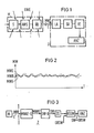
- the detector measured value diagram shown in FIG. 2 illustrates the detector measured values when the detector is at rest.
- a straight line indicates that, theoretically, the detector would have a straight-line measured value curve if it was at rest. In reality, however, the detector has a rest value that fluctuates more or less around this theoretical detector rest value MWR.
- MWG maximum fluctuation detector rest value
- a detector that is open to its surroundings shows significantly larger fluctuations MWO compared to the measured value fluctuations MWG.
- a functional detector is always exposed to temperature fluctuations, slight air currents, normal smoke changes, etc., which cause these fluctuations in the measured value by an imaginary idle value. If these statistical fluctuations fall below a certain, for example empirically determined value, it can be assumed that the detector is no longer connected to its environment, even though the detector was recognized as intact during the quiescent current monitoring. This is evaluated according to the invention.
- FIG. 3 shows a block diagram of the arrangement according to the invention using the example of a detector.
- the detector M is connected to the control center Z via the signal line L.
- the measured value change MWAE is determined from the detector measured values MW in a device for determining the measured value changes MWAE-E.
- this value is fed to a device SW-B which determines the fluctuation variable SW and supplies it to a downstream comparison device VGSW in a controlled manner via a timing element ZG.
- This comparison device VGSW is loaded with a limit value, a predetermined fluctuation variable GRSW. If the determined fluctuation variable SW is smaller than the predefined threshold for the fluctuation variable GRSW, the downstream display ANZ is activated in order to cause a fault display.
- a first memory MWSP is provided in the central station Z.
- the detector measured value MW of the detector M which is connected to the control center Z via the signal line L, reaches this memory MWSP.
- This detector measurement value MW is written into the memory MWSP as the current detector measurement value MWN and at the same time is given to an arithmetic logic unit ALU1.
- This logic unit ALU1 forms the absolute amount from the difference between the last measured value MWA, which is obtained from the measured value memory MWSP, and the current measured value MWN (IMWA-MWNI).
- This output value, the ALU1 is fed to a first comparator KOMP1 and compared with the value from the memory MAXSP connected downstream of the comparator KOMP1 for the maximum measured value change MWMAX.
- the memory for maximum measured value changes MAXSP is written with zero and the detector measured value memory MWSP with the current measured value MWN.
- the absolute difference (IMWA-MWNI) is formed and compared with the maximum value of the measured value change MWMAX from the MAXSP. The maximum of the two values is then stored in the memory for maximum measured value changes MAXSP. This decision is made with the demultiplexer DEM1, which is connected downstream of the comparator KOMP1.
- the memory for maximum measured value changes MAXSP is followed by a second comparator KOMP2 and a timing element ZG.
- the timing element ZG controls the comparator KOMP2 and at the same time resets the memory MAXSP to its initial position (zero) via input C. If the timer ZG has emitted a pulse to the comparator KOMP2 (enable input E) after a predetermined time T, the comparator compares the maximum fluctuation variable SWMAX from the memory MAXSP with a predetermined limit value for fluctuation variables GRSW. If the content of MAXSP is less than GRSW, a signal is given to the display ANZ for malfunction.
- the detector measured value memory MWSP and the arithmetic logic unit ALU1 correspond to the device for determining the measured value change MWAE-E:
- the device for forming the fluctuation variable SW-B has the comparator KOMP1 with a downstream demultiplexer DEM1 and the memory for maximum measured value changes MAXSP.
- the comparison device VGSW according to FIG. 3 corresponds to the second comparator KOMP2 in FIG.
- the absolute difference is not formed from two successive detector measured values and processed further as described according to FIG. 4.
- Two memories are provided in the control center Z, one for the maximum detector measurement value MAXSP and one for the minimum detector measurement value MINSP.
- the memory for the maximum detector measurement value MAXSP is initially set to zero, the memory MINSP to the largest possible measurement value.
- the current measured value MW which arrives from the detector M via the signal line L to the control center Z, is first compared with the memory MAXSP.
- a first comparator KOMP11 is provided, at one input of which the current detector measured value MW and at the other input of which the maximum measured value MWMAX stored in the MAXSP memory are present.
- the MAXSP memory is overwritten with the new measured value.
- the comparator KOMP11 outputs a "high” level H to the "enable” input E of the MAXSP memory and the new detector measured value present in the MAXSP memory is written. If the detector measured value is smaller, it is compared with the detector measured value MWMIN of the memory for minimum detector measured value MINSP. For this purpose, a "low” level is applied via the L output of the first comparator KOMP11 given the first input, the "Enable” input E of the second comparator KOMP12. This compares the detector measured value at the second input of the comparator KOMP1 with the minimum measured value from the MINSP memory.
- the new minimum measured value is written into the MINSP memory by the comparator KOMP12 emitting a signal to the "Enable" input E of the MINSP memory. Both memories lead with their outputs to a subordinate arithmetic logic. Unit ALU2, so that the maximum detector measured value MWMAX and the minimum detector measured value MWMIN from the corresponding memories (MAXSP and MINSP) are available. A time element ZG, that of the arithmetic. is assigned to the logic unit ALU2, causes the ALU2 to form the difference between the maximum and minimum detector measured value (MWMAX-MWMIN) and then to deliver the result SW to the third comparator KOMP2 connected downstream of the ALU2.
- the timer ZG also resets both memories MAXSP and MINSP to their initial values. For this reason, the timing element ZG is still connected to a respective "Clear" input C of the two memories MAXSP and MINSP.
- the third comparator KOMP2 compares the fluctuation variable SW from the ALU2 with the predefined limit value GRSW and triggers a fault display ANZ as soon as the fluctuation variable SW is smaller than the limit value GRSW.
Landscapes
- Physics & Mathematics (AREA)
- General Physics & Mathematics (AREA)
- Emergency Management (AREA)
- Computer Security & Cryptography (AREA)
- Optics & Photonics (AREA)
- Business, Economics & Management (AREA)
- Engineering & Computer Science (AREA)
- Alarm Systems (AREA)
- Fire-Detection Mechanisms (AREA)
- Fire Alarms (AREA)
- Testing And Monitoring For Control Systems (AREA)
- Burglar Alarm Systems (AREA)
- Cultivation Receptacles Or Flower-Pots, Or Pots For Seedlings (AREA)
Priority Applications (1)
| Application Number | Priority Date | Filing Date | Title |
|---|---|---|---|
| AT82104677T ATE22499T1 (de) | 1981-06-12 | 1982-05-27 | Verfahren und anordnung zur stoerungserkennung in gefahren-, insbesondere brandmeldeanlagen. |
Applications Claiming Priority (2)
| Application Number | Priority Date | Filing Date | Title |
|---|---|---|---|
| DE19813123451 DE3123451A1 (de) | 1981-06-12 | 1981-06-12 | Verfahren und anordnung zur stoerungserkennung in gefahren-, insbesondere brandmeldeanlagen |
| DE3123451 | 1981-06-12 |
Publications (3)
| Publication Number | Publication Date |
|---|---|
| EP0067339A2 EP0067339A2 (de) | 1982-12-22 |
| EP0067339A3 EP0067339A3 (en) | 1983-09-28 |
| EP0067339B1 true EP0067339B1 (de) | 1986-09-24 |
Family
ID=6134610
Family Applications (1)
| Application Number | Title | Priority Date | Filing Date |
|---|---|---|---|
| EP82104677A Expired EP0067339B1 (de) | 1981-06-12 | 1982-05-27 | Verfahren und Anordnung zur Störungserkennung in Gefahren-, insbesondere Brandmeldeanlagen |
Country Status (7)
| Country | Link |
|---|---|
| US (1) | US4543565A (da) |
| EP (1) | EP0067339B1 (da) |
| AT (1) | ATE22499T1 (da) |
| BR (1) | BR8203463A (da) |
| DE (2) | DE3123451A1 (da) |
| DK (1) | DK159028C (da) |
| NO (1) | NO156026C (da) |
Cited By (2)
| Publication number | Priority date | Publication date | Assignee | Title |
|---|---|---|---|---|
| DE3909073A1 (de) * | 1989-03-20 | 1990-09-27 | Waldemar Marinitsch | Verfahren und schaltungsanordnung zur dauerfailsafepruefung einer infrarot-sensoreinrichtung |
| WO2024046733A1 (en) | 2022-08-31 | 2024-03-07 | Hypro Innovation Gmbh | Absorbent thermal effect pad |
Families Citing this family (26)
| Publication number | Priority date | Publication date | Assignee | Title |
|---|---|---|---|---|
| US4543643A (en) * | 1982-05-28 | 1985-09-24 | Minolta Camera | Copying magnification setting device for an electrophotographic copying apparatus |
| DE3405857A1 (de) * | 1983-02-24 | 1984-08-30 | Hochiki K.K., Tokio/Tokyo | Feueralarmsystem |
| JPS59172094A (ja) * | 1983-03-21 | 1984-09-28 | 能美防災株式会社 | 煙検出機能試験装置を備えた光電式煙感知器 |
| JPS59187246A (ja) * | 1983-04-08 | 1984-10-24 | Nohmi Bosai Kogyo Co Ltd | 光電式煙感知器の機能検査装置 |
| JPS60144458U (ja) * | 1984-03-05 | 1985-09-25 | ホーチキ株式会社 | 火災検出装置 |
| JPH079680B2 (ja) * | 1985-04-01 | 1995-02-01 | ホーチキ株式会社 | アナログ火災報知装置 |
| JPS61237197A (ja) * | 1985-04-12 | 1986-10-22 | ホーチキ株式会社 | 火災警報装置 |
| DE3677416D1 (de) * | 1985-05-24 | 1991-03-14 | Siemens Ag | Einbruchmeldeanlage. |
| JPS6219999A (ja) * | 1985-07-18 | 1987-01-28 | ホーチキ株式会社 | 火災報知装置 |
| US4860351A (en) * | 1986-11-05 | 1989-08-22 | Ibm Corporation | Tamper-resistant packaging for protection of information stored in electronic circuitry |
| US5117457A (en) * | 1986-11-05 | 1992-05-26 | International Business Machines Corp. | Tamper resistant packaging for information protection in electronic circuitry |
| US4916432A (en) * | 1987-10-21 | 1990-04-10 | Pittway Corporation | Smoke and fire detection system communication |
| US5138562A (en) * | 1988-04-14 | 1992-08-11 | Fike Corporation | Environmental protection system useful for the fire detection and suppression |
| JP2758671B2 (ja) * | 1989-01-20 | 1998-05-28 | ホーチキ株式会社 | 火災判断装置 |
| DE3904979A1 (de) * | 1989-02-18 | 1990-08-23 | Beyersdorf Hartwig | Verfahren zum betrieb eines ionisationsrauchmelders und ionisationsrauchmelder |
| US5189399A (en) * | 1989-02-18 | 1993-02-23 | Hartwig Beyersdorf | Method of operating an ionization smoke alarm and ionization smoke alarm |
| JP3202793B2 (ja) * | 1992-05-28 | 2001-08-27 | 能美防災株式会社 | 火災感知器の感度測定装置 |
| JP3213661B2 (ja) * | 1993-11-25 | 2001-10-02 | 能美防災株式会社 | 火災検出装置 |
| JP3184429B2 (ja) * | 1995-06-30 | 2001-07-09 | ホーチキ株式会社 | 防災監視システムの端末感知装置 |
| JP3729643B2 (ja) * | 1998-06-15 | 2005-12-21 | 能美防災株式会社 | 火災報知設備 |
| EP1555642B1 (en) * | 2002-10-10 | 2007-09-05 | Valery Vasilievich Ovchinnikov | Method for forming and transmitting signals |
| DE102011118770B3 (de) * | 2011-11-17 | 2013-04-04 | Hekatron Vertriebs Gmbh | Gefahrenmelder |
| ITMI20120332A1 (it) * | 2012-03-02 | 2013-09-03 | St Microelectronics Srl | Caricatore di batterie. |
| EP2720051B1 (de) * | 2012-10-10 | 2015-01-21 | Sick Ag | Sicherheitssystem |
| CN111506029B (zh) * | 2020-04-10 | 2023-11-24 | 王思盛 | 一种工业控制方法及装置 |
| EP4246483A1 (de) | 2022-03-18 | 2023-09-20 | Siemens Schweiz AG | Brandmelder mit unbeheizten thermistoren, insbesondere ntcs, zur erfassung thermischer fluktuationen im bereich der eintrittsöffnungen sowie korrespondierendes verfahren |
Family Cites Families (7)
| Publication number | Priority date | Publication date | Assignee | Title |
|---|---|---|---|---|
| DE2113536A1 (de) * | 1971-03-16 | 1972-09-21 | Herrmann Hans Dipl Ing Dr | Verfahren zur UEberweisung und/oder Pruefung von analogen Messkanaelen |
| DE2147022A1 (de) * | 1971-09-21 | 1973-04-05 | Licentia Gmbh | Schaltungsanordnung zur erzielung einer groesseren empfindlichkeit bei einer stoerwertmeldeanlage mit schwankenden stoerpegeln |
| DE2341087C3 (de) * | 1973-08-14 | 1979-09-27 | Siemens Ag, 1000 Berlin Und 8000 Muenchen | Automatische Brandmeldeanlage |
| DE2817089B2 (de) * | 1978-04-19 | 1980-12-18 | Siemens Ag, 1000 Berlin Und 8000 Muenchen | Gefahrenmeldeanlage |
| US4263583A (en) * | 1978-12-19 | 1981-04-21 | Richard Wyckoff | Digital alarm system with variable alarm hysteresis |
| US4283717A (en) * | 1979-10-01 | 1981-08-11 | Digital Monitoring Products | Monitoring system for a direct-wire alarm system |
| US4313114A (en) * | 1980-05-30 | 1982-01-26 | Leupold & Stevens, Inc. | Liquid level recorder apparatus and method for storing level differences in memory |
-
1981
- 1981-06-12 DE DE19813123451 patent/DE3123451A1/de not_active Withdrawn
-
1982
- 1982-05-05 US US06/375,318 patent/US4543565A/en not_active Expired - Fee Related
- 1982-05-27 EP EP82104677A patent/EP0067339B1/de not_active Expired
- 1982-05-27 AT AT82104677T patent/ATE22499T1/de active
- 1982-05-27 DE DE8282104677T patent/DE3273421D1/de not_active Expired
- 1982-06-07 NO NO821901A patent/NO156026C/no unknown
- 1982-06-11 BR BR8203463A patent/BR8203463A/pt unknown
- 1982-06-11 DK DK263082A patent/DK159028C/da not_active IP Right Cessation
Cited By (2)
| Publication number | Priority date | Publication date | Assignee | Title |
|---|---|---|---|---|
| DE3909073A1 (de) * | 1989-03-20 | 1990-09-27 | Waldemar Marinitsch | Verfahren und schaltungsanordnung zur dauerfailsafepruefung einer infrarot-sensoreinrichtung |
| WO2024046733A1 (en) | 2022-08-31 | 2024-03-07 | Hypro Innovation Gmbh | Absorbent thermal effect pad |
Also Published As
| Publication number | Publication date |
|---|---|
| DE3273421D1 (en) | 1986-10-30 |
| EP0067339A2 (de) | 1982-12-22 |
| EP0067339A3 (en) | 1983-09-28 |
| NO156026C (no) | 1987-07-08 |
| BR8203463A (pt) | 1983-06-07 |
| NO821901L (no) | 1982-12-13 |
| DK159028C (da) | 1991-02-18 |
| DK263082A (da) | 1982-12-13 |
| NO156026B (no) | 1987-03-30 |
| ATE22499T1 (de) | 1986-10-15 |
| US4543565A (en) | 1985-09-24 |
| DK159028B (da) | 1990-08-20 |
| DE3123451A1 (de) | 1982-12-30 |
Similar Documents
| Publication | Publication Date | Title |
|---|---|---|
| EP0067339B1 (de) | Verfahren und Anordnung zur Störungserkennung in Gefahren-, insbesondere Brandmeldeanlagen | |
| EP0070449B1 (de) | Verfahren und Anordnung zur Erhöhung der Ansprechempfindlichkeit und der Störsicherheit in einer Gefahren-, insbesondere Brandmeldeanlage | |
| DE2817089B2 (de) | Gefahrenmeldeanlage | |
| EP0248298B1 (de) | Gefahrenmeldeanlage | |
| EP0121048B1 (de) | Schaltungsanordnung zur Störpegel-Überwachung von Meldern, die in einer Gefahrenmeldeanlage angeordnet sind | |
| EP3381020A1 (de) | Verfahren zum bestimmen von schwellenwerten einer zustandsüberwachungseinheit für eine brandmelder- und/oder löschsteuerzentrale sowie zustandsüberwachungseinheit und system damit | |
| EP0066200B1 (de) | Verfahren und Anordnung zur Revision in einem Gefahren-, insbesondere Brandmeldesystem | |
| EP0004909B1 (de) | Gefahrenmeldeanlage | |
| EP2613463B1 (de) | Verfahren zur überwachung eines transmitters und entsprechender transmitter | |
| CH660638A5 (de) | Multiplex-gefahrenmeldeanlage. | |
| EP2393073B1 (de) | Verfahren zum Betreiben einer Gefahrenmeldeanlage | |
| WO1988005570A1 (fr) | Procede et dispositif de surveillance d'organes de commande terminaux commandes par un ordinateur | |
| DE69913435T2 (de) | Brandmeldeanlage | |
| DE69310431T2 (de) | Brandmeldeanlage | |
| EP0098554B1 (de) | Verfahren und Einrichtung zur automatischen Abfrage des Meldermesswerts und der Melderkennung in einer Gefahrenmeldeanlage | |
| EP0098552B1 (de) | Verfahren und Einrichtung zur automatischen Abfrage des Meldermesswerts und der Melderkennung in einer Gefahrenmeldeanlage | |
| EP0254125B1 (de) | Gefahrenmeldeanlage | |
| DE3614692C2 (da) | ||
| DE3225032C2 (de) | Verfahren und Einrichtung zur wahlweisen automatischen Abfrage der Melderkennung oder des Meldermeßwerts in einer Gefahrenmeldeanlage | |
| EP0098553B1 (de) | Verfahren und Einrichtung zur automatischen Abfrage des Meldermesswerts und/oder der Melderkennung in einer Gefahrenmeldeanlage | |
| DE3141220C2 (da) | ||
| DE19640739C1 (de) | Alarmspeicher-Schaltungsanordnung für Öffnungsmelder | |
| DE19850579C2 (de) | Verfahren zum Betreiben eines Meßumformers | |
| DE3225044C2 (de) | Verfahren und Einrichtung zur automatischen Abfrage des Meldermeßwerts und der Melderkennung in einer Gefahrenmeldeanlage | |
| EP1756680B1 (de) | Verfahren zum betrieb einer recheneinheit sowie signal zur verarbeitung in einer recheneinheit |
Legal Events
| Date | Code | Title | Description |
|---|---|---|---|
| PUAI | Public reference made under article 153(3) epc to a published international application that has entered the european phase |
Free format text: ORIGINAL CODE: 0009012 |
|
| AK | Designated contracting states |
Designated state(s): AT BE DE FR IT NL SE |
|
| PUAL | Search report despatched |
Free format text: ORIGINAL CODE: 0009013 |
|
| AK | Designated contracting states |
Designated state(s): AT BE DE FR IT NL SE |
|
| 17P | Request for examination filed |
Effective date: 19831222 |
|
| GRAA | (expected) grant |
Free format text: ORIGINAL CODE: 0009210 |
|
| AK | Designated contracting states |
Kind code of ref document: B1 Designated state(s): AT BE DE FR IT NL SE |
|
| REF | Corresponds to: |
Ref document number: 22499 Country of ref document: AT Date of ref document: 19861015 Kind code of ref document: T |
|
| REF | Corresponds to: |
Ref document number: 3273421 Country of ref document: DE Date of ref document: 19861030 |
|
| ET | Fr: translation filed | ||
| ITF | It: translation for a ep patent filed | ||
| PLBI | Opposition filed |
Free format text: ORIGINAL CODE: 0009260 |
|
| 26 | Opposition filed |
Opponent name: DETECTOMAT GMBH Effective date: 19870606 |
|
| NLR1 | Nl: opposition has been filed with the epo |
Opponent name: DETECTOMAT GMBH |
|
| PG25 | Lapsed in a contracting state [announced via postgrant information from national office to epo] |
Ref country code: SE Effective date: 19880528 |
|
| ITTA | It: last paid annual fee | ||
| PLBN | Opposition rejected |
Free format text: ORIGINAL CODE: 0009273 |
|
| STAA | Information on the status of an ep patent application or granted ep patent |
Free format text: STATUS: OPPOSITION REJECTED |
|
| 27O | Opposition rejected |
Effective date: 19911109 |
|
| NLR2 | Nl: decision of opposition | ||
| EUG | Se: european patent has lapsed |
Ref document number: 82104677.8 Effective date: 19890510 |
|
| PGFP | Annual fee paid to national office [announced via postgrant information from national office to epo] |
Ref country code: AT Payment date: 20010411 Year of fee payment: 20 |
|
| PGFP | Annual fee paid to national office [announced via postgrant information from national office to epo] |
Ref country code: NL Payment date: 20010514 Year of fee payment: 20 |
|
| PGFP | Annual fee paid to national office [announced via postgrant information from national office to epo] |
Ref country code: FR Payment date: 20010522 Year of fee payment: 20 |
|
| PGFP | Annual fee paid to national office [announced via postgrant information from national office to epo] |
Ref country code: BE Payment date: 20010608 Year of fee payment: 20 |
|
| PGFP | Annual fee paid to national office [announced via postgrant information from national office to epo] |
Ref country code: DE Payment date: 20010720 Year of fee payment: 20 |
|
| BE20 | Be: patent expired |
Free format text: 20020527 *SIEMENS A.G. BERLIN UND MUNCHEN |
|
| PG25 | Lapsed in a contracting state [announced via postgrant information from national office to epo] |
Ref country code: NL Free format text: LAPSE BECAUSE OF EXPIRATION OF PROTECTION Effective date: 20020527 Ref country code: AT Free format text: LAPSE BECAUSE OF EXPIRATION OF PROTECTION Effective date: 20020527 |
|
| NLV7 | Nl: ceased due to reaching the maximum lifetime of a patent |
Effective date: 20020527 |
|
| PLAB | Opposition data, opponent's data or that of the opponent's representative modified |
Free format text: ORIGINAL CODE: 0009299OPPO |