EP0061067B1 - Verfahren zum Einschliessen verbrauchter Brennstäbe eines Kernreaktors in einem Behälter aus Kupfer - Google Patents
Verfahren zum Einschliessen verbrauchter Brennstäbe eines Kernreaktors in einem Behälter aus Kupfer Download PDFInfo
- Publication number
- EP0061067B1 EP0061067B1 EP82101891A EP82101891A EP0061067B1 EP 0061067 B1 EP0061067 B1 EP 0061067B1 EP 82101891 A EP82101891 A EP 82101891A EP 82101891 A EP82101891 A EP 82101891A EP 0061067 B1 EP0061067 B1 EP 0061067B1
- Authority
- EP
- European Patent Office
- Prior art keywords
- container
- lid
- copper
- fuel rods
- powder
- Prior art date
- Legal status (The legal status is an assumption and is not a legal conclusion. Google has not performed a legal analysis and makes no representation as to the accuracy of the status listed.)
- Expired
Links
- RYGMFSIKBFXOCR-UHFFFAOYSA-N Copper Chemical compound [Cu] RYGMFSIKBFXOCR-UHFFFAOYSA-N 0.000 title claims description 72
- 229910052802 copper Inorganic materials 0.000 title claims description 51
- 239000010949 copper Substances 0.000 title claims description 51
- 238000000034 method Methods 0.000 title claims description 27
- 239000002915 spent fuel radioactive waste Substances 0.000 title claims description 10
- 239000000446 fuel Substances 0.000 claims description 50
- 239000002775 capsule Substances 0.000 claims description 40
- 239000000843 powder Substances 0.000 claims description 29
- 238000000462 isostatic pressing Methods 0.000 claims description 26
- 239000000463 material Substances 0.000 claims description 16
- 125000006850 spacer group Chemical group 0.000 claims description 13
- 230000001427 coherent effect Effects 0.000 claims description 12
- 230000007797 corrosion Effects 0.000 claims description 6
- 238000005260 corrosion Methods 0.000 claims description 6
- 230000000712 assembly Effects 0.000 claims description 3
- 238000000429 assembly Methods 0.000 claims description 3
- 239000007789 gas Substances 0.000 description 14
- UFHFLCQGNIYNRP-UHFFFAOYSA-N Hydrogen Chemical compound [H][H] UFHFLCQGNIYNRP-UHFFFAOYSA-N 0.000 description 10
- 229910000831 Steel Inorganic materials 0.000 description 8
- 238000003825 pressing Methods 0.000 description 8
- 239000012798 spherical particle Substances 0.000 description 8
- 239000010959 steel Substances 0.000 description 8
- 238000003466 welding Methods 0.000 description 6
- 229910052751 metal Inorganic materials 0.000 description 5
- 239000002184 metal Substances 0.000 description 5
- 239000000203 mixture Substances 0.000 description 5
- XKRFYHLGVUSROY-UHFFFAOYSA-N Argon Chemical compound [Ar] XKRFYHLGVUSROY-UHFFFAOYSA-N 0.000 description 4
- 239000002253 acid Substances 0.000 description 4
- 230000015572 biosynthetic process Effects 0.000 description 4
- 238000010438 heat treatment Methods 0.000 description 4
- 239000002901 radioactive waste Substances 0.000 description 4
- 238000005406 washing Methods 0.000 description 4
- 229910001093 Zr alloy Inorganic materials 0.000 description 3
- 229910001220 stainless steel Inorganic materials 0.000 description 3
- 239000010935 stainless steel Substances 0.000 description 3
- 230000007704 transition Effects 0.000 description 3
- QPLDLSVMHZLSFG-UHFFFAOYSA-N Copper oxide Chemical class [Cu]=O QPLDLSVMHZLSFG-UHFFFAOYSA-N 0.000 description 2
- MHAJPDPJQMAIIY-UHFFFAOYSA-N Hydrogen peroxide Chemical compound OO MHAJPDPJQMAIIY-UHFFFAOYSA-N 0.000 description 2
- PNEYBMLMFCGWSK-UHFFFAOYSA-N aluminium oxide Inorganic materials [O-2].[O-2].[O-2].[Al+3].[Al+3] PNEYBMLMFCGWSK-UHFFFAOYSA-N 0.000 description 2
- 229910052786 argon Inorganic materials 0.000 description 2
- QVGXLLKOCUKJST-UHFFFAOYSA-N atomic oxygen Chemical compound [O] QVGXLLKOCUKJST-UHFFFAOYSA-N 0.000 description 2
- 230000001680 brushing effect Effects 0.000 description 2
- 239000000470 constituent Substances 0.000 description 2
- 230000007547 defect Effects 0.000 description 2
- 238000005530 etching Methods 0.000 description 2
- 230000004992 fission Effects 0.000 description 2
- 239000008187 granular material Substances 0.000 description 2
- 239000001307 helium Substances 0.000 description 2
- 229910052734 helium Inorganic materials 0.000 description 2
- SWQJXJOGLNCZEY-UHFFFAOYSA-N helium atom Chemical compound [He] SWQJXJOGLNCZEY-UHFFFAOYSA-N 0.000 description 2
- 239000001301 oxygen Substances 0.000 description 2
- 229910052760 oxygen Inorganic materials 0.000 description 2
- OOAWCECZEHPMBX-UHFFFAOYSA-N oxygen(2-);uranium(4+) Chemical compound [O-2].[O-2].[U+4] OOAWCECZEHPMBX-UHFFFAOYSA-N 0.000 description 2
- 239000002245 particle Substances 0.000 description 2
- 229910052698 phosphorus Inorganic materials 0.000 description 2
- 230000000630 rising effect Effects 0.000 description 2
- 238000005488 sandblasting Methods 0.000 description 2
- 239000000126 substance Substances 0.000 description 2
- FCTBKIHDJGHPPO-UHFFFAOYSA-N uranium dioxide Inorganic materials O=[U]=O FCTBKIHDJGHPPO-UHFFFAOYSA-N 0.000 description 2
- OAICVXFJPJFONN-UHFFFAOYSA-N Phosphorus Chemical compound [P] OAICVXFJPJFONN-UHFFFAOYSA-N 0.000 description 1
- RTAQQCXQSZGOHL-UHFFFAOYSA-N Titanium Chemical compound [Ti] RTAQQCXQSZGOHL-UHFFFAOYSA-N 0.000 description 1
- 238000011161 development Methods 0.000 description 1
- 230000018109 developmental process Effects 0.000 description 1
- 239000000156 glass melt Substances 0.000 description 1
- 229910010272 inorganic material Inorganic materials 0.000 description 1
- 239000011147 inorganic material Substances 0.000 description 1
- 239000011574 phosphorus Substances 0.000 description 1
- 239000011241 protective layer Substances 0.000 description 1
- 239000012857 radioactive material Substances 0.000 description 1
- 238000009419 refurbishment Methods 0.000 description 1
- 239000007787 solid Substances 0.000 description 1
- 239000010936 titanium Substances 0.000 description 1
- 229910052719 titanium Inorganic materials 0.000 description 1
Images
Classifications
-
- G—PHYSICS
- G21—NUCLEAR PHYSICS; NUCLEAR ENGINEERING
- G21F—PROTECTION AGAINST X-RADIATION, GAMMA RADIATION, CORPUSCULAR RADIATION OR PARTICLE BOMBARDMENT; TREATING RADIOACTIVELY CONTAMINATED MATERIAL; DECONTAMINATION ARRANGEMENTS THEREFOR
- G21F5/00—Transportable or portable shielded containers
- G21F5/005—Containers for solid radioactive wastes, e.g. for ultimate disposal
-
- G—PHYSICS
- G21—NUCLEAR PHYSICS; NUCLEAR ENGINEERING
- G21F—PROTECTION AGAINST X-RADIATION, GAMMA RADIATION, CORPUSCULAR RADIATION OR PARTICLE BOMBARDMENT; TREATING RADIOACTIVELY CONTAMINATED MATERIAL; DECONTAMINATION ARRANGEMENTS THEREFOR
- G21F9/00—Treating radioactively contaminated material; Decontamination arrangements therefor
- G21F9/28—Treating solids
- G21F9/34—Disposal of solid waste
- G21F9/36—Disposal of solid waste by packaging; by baling
Definitions
- the invention relates to a method for enclosing spent fuel rods of a nuclear reactor in a copper container according to the preamble of claim 1.
- spent fuel rods from a nuclear reactor are directly, i. H. without refurbishment, enclosed in sealed containers made of corrosion-resistant material.
- spent fuel rods are placed in a copper container and embedded in lead in the container by supplying molten lead to the container, which then solidifies in the container.
- the container is then provided with a copper lid which is welded to the container to form a tight seam.
- a method for enclosing spent fuel rods is known from the publication »speaking room « 113 (1980), page 756 ff, in which the fuel rods are first enclosed in a steel container. This steel container is then introduced loosely, that is to say without additional embedding material, into a receptacle made of alumina. The alumina jar is then capped and the entire unit is hot isostatically pressed.
- a method for the containment of radioactive waste in which a body containing radioactive waste prepared in a certain way is placed in a copper capsule and embedded therein in copper powder, whereupon the entire unit is hot isostatically pressed.
- a prerequisite for this method is that the radioactive material of the body introduced into the copper shell is already enclosed in a material that is resistant to the environment, namely in a solidified glass melt or a sintered oxidic or other inorganic material.
- the radioactive waste must be converted into a stable and pressure-resistant body by a complex other method.
- the invention has for its object to develop a simple method in relation to the known methods of the type mentioned, by which the spent fuel rods are protected in a very resistant to corruption attacks and tightly sealed to the outside.
- the invention is based on the finding that considerable advantages are achieved when copper powder is used instead of lead as embedding material for the spent fuel rods and when the container and the lid are closed by isostatic pressing.
- a higher resistance to corrosion attacks is achieved in that the solid copper body formed from the copper powder, the container and the lid is more resistant to corrosion than a copper container with a lead body arranged therein.
- copper is inherently more resistant than lead and on the other hand to the fact that the protective layers consist of a uniform material.
- Another advantage is that the inside of the container can be manufactured free of cavitation, which is hardly possible when pouring lead into the container and welding a lid.
- Another advantage is that the seam between the container and the lid in the method according to the invention is completely tight and completely reliable.
- the materials of the container and lid merge into one another without a joint or a transition point with a different material composition being present between the container and the lid.
- the welding of copper parts with a large wall thickness is associated with great difficulties and results in a seam which has a different structure than the adjacent material. The seam can therefore become a weakened area in the closed container.
- the gas-tight capsule can normally remain on the finished pressed body when it is deposited for final storage.
- the capsule can be made from sheet metal of the same quality as the container, i.e. H. made of copper. This considerably reduces the probability that a coherent material defect or a defect in the copper material can occur.
- the outer capsule can also be made of another material that provides additional corrosion protection for copper, such as. B. stainless steel or titanium.
- the container, the lid and the copper powder are preferably made of a high-purity quality copper with a low oxygen content, at least 99.95% Cu (including small amounts of Ag), a so-called OFHC type (Oxygen Free High Conductivity). It is believed that such quality gives the finished product good resistance to corrosion.
- high-purity copper can be used, which has been deoxidized with small amounts of phosphorus (max. 0.015% P).
- the particles of the copper powder are preferably spherical or at least predominantly spherical. Particles with such a shape have good fluidity and thus result in a high degree of filling.
- the fill Degree of efficiency can be improved by using spherical powder with at least two different grain sizes.
- a suitable grain size for one of the two fractions is 0.5-1.5 mm and for the other fraction 0.1-0.2 mm.
- the latter fraction can alternatively be a graded fraction with a maximum grain size of 0.2 mm.
- the fact that the container and / or the fuel assemblies are exposed to slight impacts or vibrations when filled can further improve the filling level of the copper powder.
- a vibrating ramming device can be temporarily placed on or in the filled copper powder for the same purpose.
- the isostatic pressing to form the coherent, tight unit from the container, lid and powder preferably takes place at a pressure of at least 10 MPa and at a temperature of 500-800 ° C.
- the spacer elements are spacers, usually made of stainless steel, in which the fuel rods are combined to form fuel bundles, are arranged in the nuclear reactor during operation. After the fuel rods in the reactor have been used up, the fuel bundles can be placed in the copper container without any assembly work and can be treated for containment and final storage in accordance with the present invention.
- the spacer elements consist of copper. This embodiment is particularly suitable when the fuel rods are dismantled, i. H. are not arranged in the form of bundles in spacers. Spacers made of copper with the poured-in copper powder surrounding them result in a homogeneous unit without any transition points with a different structure.
- the copper components are one by isostatic pressing at a temperature lower than that used in the final pressing Subjected to creep.
- the copper components are either arranged in the sealed, gas-tight capsule that is used in the final pressing, or they are - if the capsule is not used - arranged in such a way that the lid is connected to the container in a gastight manner.
- a pressure of at least 10 MPa and a temperature of 300-500 ° C is preferably used.
- the copper parts By isostatically pressing the copper parts in this way at a temperature lower than the temperature used in the final assembly of the parts, one obtains an effective support pressure on the fuel rods of the fuel rods during further heating.
- This can eliminate or at least substantially reduce the risk that the gas in the fuel pipes, when heated further to the temperature required for the formation of a coherent unit from the copper constituents powder, container and lid, causes such a pressure that in an expansion fracture occurs in the fuel pipes.
- the fuel pipes contain gases, including helium and fission gases, which already have a pressure of 50-80 bar in the fuel rods at room temperature can cause.
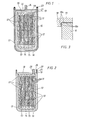
- a plurality of spent fuel rods 11 of a nuclear reactor are arranged in a container 10 made of copper.
- the fuel rods which consist of circaloy tubes with uranium dioxide tablets stacked therein, remain in the spacers 12 which hold the fuel rods of each fuel bundle together in the nuclear reactor. 1 and 2, four fuel bundles 13,14,15 and 16 can be seen.
- the fuel bundles can possibly be placed on supports, not shown, on the bottom of the container or on a bed of copper powder.
- the container is then whole with vibration with a powder mixture 17 of 70 parts by weight of a powder with spherical particles with a diameter of 0.5-1.5 mm and 30 parts by weight of a powder with spherical particles with a diameter of 0.1-0, 2 mm filled.
- a copper lid 18 is then placed on the container.
- Containers, lids and powder consist of the copper quality mentioned at the beginning, which contains 99.95% Cu (including small amounts of Ag).
- the part 19 of the lid, which rests on the container, is designed step-like.
- the lid has a central, lower part 20 which projects into the container.
- the abutting surfaces 10a and 18a of the container 10 and lid 18 are textured, as can be seen in FIG. 3.
- the surfaces are cleaned well before the lid is placed on the container and freed of oxide with acid.
- the container with lid and contents is placed in a capsule 21 made of copper sheet or sheet steel, the lid 22 made of copper sheet or sheet steel is welded tight to form a gas-tight seam 23.
- the lid is provided with a pipe socket 24 made of copper or steel, which can be connected to a vacuum pump for the purpose of evacuating the capsule with its contents. After the evacuation, the capsule is closed by welding the pipe socket above the upper surface of the lid.
- the capsule with content is hot isostatically pressed in two steps with a gas, e.g. B. argon, as a pressure medium in an oven for isostatic pressing of the type described in DE-A-2 747 951.
- a gas e.g. B. argon
- the capsule is exposed to a pressure of 80 MPa and a temperature of 450-500 ° C for 2-10 hours.
- This causes the copper of the container, the lid and the powder to creep, which means that the filling made of the copper powder gives the fuel rods an effective support pressure, which prevents expansion fracture in the Zircaloy tubes, which could occur due to the pressure of the gas in these pipes increases with further heating.
- this treatment does not result in the powder granules, the container and the lid forming a fully bonded unit.
- a mixture 17 which consists of 55 parts by weight of a powder with spherical particles with a diameter of 0.8-1.0 mm and 45 parts by weight of a powder with spherical particles with a diameter of 0.2 mm and below consists. This gives a bulk density of 81% of the theoretical density.
- the capsule 21 and its contents have been evacuated, the capsule is heated to 350 ° C., after which it is filled with hydrogen gas at a pressure of 0.1 MPa. After maintaining this temperature for half an hour, the capsule is evacuated and refilled with hydrogen gas.
- This treatment with hydrogen gas at 350 ° C. is carried out several times, for example seven times, expediently with a successively extended treatment time, e.g.
- the hydrogen gas treatment causes a reduction in any copper oxides that are present.
- the capsule is evacuated and, as in the case described above, sealed.
- the isostatic pressing takes place in the first step at 400-450 ° C and in the second step at 250 ° C. This alternative embodiment is otherwise carried out under the same conditions as in the previously described case.
- the container 10 and the lid 18 are each provided with a flange 25 and 26, respectively.
- the flanges 25 and 26 are joined to form a gas-tight seam 27 by welding or cold pressing.
- the lid is provided with a pipe socket 28 made of copper, which is gastight after the evacuation of the container Degree of efficiency can be improved by using spherical powder with at least two different grain sizes.
- a suitable grain size for one of the two fractions is 0.5-1.5 mm and for the other fraction 0.1-0.2 mm.
- the latter fraction can alternatively be a graded fraction with a maximum grain size of 0.2 mm.
- the fact that the container and / or the fuel assemblies are exposed to slight impacts or vibrations when filled can further improve the filling level of the copper powder.
- a vibrating ramming device can be temporarily placed on or in the filled copper powder for the same purpose.
- the isostatic pressing to form the coherent, tight unit from the container, lid and powder preferably takes place at a pressure of at least 10 MPa and at a temperature of 500-800 ° C.
- the spacer elements are spacers, usually made of stainless steel, in which the fuel rods are combined to form fuel bundles, are arranged in the nuclear reactor during operation. After the fuel rods in the reactor have been used up, the fuel bundles can be placed in the copper container without any assembly work and can be treated for containment and final storage in accordance with the present invention.
- the spacer elements consist of copper. This embodiment is particularly suitable when the fuel rods are dismantled, i. H. are not arranged in the form of bundles in spacers. Spacers made of copper with the poured-in copper powder surrounding them result in a homogeneous unit without any transition points with a different structure.
- the copper components are one by isostatic pressing at a temperature lower than that used in the final pressing Subjected to creep.
- the copper components are either arranged in the sealed, gas-tight capsule that is used in the final pressing, or they are - if the capsule is not used - arranged in such a way that the lid is connected to the container in a gastight manner.
- a pressure of at least 10 MPa and a temperature of 300500 ° C. is preferably used.
- the copper parts By isostatically pressing the copper parts in this way at a temperature lower than the temperature used in the final assembly of the parts, one obtains an effective support pressure on the fuel rods of the fuel rods during further heating.
- This can eliminate or at least substantially reduce the risk that the gas in the fuel pipes, when heated further to the temperature required for the formation of a coherent unit from the copper constituents powder, container and lid, causes such a pressure that in an expansion fracture occurs in the fuel pipes.
- the fuel pipes contain gases, including helium and fission gases, which already have a pressure of 50-80 bar in the fuel rods at room temperature can cause.
- a plurality of spent fuel rods 11 of a nuclear reactor are arranged in a container 10 made of copper.
- the fuel rods which consist of zircaloy tubes with uranium dioxide tablets stacked therein, remain in the spacers 12, which hold the fuel rods of each fuel bundle together in the nuclear reactor.
- four Brenneiementbündei 13,14,15 and 16 can be seen.
- the fuel bundles can possibly be placed on supports, not shown, on the bottom of the container or on a bed of copper powder.
- the container is then whole with vibration with a powder mixture 17 of 70 parts by weight of a powder with spherical particles with a diameter of 0.5-1.5 mm and 30 parts by weight of a powder with spherical particles with a diameter of 0.1-0, 2 mm filled.
- a copper lid 18 is then placed on the container.
- Containers, lids and powder consist of the copper quality mentioned at the beginning, which contains 99.95% Cu (including small amounts of Ag).
- the part 19 of the lid, which rests on the container, is designed step-like.
- the lid has a central, lower part 20 which projects into the container.
- the abutting surfaces 10a and 18a of the container 10 and lid 18 are textured, as can be seen in FIG. 3.
- the surfaces are cleaned well before the lid is placed on the container and freed of oxide with acid.
- the container with lid and contents is placed in a capsule 21 made of copper sheet or sheet steel, the lid 22 made of copper sheet or sheet steel is welded tight to form a gas-tight seam 23.
- the lid is provided with a pipe socket 24 made of copper or steel, which can be connected to a vacuum pump for the purpose of evacuating the capsule with its contents. After the evacuation, the capsule is closed by welding the pipe socket above the upper surface of the lid.
- the capsule with content is hot isostatically pressed in two steps with a gas, e.g. B. argon, as a pressure medium in an oven for isostatic pressing of the type described in DE-A-2 747 951.
- a gas e.g. B. argon
- the capsule is exposed to a pressure of 80 MPa and a temperature of 450-500 ° C for 2-10 hours.
- This causes the copper of the container, the lid and the powder to creep, which means that the filling made of the copper powder gives the fuel rods an effective support pressure, which prevents expansion fracture in the Zircaloy tubes, which could occur due to the pressure of the gas in these pipes increases with further heating.
- this treatment does not result in the powder granules, the container and the lid forming a fully bonded unit.
- a mixture 17 which consists of 55 parts by weight of a powder with spherical particles with a diameter of 0.8-1.0 mm and 45 parts by weight of a powder with spherical particles with a diameter of 0.2 mm and below consists. This gives a bulk density of 81% of the theoretical density.
- the capsule 21 and its contents have been evacuated, the capsule is heated to 350 ° C., after which it is filled with hydrogen gas at a pressure of 0.1 MPa. After maintaining this temperature for half an hour, the capsule is evacuated and refilled with hydrogen gas.
- This treatment with hydrogen gas at 350 ° C. is carried out several times, for example seven times, expediently with a successively extended treatment time, e.g.
- the hydrogen gas treatment causes a reduction in any copper oxides that are present.
- the capsule is evacuated and, as in the case described above, sealed.
- the isostatic pressing takes place in the first step at 400-450 ° C and in the second step at 250 ° C. This alternative embodiment is otherwise carried out under the same conditions as in the previously described case.
- the container 10 and the lid 18 are each provided with a flange 25 and 26, respectively.
- the flanges 25 and 26 are joined to form a gas-tight seam 27 by welding or cold pressing.
- the lid is provided with a pipe socket 28 made of copper, which is gastight after the evacuation of the container attached lid is closed. After closing, the closed container is isostatically pressed in two steps in the manner described for the closed capsule according to FIG. 1.
Landscapes
- Engineering & Computer Science (AREA)
- Physics & Mathematics (AREA)
- General Engineering & Computer Science (AREA)
- High Energy & Nuclear Physics (AREA)
- Environmental & Geological Engineering (AREA)
- Pressure Welding/Diffusion-Bonding (AREA)
- Press Drives And Press Lines (AREA)
- Filling Or Discharging Of Gas Storage Vessels (AREA)
- Powder Metallurgy (AREA)
Applications Claiming Priority (2)
| Application Number | Priority Date | Filing Date | Title |
|---|---|---|---|
| SE8101778 | 1981-03-20 | ||
| SE8101778A SE425707B (sv) | 1981-03-20 | 1981-03-20 | Sett att innesluta utbrenda kernbrenslestavar i en behallare av koppar |
Publications (2)
| Publication Number | Publication Date |
|---|---|
| EP0061067A1 EP0061067A1 (de) | 1982-09-29 |
| EP0061067B1 true EP0061067B1 (de) | 1985-11-13 |
Family
ID=20343383
Family Applications (1)
| Application Number | Title | Priority Date | Filing Date |
|---|---|---|---|
| EP82101891A Expired EP0061067B1 (de) | 1981-03-20 | 1982-03-10 | Verfahren zum Einschliessen verbrauchter Brennstäbe eines Kernreaktors in einem Behälter aus Kupfer |
Country Status (8)
| Country | Link |
|---|---|
| US (1) | US4491540A (ja) |
| EP (1) | EP0061067B1 (ja) |
| JP (1) | JPS57168200A (ja) |
| CA (1) | CA1190332A (ja) |
| DE (1) | DE3267356D1 (ja) |
| ES (1) | ES510536A0 (ja) |
| FI (1) | FI72008C (ja) |
| SE (1) | SE425707B (ja) |
Families Citing this family (26)
| Publication number | Priority date | Publication date | Assignee | Title |
|---|---|---|---|---|
| EP0077955A3 (de) * | 1981-10-28 | 1983-09-07 | Deutsche Gesellschaft für Wiederaufarbeitung von Kernbrennstoffen mbH | Brennelementbehälter zum Transportieren und/oder Lagern von Kernreaktorbrennelementen |
| DE3201884A1 (de) * | 1982-01-22 | 1983-08-04 | Deutsche Gesellschaft für Wiederaufarbeitung von Kernbrennstoffen mbH, 3000 Hannover | Verfahren zum verschliessen von radioaktive stoffe aufnehmenden behaeltern |
| DE3231747A1 (de) * | 1982-08-26 | 1984-03-01 | Deutsche Gesellschaft für Wiederaufarbeitung von Kernbrennstoffen mbH, 3000 Hannover | Trockenlagerbuechse fuer abgebrannte kernreaktorbrennelemente |
| DE8236359U1 (de) * | 1982-12-24 | 1983-06-30 | Deutsche Gesellschaft für Wiederaufarbeitung von Kernbrennstoffen mbH, 3000 Hannover | Lagerbehaelter fuer radioaktives material |
| DE3334660A1 (de) * | 1983-09-24 | 1985-04-11 | Steag Kernenergie Gmbh, 4300 Essen | Verfahren zum schliessen eines behaelters fuer die lagerung radioaktiver substanzen |
| US4623510A (en) * | 1983-10-28 | 1986-11-18 | Westinghouse Electric Corp. | Permanent disposal of radioactive particulate waste in cartridge containing ferromagnetic material |
| US4738799A (en) * | 1983-10-28 | 1988-04-19 | Westinghouse Electric Corp. | Permanent disposal of radioactive particulate waste |
| DE3344525A1 (de) * | 1983-12-09 | 1985-06-20 | Kernforschungsanlage Jülich GmbH, 5170 Jülich | Verfahren zur lagerung abgebrannter brennelemente |
| DE3503641A1 (de) * | 1984-07-24 | 1986-02-06 | Nationale Genossenschaft für die Lagerung radioaktiver Abfälle - NAGRA, Baden | Verfahren zum schliessen eines behaelters zur aufnahme von radioaktivem material und behaelter zur durchfuehrung des verfahrens |
| DE3720731A1 (de) * | 1986-06-25 | 1988-01-07 | Atomic Energy Of Australia | Einkapselung von abfallstoffen |
| FR2648611B2 (fr) * | 1988-12-12 | 1994-08-19 | Cogema | Conteneur de stockage pour dechets radioactifs |
| US4963317A (en) * | 1989-09-13 | 1990-10-16 | The United States Of America As Represented By The United States Department Of Energy | High loading uranium fuel plate |
| JPH087279B2 (ja) * | 1989-09-28 | 1996-01-29 | 動力灯・核燃料開発事業団 | 放射性廃棄物の処理用容器の真空脱気方法 |
| JP2547453B2 (ja) * | 1989-09-28 | 1996-10-23 | 動力灯・核燃料開発事業団 | 放射性金属廃棄物の減容処理方法 |
| US5401319A (en) * | 1992-08-27 | 1995-03-28 | Applied Materials, Inc. | Lid and door for a vacuum chamber and pretreatment therefor |
| US5488644A (en) * | 1994-07-13 | 1996-01-30 | General Electric Company | Spring assemblies for adjoining nuclear fuel rod containing ferrules and a spacer formed of the spring assemblies and ferrules |
| US5519747A (en) * | 1994-10-04 | 1996-05-21 | General Electric Company | Apparatus and methods for fabricating spacers for a nuclear fuel rod bundle |
| US5546437A (en) * | 1995-01-11 | 1996-08-13 | General Electric Company | Spacer for nuclear fuel rods |
| US5566217A (en) * | 1995-01-30 | 1996-10-15 | General Electric Company | Reduced height spacer for nuclear fuel rods |
| US5675621A (en) * | 1995-08-17 | 1997-10-07 | General Electric Company | Reduced height flat spring spacer for nuclear fuel rods |
| US20060070477A1 (en) * | 2004-10-04 | 2006-04-06 | Roger Serzen | Adaptive wheelchair joystick |
| DE102004059216B3 (de) * | 2004-12-09 | 2006-06-01 | Forschungszentrum Karlsruhe Gmbh | Verfahren zur Einlagerung radioaktiver Reststoffe, Behälter dafür und seine Verwendung |
| SE531261C2 (sv) * | 2007-05-25 | 2009-02-03 | Olle Grinder | Kapsel avsedd för slutförvaring av utbränt kärnbränsle |
| US9406409B2 (en) * | 2013-03-06 | 2016-08-02 | Nuscale Power, Llc | Managing nuclear reactor spent fuel rods |
| KR101754754B1 (ko) * | 2016-06-21 | 2017-07-07 | 한국원자력연구원 | 사용후 핵연료 건식 저장 용기 |
| CN109963663B (zh) * | 2016-11-18 | 2022-04-08 | 萨尔瓦托雷·莫里卡 | 用于废物处理的受控hip容器塌缩 |
Family Cites Families (11)
| Publication number | Priority date | Publication date | Assignee | Title |
|---|---|---|---|---|
| BE622903A (ja) * | 1961-10-09 | |||
| US4090873A (en) * | 1975-01-23 | 1978-05-23 | Nippon Gakki Seizo Kabushiki Kaisha | Process for producing clad metals |
| FR2375695A1 (fr) * | 1976-12-21 | 1978-07-21 | Asea Ab | Procede pour le traitement de dechets radioactifs |
| US4209420A (en) * | 1976-12-21 | 1980-06-24 | Asea Aktiebolag | Method of containing spent nuclear fuel or high-level nuclear fuel waste |
| US4115311A (en) * | 1977-03-10 | 1978-09-19 | The United States Of America As Represented By The United States Department Of Energy | Nuclear waste storage container with metal matrix |
| JPS54130798A (en) * | 1978-03-31 | 1979-10-11 | Toshiba Corp | Radioactive waste solidifying method |
| US4257912A (en) * | 1978-06-12 | 1981-03-24 | Westinghouse Electric Corp. | Concrete encapsulation for spent nuclear fuel storage |
| DE2830111C2 (de) * | 1978-07-08 | 1984-01-19 | Transnuklear Gmbh, 6450 Hanau | Deckelkonstruktion für Abschirmbehälter zum Transport und zur Lagerung bestrahtler Brennelemente |
| FR2432752B1 (fr) * | 1978-08-03 | 1985-10-18 | Gagneraud Francis | Procede d'enrobage de dechets radioactifs en vue d'assurer le transport et le stockage en toute securite |
| JPS57960A (en) * | 1980-06-04 | 1982-01-06 | Takuya Yura | Tricycle |
| GB2076582B (en) * | 1981-05-13 | 1983-06-02 | Nukem Gmbh | A process for embedding radioactive waste in a metal matrix |
-
1981
- 1981-03-20 SE SE8101778A patent/SE425707B/sv not_active IP Right Cessation
-
1982
- 1982-03-10 EP EP82101891A patent/EP0061067B1/de not_active Expired
- 1982-03-10 DE DE8282101891T patent/DE3267356D1/de not_active Expired
- 1982-03-17 US US06/358,899 patent/US4491540A/en not_active Expired - Lifetime
- 1982-03-17 ES ES510536A patent/ES510536A0/es active Granted
- 1982-03-18 JP JP57043681A patent/JPS57168200A/ja active Granted
- 1982-03-19 CA CA000398902A patent/CA1190332A/en not_active Expired
- 1982-03-19 FI FI820964A patent/FI72008C/fi not_active IP Right Cessation
Also Published As
| Publication number | Publication date |
|---|---|
| SE8101778L (ja) | 1982-09-21 |
| ES8402111A1 (es) | 1984-01-01 |
| SE425707B (sv) | 1982-10-25 |
| US4491540A (en) | 1985-01-01 |
| JPS57168200A (en) | 1982-10-16 |
| FI820964L (fi) | 1982-09-21 |
| DE3267356D1 (en) | 1985-12-19 |
| FI72008B (fi) | 1986-11-28 |
| JPH0245839B2 (ja) | 1990-10-11 |
| FI72008C (fi) | 1987-03-09 |
| EP0061067A1 (de) | 1982-09-29 |
| ES510536A0 (es) | 1984-01-01 |
| CA1190332A (en) | 1985-07-09 |
Similar Documents
| Publication | Publication Date | Title |
|---|---|---|
| EP0061067B1 (de) | Verfahren zum Einschliessen verbrauchter Brennstäbe eines Kernreaktors in einem Behälter aus Kupfer | |
| EP0115311B1 (de) | Verfahren zum Einkapseln von radioaktivem oder anderem gefährlichem Material und Behälter zur Duchführung des Verfahrens | |
| DE69019603T2 (de) | Strahlenabschirmmaterial mit Wärmeleiteigenschaften. | |
| DE2756634A1 (de) | Verfahren zum einkapseln von verbrauchtem kernbrennstoff oder hochaktivem kernbrennstoffabfall | |
| DE2756700A1 (de) | Verfahren zur einschliessung von radioaktivem abfall | |
| DE2839759A1 (de) | Verschluss von lagerbohrungen zur endlagerung radioaktiver abfaelle und verfahren zum anbringen des verschlusses | |
| DE68902062T2 (de) | Verfahren zum kompaktieren radioaktiver metallabfaelle. | |
| DE2747951A1 (de) | Verfahren zur bindung radioaktiver stoffe in einem koerper, der gegen auslaugen durch wasser bestaendig ist | |
| DE4138030A1 (de) | Steuerstab fuer kernreaktoren | |
| DE2430191A1 (de) | Waermedaemmvorrichtung, besonders fuer den verschlussdeckel eines kernreaktorbehaelters | |
| DE2751788A1 (de) | Verfahren zur herstellung von koerpern durch sintern eines pulvers | |
| DE3144755C2 (de) | Formkörper zur Einbindung von abgebrannten Kernbrennstoffstäben und Verfahren zu seiner Herstellung | |
| CH626550A5 (en) | Process for producing a sintered body by hot-pressing powder of a metallic or non-metallic composition | |
| DE2717389A1 (de) | Verfahren und vorrichtung zum einschliessen von koernigem oder stueckigem, kontaminiertem material in metall | |
| EP0057430A1 (de) | Transport- und Lagerbehälter für radioaktive Abfälle | |
| DE3731848A1 (de) | Verfahren zur einkapselung von abfallstoffen | |
| DE1439834A1 (de) | Kernbrennstoffelemente | |
| DE2828138A1 (de) | Behaelter zum transportieren von radioaktiven brennelementen | |
| DE2551349C2 (de) | Verfahren zur Herstellung von Körpern mit hochradioaktive Abfallstoffe und/oder Aktinide enthaltendem Glasgranulat | |
| EP0084840B1 (de) | Verfahren zum Verschliessen von radioaktive Stoffe aufnehmenden Behältern | |
| DE3842353C1 (ja) | ||
| EP0315746B1 (de) | Verfahren und Vorrichtung zur Kompaktierung eines Brennelementskelettes | |
| DE3046083C2 (de) | Lager- und Transportbehälteranordnung für eine oder mehrere Glaskokillen mit eingeschmolzenen radioaktiven Abfällen | |
| DE3212507A1 (de) | Gebinde fuer die lagerung radioaktiver substanzen mit einer die substanzen umgebenden keramischen korrosionsschutzschicht | |
| EP0978849B1 (de) | Endlagerbehälter für abgebrannte Brennelemente aus Kernkraftwerken |
Legal Events
| Date | Code | Title | Description |
|---|---|---|---|
| PUAI | Public reference made under article 153(3) epc to a published international application that has entered the european phase |
Free format text: ORIGINAL CODE: 0009012 |
|
| AK | Designated contracting states |
Designated state(s): CH DE FR GB IT |
|
| 17P | Request for examination filed |
Effective date: 19830305 |
|
| ITF | It: translation for a ep patent filed | ||
| GRAA | (expected) grant |
Free format text: ORIGINAL CODE: 0009210 |
|
| AK | Designated contracting states |
Designated state(s): CH DE FR GB IT LI |
|
| REF | Corresponds to: |
Ref document number: 3267356 Country of ref document: DE Date of ref document: 19851219 |
|
| ET | Fr: translation filed | ||
| PLBE | No opposition filed within time limit |
Free format text: ORIGINAL CODE: 0009261 |
|
| STAA | Information on the status of an ep patent application or granted ep patent |
Free format text: STATUS: NO OPPOSITION FILED WITHIN TIME LIMIT |
|
| 26N | No opposition filed | ||
| ITTA | It: last paid annual fee | ||
| PGFP | Annual fee paid to national office [announced via postgrant information from national office to epo] |
Ref country code: GB Payment date: 19980302 Year of fee payment: 17 |
|
| PGFP | Annual fee paid to national office [announced via postgrant information from national office to epo] |
Ref country code: FR Payment date: 19980310 Year of fee payment: 17 |
|
| PGFP | Annual fee paid to national office [announced via postgrant information from national office to epo] |
Ref country code: DE Payment date: 19980313 Year of fee payment: 17 |
|
| PGFP | Annual fee paid to national office [announced via postgrant information from national office to epo] |
Ref country code: CH Payment date: 19980319 Year of fee payment: 17 |
|
| PG25 | Lapsed in a contracting state [announced via postgrant information from national office to epo] |
Ref country code: GB Free format text: LAPSE BECAUSE OF NON-PAYMENT OF DUE FEES Effective date: 19990310 |
|
| PG25 | Lapsed in a contracting state [announced via postgrant information from national office to epo] |
Ref country code: LI Free format text: LAPSE BECAUSE OF NON-PAYMENT OF DUE FEES Effective date: 19990331 Ref country code: CH Free format text: LAPSE BECAUSE OF NON-PAYMENT OF DUE FEES Effective date: 19990331 |
|
| GBPC | Gb: european patent ceased through non-payment of renewal fee |
Effective date: 19990310 |
|
| REG | Reference to a national code |
Ref country code: CH Ref legal event code: PL |
|
| PG25 | Lapsed in a contracting state [announced via postgrant information from national office to epo] |
Ref country code: FR Free format text: LAPSE BECAUSE OF NON-PAYMENT OF DUE FEES Effective date: 19991130 |
|
| REG | Reference to a national code |
Ref country code: FR Ref legal event code: ST |
|
| PG25 | Lapsed in a contracting state [announced via postgrant information from national office to epo] |
Ref country code: DE Free format text: LAPSE BECAUSE OF NON-PAYMENT OF DUE FEES Effective date: 20000101 |