EP0059631A2 - Dispositif pour alimenter et guider des papiers dans une machine à copier - Google Patents
Dispositif pour alimenter et guider des papiers dans une machine à copier Download PDFInfo
- Publication number
- EP0059631A2 EP0059631A2 EP82301022A EP82301022A EP0059631A2 EP 0059631 A2 EP0059631 A2 EP 0059631A2 EP 82301022 A EP82301022 A EP 82301022A EP 82301022 A EP82301022 A EP 82301022A EP 0059631 A2 EP0059631 A2 EP 0059631A2
- Authority
- EP
- European Patent Office
- Prior art keywords
- paper
- copying
- roller pair
- guide plate
- conveyor roller
- Prior art date
- Legal status (The legal status is an assumption and is not a legal conclusion. Google has not performed a legal analysis and makes no representation as to the accuracy of the status listed.)
- Granted
Links
Images


Classifications
-
- G—PHYSICS
- G03—PHOTOGRAPHY; CINEMATOGRAPHY; ANALOGOUS TECHNIQUES USING WAVES OTHER THAN OPTICAL WAVES; ELECTROGRAPHY; HOLOGRAPHY
- G03G—ELECTROGRAPHY; ELECTROPHOTOGRAPHY; MAGNETOGRAPHY
- G03G15/00—Apparatus for electrographic processes using a charge pattern
- G03G15/65—Apparatus which relate to the handling of copy material
- G03G15/6529—Transporting
-
- B—PERFORMING OPERATIONS; TRANSPORTING
- B65—CONVEYING; PACKING; STORING; HANDLING THIN OR FILAMENTARY MATERIAL
- B65H—HANDLING THIN OR FILAMENTARY MATERIAL, e.g. SHEETS, WEBS, CABLES
- B65H3/00—Separating articles from piles
- B65H3/44—Simultaneously, alternately, or selectively separating articles from two or more piles
Definitions
- This invention relates to a copying paper feeding device and a copying paper guiding device in a copying machine.
- a paper feeding device which includes at least two paper loading sections loaded with stacks of copying paper sheets different from each other in size, color, material, etc., and which in a copying operation, selects and feeds any one type of said copying paper sheets.
- paper introducing passages are provided extending respectively from the paper loading sections. These paper introducing passages meet at a point from which a common paper conveying passage extends. A copying paper delivered from each loading section is transferred through the paper introducing passage extending therefrom, and enters the - common paper conveying passage. During conveyance through the conveying passage, the copying paper undergoes necessary treatments such as the transfer of an image.
- paper delivery from a paper loading position is carried out by the cooperation of the delivering action of a delivery roller rotating in contact with the upper surface of the topmost paper sheet in the stack and the separating action of a pair of separating members engaging both corners of the leading edge of the - copying paper.
- the topmost paper sheet is thus separated from the other sheets in the stack and delivered. It is well known to those skilled in the art that in the aforesaid paper delivery, the two corners of the leading edge of the topmost copying paper are not always released simultaneously from the separating members, and therefore, the leading edge of the delivered paper is often not positioned at right angles to the moving direction but is inclined thereto.
- a conveyer roller pair is provided not only in each of the paper introducing passages extending respectively from two paper loading sections, but also at an upstream part of a common paper conveying passage extending from a point of junction of the two paper introducing passages (i.e., a part which is upstream of sites at which the paper passing through the paper conveying passage undergoes necessary treatments).
- the conveyer roller pair provided in each of the paper introducing passages is started after the leading edge of the paper delivered from the paper loading section has abutted against it and thus the position of the paper has been corrected.
- the conveyer roller pair provided in each of the paper introducing passage performs a position-correcting action on a paper delivered from each loading section.
- the conveyer roller pair provided at the .' upstream part of the paper conveying passage is started in synchronism with such a step as the exposure or transfer of the image of an original document after the aforesaid conveyer roller pair provided in the paper introducing passage has been actuated and the leading edge of a paper transferred to the conveying passage from the introducing passage by the action of the aforesaid conveyer roller pair has abutted against the conveyer roller pair in the introducing passage.
- the movement of the paper through the paper conveying passage is synchronized with the performance of such a step as the exposure or transfer of the image of an original document.
- the conveyor roller pair provided in the upstream part of the paper conveying passage performs a synchronism-adjusting action on the copying paper introduced into the paper conveying passage.
- the copying paper feeding device disclosed in the specification of Japanese Laid-Open Patent Publication No. 63944/1975 meets the first and second requirements described in (1) and (2) above, but has the following defects.
- a first and a second paper introducing passage are provided in relation to a first and a second paper loading section, and a first conveyer roller pair is provided in the first paper introducing passage whereas a second conveyer roller pair is provided at a junction point of the two paper introducing passages.
- the actuation of the second conveyer roller pair is started in synchronism with the performance of such a step as the exposure or transfer of the image of an original document, whereby the movement of the paper through the paper conveying passage is synchronized with the performance of such a step as the exposure or transfer of the image of the original document.
- the first conveyer roller pair exerts a position-correcting action
- the second conveyer roller pair a synchronism-adjusting action.
- the leading edge of the paper sent to the second paper introducing passage abuts against the second conveyer roller pair, and thus the position of the paper is corrected.
- the operation of the second conveyer roller pair is started in synchronism with the performance of such a step as the exposure or transfer of the image of the original document, whereby the movement of the paper through the paper conveying passage is synchronized with the performance of the exposing or transferring step or another required step. Accordingly, the second conveyer roller pair exerts both a position-correcting action and a synchronism-adjusting action on the paper delivered from the second paper loading section.
- the first. and second requirements described in (1) and (2) are fully met by the first and second conveyor roller pairs provided respectively in the first paper introducing passage and the junction between the first and second paper introducing passages, and the device.is free from the defect (i) seen in the device disclosed in Japanese Laid-Open Patent Publication No. 63944/1975.
- the paper feeding device shown in the above-cited Japenese Utility Model Publication too, it is necessary to start the operations of the first and second conveyor roller pairs at different times, and the same defect as in (ii) seen in the device of Japanese Laid-Open Patent Publication No. 63944/1975 exists.
- Conventional paper feeding devices also have the following defects with regard to the mechanism delivering the topmost copying sheet from the paper stack in the loading section in every copying cycle.
- the paper delivery mechanism in the paper feeding device is generally comprised of a rotatably mounted support shaft, at least one delivery roller mounted on the support shaft and a clutch for selectively connecting the support shaft to a driving source such as an electric motor.
- the peripheral surface of the delivery.roller is kept in contact with the upper surface of the topmost paper in the stack.
- a spring clutch is conveniently used which can selectively transmit rotation in a predetermined direction and is relatively simple and inexpensive, as is well known to those skilled in the art.
- a "chain drive-type" power transmission mechanism composed of a combination of a chain and a sprocket, a combination of a belt and a belt wheel, etc. is conveniently used as a means for power transmission between the input end of the spring clutch end the driving source because of its relative simplicity and low cost.
- the paper delivery mechanism including the spring clutch and the chain drive-type power transmission mechanism between the input end of the clutch and the driving source has been found to present a problem attributable to the peculiar behaviour of such a chain drive-type power transmission mechanism and the spring slutch at the time of stopping and starting the driving source.
- the problem is that when the driving source is stopped and started again while the spring clutch is out of operation (i.e. when the support shaft is disconnected from the driving source), the support shaft and the delivery roller mounted thereon are rotated in the direction of delivery of the paper sheet to a slight extent, and therefore the topmost sheet of the paper stack is moved forward from its normal position 'to a slight extent.
- This problem leads to serious trouble in paper feeding devices of the type having at least two paper loading sections and paper delivery mechanisms disposed respectively for these paper loading sections.
- a particular paper delivery mechanism selected by the operator is actuated in the performance of a copying operation.
- a paper sheet is sent from a particular paper loading section related to the selected paper delivery mechanism.
- this particular paper delivery mechanism is continuously selected through a plurality of copying cycles performed successively, the spring clutch in another paper delivery mechanism is kept out of operation and during this time, the driving source is repeatedly stopped and re-started a plurality of times.
- a sheet-like copying paper conveyed through a paper conveying passage has a toner image transferred thereon in a transfer zone, which image is then heat-fixed by a heat fixing device comprised of, for example, a pair of fixing rollers at least one of which is heated, and thereafter is discharged out of the housing of the copying apparatus while being guided by a paper guiding device.
- a heat fixing device comprised of, for example, a pair of fixing rollers at least one of which is heated, and thereafter is discharged out of the housing of the copying apparatus while being guided by a paper guiding device.
- a paper guiding device there is widely used a device of the type including a lower guide plate and an upper guide plate located opposite to each other and defining a paper moving passage therebetween.
- This type of know paper guiding has, however, an important problem to be solved. Specifically, since the copying paper is heated to a high temperature in the heat fixing device, the copying paper which is to enter the paper guiding device from the heat fixing device is kept at a correspondingly high temperature. When the paper at such a high temperature is introduced intc the paper moving passage of the guiding device between the upper and lower guide plates, the space between the lower and upper guide plates is heated by the heat dissipated from the copying paper, and consequently, dew tends to form on the upper side of the lower guide plate and the lower side of the upper guide plate. The dew drops so formed may adhere to the paper advancing through the guide means, and the paper itself and the toner image formed on it are likely to be deteriorated. Moreover, the smooth movement of the paper may be hampered, and paper jamming is likely to occur.
- a first object of the present invention is to provide an improved paper feeding device which remedies the aforesaid defects (i) and (ii) of the known paper feeding devices, and therefore fully meets the first and second requirements described in (1) and (2) despite having a simpler structure and lower cost than the known paper feeding device.
- a second object of this invention is to provide a paper feeding device which remedies the aforesaid . defect associated with the paper delivery mechanism of the known paper feeding devices, and in which despite the fact that it comprises a paper delivery mechanism including a spring clutch and a chain drive-type power transmission mechanism, a support shaft and a delivery roller mounted on it do not rotate even when a driving source is stopped and re-started while the spring clutch is out of operation, and therefore the aforesaid undesirable forward displacement of the topmost paper sheet in a stack of copying paper sheets in a loading section is hampered.
- a third object of this invention is to provide a paper guiding device which provides an advantageous solution to the aforesaid problems residing in the known paper guiding devices.
- the present invention provides a copying paper feeding device comprising first and second paper loading sections for carrying respective stacks of copying paper sheets, first and second paper delivery mechanisms disposed respectively in the first and second paper loading sections, first and second paper introducing passages extending respectively from the first and second paper loading sections and terminating in a common junction, a paper conveying passage extending from said junction, a first conveyor roller pair disposed in the first paper introducing passage, and a second conveyor roller pair disposed at said junction or at an upstream part of said paper conveying passage, the length of the path of a copying paper sheet between the first paper loading section and the first conveyor roller pair and the length of the path of a copying paper sheet between the first conveyor roller pair and the second conveyor roller pair being arranged to be respectively shorter than the minimum length in the moving direction of a paper sheet carried by the first paper loading section, and the length of the path of a paper sheet between the second paper loading section and the second conveyor roller pair being arranged to be shorter than the minimum length in the moving direction of a paper sheet
- the present invention provides a copying paper feeding device comprising at least one paper loading section for carrying a stack of copying paper sheets and a paper delivery mechanism for delivering the topmost paper sheet from the paper stack in every copying cycle, wherein said paper delivery mechanism includes a rotatably mounted support shaft, at least one delivery roller mounted on said support shaft, a chain drive-type power transmission mechanism whose input end is drivingly connected to a driving source, a spring clutch interposed between the output end of said power transmission mechanism and the support shaft, and a restraining means for restraining the rotation of the support shaft forcibly when the spring clutch is out of operation.
- the present invention provides a copying paper guiding device including a lower guide plate and an upper guide plate located opposite to each other, wherein the lower guide plate has provided therein laterally in spaced-apart relationship a plurality of rising pieces rising from the upper side of its main flat portion and extending in the direction of movement of a copying paper,sheet the upper guide plate has provided therein laterally in spaced-apart relationship a plurality of hanging pieces hanging from the lower side of its main flat portion and extending in said direction of paper movement, the upper edges of the rising pieces cooperating with the lower edges of the hanging pieces to define a path of movement of the copying paper, and openings being formed on the main flat portion of said upper guide plate.
- the illustrated paper feeding device constructed in accordance with this invention includes two paper loading sections, i.e. a first paper loading section 2a and a second paper loading section 2b.
- Cassettes 4a and 4b containing copying paper sheets 6a and 6b in the stacked state are detachably mounted respectively on the first loading section 2a and the second loading section 2b.
- the paper sheets 6a may differ from the paper sheets 6b in size (or color, material, etc.).
- a pair of separating members 8a and a pair of separating members 8b (the drawing shows only one member in each pair) adapted to engage both corners of the leading edge of the topmost paper sheet in the paper stacks 6a and 6b are provided respectively at both corner portions of the upper end portions of the front edges of the cassettes 4a and 4b.
- a first paper delivery mechanism 10a and a second paper delivery mechanism 10b are disposed respectively in the first paper loading section 2a and the second paper loading section 2b.
- the first paper delivery mechanism 10a is comprised of a rotatably mounted support shaft 12a and at least one delivery roller 14a mounted on the support shaft 12a, and likewise, the second paper delivery mechanism 10b includes a rotatably mounted support shaft 12b and at least one delivery roller 14b mounted on the support shaft 12b.
- the structure of the first and second paper delivery mechanisms 10a and 10b will be described in greater detail hereinbelow.
- the paper feeding device further includes a first paper introducing passage 16a extending from the first loading section 2a and a second paper introducing passage 16b extending from the second loading section 2b.
- the first paper introducing passage 16a is defined by a pair of a guide plate 18 and a guide plate 20 and a pair of plates comprised by a guide plate 22 and a guide plate 24.
- the second paper introducing passage 16b is defined by a pair of plates comprised by a guide plate 26 and a guide plate 28.
- first and second paper introducing passages 16a and 16b meet at a point, and from this point of junction a common paper conveying passage 30 (only its upstream part defined by a pair of plates comprising a guide plate 32 and a guide plate 34 is shown in Figure 1) extends.
- a first conveyer roller pair 36 is disposed in the first paper introducing passage 16a, and a second conveyer roller pair 38 is disposed at the point of junction between the first and second paper introducing passages 16a and 16b.
- the first conveyer roller pair 36 consists of a driven roller 42 mounted on a rotatably mounted shaft 40 and a follower roller 46 mounted on a rotatably mounted shaft 44.
- the second conveyer roller pair 38 consists of a driven roller 50 secured to a rotatably mounted shaft 48 and a follower roller 54 secured to a rotatably mounted shaft 52.
- the length L1 of the path of a copying paper between the first paper loading section 2a and the first conveyer roller pair 36 and the length L 2 of the path of a copying paper between the first conveyer roller pair 36 and the second conveyer roller pair 38 should respectively be set smaller than the minimum length in the moving direction of a copying paper 6a delivered from the first paper loading section 2a, It is also important that the length L 3 of the path of a copying paper between the second paper loading section 2b and the second conveyer roller pair 38 should be set shorter than the minimum length in the moving direction of a paper 6b delivered from the second loading section 2b.
- the second conveyer roller pair 38 may also be located downstream of the position illustrated in the drawing (i.e., the point of junction between the first and second paper introducing passages 16a and 16b), and therefore at an upstream part of the paper conveying passage 30.
- a first detector 58 composed of a detecting switch having a detecting element 56 projecting into the first paper introducing passage 16a through an opening formed in the guide plate 18 upstream of the first conveyer roller pair 36
- a second detector 62 composed of a detecting switch having a detecting element 60 projecting into the second paper introducing passage 16b through an opening formed in the guide plate 26.
- a spring clutch 64a known per se is secured to one end portion of the support shaft 12a of the first paper delivery mechanism 10a, and a sprocket wheel 66a is rotatably mounted thereon.
- a control solenoid 68a is de-energized and an actuation controlling member 70a is at the arrested position shown by full lines in Figure 2
- the spring clutch 64a separates the support shaft 12a from the sprocket wheel 66a and therefore does not transmit the rotation of the sprocket wheel 66a to the support shaft 12a.
- the spring clutch 64a connects the shaft 12a to the sprocket sheet 66a and therefore transmits the rotation of the sprccket wheel 66a to the support shaft 12a.
- a spring clutch 64b To one end portion of the support shaft 12b of the second paper delivery mechanism 10b is mounted a spring clutch 64b, and a sprocket wheel 66b is rotatably mounted thereon.
- the disconnection and connection between the shaft 12b and the sprocket wheel 66b are carried out in the same way as above by the spring clutch 64b depending upon the position of an actuation controlling member 70b which is moved by a control solenoid 68b.
- a spring clutch 72 is mounted on one end portion of the shaft 48 on which the driven roller 50 of the second conveyer roller pair 38 is mounted.
- a sprocket wheel 74 is rotatably mounted on the shaft 48.
- the disconnection and connection between the shaft 48 and the sprocket wheel 74 are carried out in the same way as stated above by the spring clutch 72 depending upon the position of an actuation controlling member 78 which is moved by a control solenoid 76.
- An endless chain 80 (only a part of it is shown in Figure 2) is wound about the sprocket wheels 66a, 66b and 74.
- This endless chain 80 is also wound about an input sprocket wheel (not shown) drivingly connected to a suitable driving source (not shown) such as an electric motor. Accordingly, when the driving source is energized, the endless chain 80 is driven in the direction shown by arrow 82 whereby the sprocket wheels 66a, 66b and 74 are rotated in the direction of arrow 82.
- the spring clutch 64a Upon the energization of the control solenoid 68a, the spring clutch 64a connect the support shaft 12a to the sprocket wheel 66a and therefore the support shaft 12a and the delivery roller 14a mounted on the shaft 12a are rotated in the direction of arrow 82. As a result, the first paper delivery mechanism 10a is actuated.
- the spring clutch 64b brings the support shaft 12b into engagement with the sprocket wheel 66b, and therefore, the support shaft 12b and the delivery roller 14b mounted en the shaft 12b are rotated in the direction of arrow 82. Consequently, the second paper delivery mechanism 10b is actuated.
- control solenoid 76 causes the spring clutch 72 to connect the shaft 48 to the sprocket wheel 74.
- the shaft 48 and the driven roller 50 mounted on the shaft 48 are rotated in the direction of arrow 82, and the second conveyer roller pair 38 is actuated.
- a driving source (not shown) is energized to drive the endless chain 80 in the direction of arrow 82, whereby sprockets 66a, 65b and 74 are rotated in the direction of arrow 82.
- a switch (not shown) for starting a copying cycle is then closed, one of the control solenoid 68a and the control solenoid 68b is energized.
- the selection of one of these control solenoids can be achieved, for example, by manually operating a. switch (not shown) for paper selection.
- control solenoid 68a has been selected and therefore the copying paper 6a located in the first loading section 2a has been selected.
- Energization of the control solenoid 68a causes the spring clutch 64a to connect the support shaft 12a.to the sprocket wheel 66a.
- the support shaft 12a and the delivery roller 14a mounted on the support shaft 12a are rotated in the direction of arrow 82, and the actuation of the first paper delivery mechanism 10a is started.
- the topmost sheet of the paper stack 6a is separated from the rest of the stacked paper sheets and delivered to the first paper introducing passage 16a.
- the leading edge nf the paper delivered to the first paper introducing passage 16a abuts against the nip portion of the first conveyer roller pair 36 which is out of operation, whereby in the event that the leading edge of the paper is not accurately at right angles to the moving direction of the paper, the position of the paper is corrected to set its leading edge precisely at right angles to the moving direction of the paper.
- the control solenoid 76 When thereafter an optical unit (not shown) reciprocable for exposure of the image of an original document or an original-supporting plate (not shown) moves to a predetermined position, the control solenoid 76 is energized. This causes the spring clutch 72 to connect the shaft 48 to the sprocket wheel 74, whereby the shaft 48 and the driven roller 50 mounted on it are rotated in the direction of arrow 82 and the actuation of the second conveyer roller pair 38 is started. Simultaneously, the shaft 40 interlocked with the shaft 48 and the driven roller 42 mounted on the shaft 40 are rotated in the direction of arrow 82 and the operation of the first conveyer roller pair 36 is started.
- the moving of the paper is resumed, and the paper is moved through the first introducing passage 16a by the first conveyer roller pair 36, and then sent to the conveying passage 30 by the second conveyer roller pair 38. Furthermore, the paper is moved through the paper conveying passage 30 in synchronism with such a step as exposure or transfer of the image of the original document by suitable conveyor means (not shown) such as a pair of conveyer rollers.
- the first conveyer roller pair 36 exerts both a position-correcting action and a synchronism-adjusting action on the copying paper 6a.
- control solenoid 68b has been selected and therefore, the copying paper 6b in the second loading section 2b has been selected.
- the control solenoid 68b is energized instead of the control solenoid 68a.
- This causes the spring clutch 64b to connect the support shaft 12b to the sprocket wheel 66b.
- the support shaft 12b and the delivery roller 14b mounted thereon are rotated in the direction of arrow 82, and the operation of the second paper delivery mechanism 10b is started.
- the topmost paper sheet is separated from the other sheets in the paper stack 6b and delivered to the second paper introducing passage 16b.
- the leading edge of the paper delivered to the second paper introducing passage 16b abuts against the nip portion of the second conveyer roller pair 38 which is out of operation, wherby in the event that the leading edge of the paper is not accurately at right angles to the moving direction of the paper, the position of the p p per is corrected to set it precisely at right angles to the moving direction of the paper.
- the second conveyer roller pair 38 exerts both a position-correcting action and a synchronism-adjusting action on the copying paper 6b.
- the paper delivered from the first paper loading section 2a is stopped for a while at a position at which its leading edge abuts against the nip portion of the , first conveyer roller pair 36.
- the control solenoid 76 is energized to start the operations of the first conveyer roller pair 36 and the second conveyer roller pair 38, the paper is further moved from the above stop position.
- the copying paper delivered from the second paper loading section 2b is stopped for a while at a position at which its leading edge abuts against the nip portion of the second conveyer roller pair 38, and when the control solenoid 76 is energized to start the operations of the first conveyer roller pair 36 and the second conveyer roller pair 38, it is further moved from the above stop position.
- the starting of the operation of the first conveyor roller pair 36 and the starting of the operation of the second conveyor roller pair 38 are interlocked with each other instead of controlling them independently. It will be appreciated therefore that despite the face that the construction of the actuating and controlling mechanism is simpler and cheaper than that of the conventional paper feeding device, the required position-correcting and synchronism-adjusting actions are exerted on a copying paper whether it is delivered from the first loading section 2a or from the second loading section 2b.
- the support shaft 12a of the first paper delivery mechanism 10a extends laterally above the front portion of the cassette 4a loaded in the first paper loading section 2a ( Figure 1).
- the support shaft 12a is rotatably supported through a suitable bearing member 92a on a pair of upstanding plates 90 (only one of them is shown in Figure 3) disposed within a housing (not shown) of a copying apparatus.
- the support shaft 12a has at least one (four in the illustrated embodiment) delivery roller 14a mounted thereon.
- the delivery rollers 14a are mounted on the support shaft 12a through one-way clutches 96a which transmit the
- a suitable spring member capable of resiliently biasing the front portion of the paper stack 6a is disposed at the front portion of the cassette 4a containing the paper stack 6a.
- both corner portions of the leading edge of the topmost paper sheet are pushed against the underside of the pair of separating members 8a provided at the corners of the front edge of the cassette 4a, and the front portion of the topmost paper sheet is pushed against the peripheral surfaces of the delivery rollers 14a.
- the topmost paper sheet is delivered forward, namely in the direction of an arrow 98.
- the support shaft 12a is connected to a chain drive-type power transmission mechanism 100 including the sprocket wheel 66a rotatably mounted on the support shaft 12a through the spring clutch 64a to be controlled by the control solenoid 68a, and the endless chain 80 wound about the sprocket wheel 66a.
- the sprocket wheel 66a When the spring clutch 64a is set in operation, the sprocket wheel 66a is connected to the support shaft 12a, and the rotating motion of the sprocket wheel 66a of the chain drive-type power transmission mechanism 100 rotated in the direction of arrow 82 by a driving source is transmitted to the support shaft 12a, and consequently, the support shaft 12a and the delivery rollers 14a mounted on it are rotated in the direction of arrow 82.
- the sprocket wheel 66a forming the output end of the chain drive-type power transmission mechanism 100 is rotatably mounted on the support shaft 12a through a bearing member 102a.
- the sprocket wheel 66a has a boss portion 104a ( Figures 5 and 6) protruding inwardly (to the left in' Figure 5) along the support shaft 12a.
- a stop ring 106a mounted on the support shaft 12a for preventing the sprocket wheel 66a from moving outwardly and thus coming out of engagement with the support shaft 12a.
- the spring clutch 64a which may be of any known type includes a clutch boss 108a, a coil spring 110a and a ratchet wheel 112a.
- the clutch boss 108a has a boss portion 114a extending outwardly along the support shaft 12a and is fixed in position to the support shaft 12a.
- the coil spring 110a is fitted over the boss portion 114a of the clutch boss 108a and the boss portion 104a of the sprocket wheel 66a, and the ratchet wheel 112a is fitted over the coil spring 110a.
- the spring clutch 64a further includes the actuation controlling member 70a described hereinabove.
- the actuation controlling member 70a is supported pivotably about the central axis of a shaft member 124a fixed to the upstanding plate 90 by supporting it rotatably on the shaft member 124a.
- One end, i.e. the upper end, of the actuation controlling member 70a has formed therein an engaging piece 128a capable of engaging any one of a plurality of teeth 126a formed on the peripheral surface of the ratchet wheel 112a.
- the end portion of an iron core 130a of the control solenoid 68a is pivotably connected to the other end (i.e., the lower end) of the actuation controlling member 70a.
- the actuation controlling member 70a is held in the arrested position shown by full lines in Figure 3 by the action of the spring of the control solenoid 68a when the solenoid 68a is not energized.
- the engaging piece 128a of the actuating controlling member 70a engages a tooth 126a of the ratchet wheel 112a to arrest the rotation of the ratchet wheel 112a and thereby to keep the spring clutch 64a out of operation.
- the control solenoid 68a is energized and its iron core 130a is retracted, the actuation controlling member 70a is held at the non-arrested position shown by two-dotted chain lines in Figure 3.
- the boss portion 104a is drivingly connected to the boss portion 114a by means of the coil spring 110a, and the rotating movement of the sprocket wheel 66a in the direction of arrow 82 is transmitted to the coil spring 110a, the ratchet wheel 112a and the clutch boss 108a.
- the coil spring 110a, the ratchet wheel 112a and the clutch boss 108a are also rotated in the direction of arrow 82, and therefore, the support shaft 12a to which the clutch boss 108a is fixed and the delivery rollers 14a mounted on the shaft 12a are rotated in the direction of arrow 82.
- the rotating motion of the sprocket wheel 66a in the direction of arrow 82 is not transmitted to the support shaft 12a.
- the engaging piece 128a of the actuation controlling member 70a engages the tooth 126a of the ratchet wheel 112a to restrain the rotation of the ratchet wheel 112a.
- the coil spring 110a connected at its end portion 120a to the ratchet wheel 112a also cannot be rotated, and slippage occurs between the boss. portion 104a of the sprocket wheel 66a and the coil spring 110a.
- the rotating motion of the sprocket wheel 66a in the direction of arrow 82 is not transmitted to the support shaft 12a, and the support shaft 12a is not rotated in the direction of arrow 82.
- the aforesaid construction of the illustrated first paper delivery mechanism 10 is known.
- a known paper delivery mechanism having only the construction described hereinabove has a problem described below.
- the operation of a driving source (not shown) is stopped according to the completion of a copying cycle, etc. after the spring clutch 64a has been held out of operation (i.e., the state shown by full lines in Figure 3), and thereafter the driving source is re-started according to the starting of the next cycle of copying, etc. while the spring clutch 64a is still out of operation.
- the driving power source is still kept energized to keep the chain drive-type power transmission mechanism 100 rotating in the direction of arrow 82, and after the passage of a predetermined period of time, the driving source is deenergized according to the completion of the copying cycle, etc. to stop the rotation of the chain drive-type power transmission mechanism 100 in the direction of arrow 82.
- the coil spring 110a is expanded resiliently in a direction to increase its inside diameter by the force transmitted to the coil spring 110a from the boss portion 104a of the sprocket wheel 66a by friction between the inner surface of the coil spring 110a and the boss portion 104a.
- the end portion 120a of the coil spring 110 is connected to the ratchet wheel 112a which in turn is restrained by the engagement,of the engaging piece 128a of the actuation controlling member 70a with the tooth 126a, the entire coil spring 110a does not rotate, and the end portion 120a of the coil spring 110a does not move; but the main portion of the coil spring 110a is resiliently expanded in a direction to increase its inside diameter by the force transmitted to the coil spring 110a from the boss portion 104a of the sprocket wheel 66a.
- the chain drive-type power transmission mechanism 100 is rotated in the direction of arrow 82, that part of the endless chain 80 which is apart from the sprocket wheel 66a, i.e.
- the clutch boss 108a to which the end portion 116a of the coil spring 110a is connected and the support shaft 12a to which the clutch boss 108a is fixed are rotated slightly in the direction of arrow 94. Since, however, the delivery rollers 14a are mounted on the support shaft 12a through the one-way clutches 96a which transmit only the rotation of the support shaft 12a in the direction of arrow 82, the delivery rollers.14a are never rotated in the direction of arrow 94 even when the support shaft 12a is rotated in the direction of arrow 94.
- the topmost paper sheet in the stack of the paper sheets 6a is not moved at all but remains at its normal position
- the driving source is re-started according to the starting of the next cycle of copying, etc. when the spring clutch 64a is still held out of operation.
- the coil spring 110a which was slightly shrunk resiliently in a direction to decrease its inside diameter at the time of stopping the driving of the power transmission mechanism 100 is again expanded in a direction to increase its inside diameter by the force transmitted to the inside surface of the coil spring 110a from the boss portion 104a of the sprocket wheel 66a owing to friction between the inside surface of the coil spring 110a and the boss portion 104a.
- the paper sheet is likely to cause a serious trouble in a paper feeding device of the type which includes two or more paper loading sections and paper delivery mechanisms provided for the respective loading sections.
- a particular paper delivery mechanism is continuously selected in a plurality of copying cycles and therefore a particular paper delivery mechanism is repeatedly operated through these copying cycles, the spring clutch is kept out of operation in the other paper delivery mechanisms and during this time, the stopping and re-starting of the driving source are repeated a plurality of times.
- the support shafts and the delivery rollers mounted thereon are rotated through a plurality of turns in the paper delivery direction (i.e., the direction shown by arrow 82 in Figure 3), and the topmost sheet in a stack of paper sheets for each of the other delivery mechanisms is moved forward repeatedly.
- the total amount of the forward movement of each topmost sheet through these cycles can become very large.
- the front portion of the topmost sheet becomes very wavy between the separating members 8a and the delivery rollers 14a as shown by full lines in Figure 7, or the front portion of the topmost sheet comes out of engagement with the separating members 8a and projects beyond the cassette 4a as illustrated by two-dotted chain lines in Figure 7.
- the topmost sheet in the other loading section is actually delivered, it may be fed in a bad condition, or may cause jamming.
- the above problem with the known paper delivery mechanism can be solved by providing a restraining means in the paper delivery mechanism.
- the restraining means arrests the rotation of the support shaft and the delivery rollers mounted thereon in the direction of the arrow 82 even when the driving source is stopped and re-started while the spring clutch is kept out of operation, and thus prevents the undesirable forward movement of the paper sheet.
- the first paper delivery mechanism 10a illustrated in the drawings has a restraining means shown generally at 132a.
- the restraining means 132a is comprised of a plurality of teeth 134a provided on the peripheral surface of the main portion of the clutch boss 108a in the spring clutch 64a and a restraining member 1'36a provided in relation to the teeth 134a.
- the restraining member 136a is pivotably mounted on a shaft member 138a keyed to the actuation controlling member 70a in the spring clutch 64a.
- the upper end of the restraining member 136a has formed therein an engaging piece 140a capable of engaging any desired one of the teeth 134a provided on the outer peripheral surface of the main portion of the clutch boss 108a.
- a protruding piece 142a protruding toward the actuation controlling member 70a is also formed in -the restraining member 136a, and a spring member 144a is interposed between the actuation controlling member 70a and the restraining member 136a.
- the spring member 144a resiliently biasses the restraining member 136a counterclockwise in Figure 3 with respect to the actuation controlling member 70a, and resiliently holds the restraining member 136a with respect to the actuation controlling member 70a at a position at which the protruding piece 142a abuts against the side edge of the actuation controlling member 70a.
- the restraining member 136a is moved in interlocking relationship with the movement of the actuation controlling member 70a, and that when the actuation controlling member 70a is held at the arrested position shown by full lines in Figure 3, the restraining member 136a is also held in the position shown by full lines in Figure 3, and when the actuation controlling member 70a is held in the non-arrested position shown by two-dotted chain lines in Figure 3, the restraining member 136a is also held at the position shown by two-dotted chain lines in Figure 3.
- the control solenoid 68a is energized to hold the actuation controlling member 70a at the non-arrested position shown by the two-dot chain lines in Figure 3 at which the spring clutch 64a is kept in operation and thereby the restraining member 136a is held at the position shown by the two-dot chain lines in Figure 3, the engaging piece 140a of the restraining member 136a comes out of engagement with the tooth 134a on the peripheral surface of the clutch boss 108a and thus, the clutch boss 108a and the support shaft 12a to which the clutch boss 108a is fixed are released from restrained rotation.
- the restraining member 136a and the actuation controlling member 70a may be connected to each other as a unit, or formed integrally as a unit, in order to interlock them with each other.
- the actuation controlling member 70a When in the first delivery mechanism 10a equipped with the restraining means 132a, the actuation controlling member 70a is held at the arrested position shown by the full lines in Figure 3 by the de-energization of the control solenoid 68a end thus the spring clutch 64a is kept out of operation, the restraining member 136a is held at the position shown by the full lines in Figure 3 and its engaging piece 140a engages a tooth 134a on the peripheral surface of the main portion of the clutch boss 108a, whereby the rotation of the clutch boss 108a and the support shaft 12a to which the clutch boss 108a is fixed is restrained. This state lasts as long as the spring clutch 64a is kept out of operation.
- the restraining member 136a of the restraining means 132a is interlocked with the actuation controlling member 70a of the spring clutch 64a in the illustrated embodiment, it is possible to attach a suitable control means such.as a solenoid also to the restraining member 136a so that independently of the actuation controlling member 70a of the spring clutch 64a, the restraining member 136a is held optionally at the position shown by the full lines in Figure 3 or the position shown by the two-dot chain lines in Figure 3 by this additional control means.
- the restraining means 132a is constructed such that the rotation of the clutch boss 108a is restrained by engaging the engaging piece 140a of the restraining member 136a with the tooth 134a on the periphery of the main portion of the clutch boss 108a. If desired, the rotation of the clutch boss 108a may be restrained by another method, for example by applying a frictional brake band to the peripheral surface of the main portion of the clutch boss 108a. It is also possible to restrain the rotation of the support shaft 12a directly instead of the rotation of the clutch boss 108a.
- a paper guiding device of the invention for guiding a paper sheet conveyed through the conveying passage, which is especially suitable for guiding a paper sheet from a heat-fixing device in the paper conveying passage to outside the housing of a copying machine.
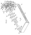
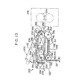
- the illustrated paper guiding device shown generally at 202 includes a lower guide plate 204 and an upper guide plate 206. It is easily understood from Figures 8 and 10 that the lower guide plate 204 in the illustrated embodiment has a main flat portion 208, a curved portion 210 following the downstream end (the left end .in Figure 10) of the main flat. portion 208, and an upstanding portion 212 extending downwardly from the curved portion 210. A downwardly extending hanging portion 214 is formed integrally at each side edge of the main flat portion 208.
- the lower guide plate 204 is fixed in position to the housing of a copying machine by keying the hanging portion 214 by means of a setscrew 218 to the inner surface of each of a pair of upstanding partitioning plates 216 disposed laterally in spaced-apart relationship within the housing of the copying machine (the partitioning plates 216 may be the same as the upstanding plates 90 shown in Figure 3), as shown in Figure 11.
- the partitioning plates 216 may be the same as the upstanding plates 90 shown in Figure 3
- elongaged oblique groove-like notches 224 are respectively formed which extend respectively from the upper edges of the side plates 220 in the upstream direction downwardly and inclinedly.
- Inwardly projecting pins 226 are firmly set respectively at the downstream ends portions (i.e.; the left end portions in Figure 10) of the side plates 220.
- the upper guide plate 206 has a main flat portion 228, and at the opposite side edges of the main flat portion 228, there are respectively formed as an integral unit side plates 230 which extend downwardly therefrom substantially perpendicularly.
- Outwardly projecting pins 232 are firmly set respectively at the upstream end portions (i.e., the right end portions in Figure 10) of the side plates 230.
- the downstream ends (i.e., the left end portions in Figure 10) of the side plates 230 have respectively formed therein groove-like notches 234 which extend upwardly from the lower edges of the side plates 230.
- Grip portions 236 projecting in the . downstream directions are also respectively formed in the downstream ends of the side plates 230.
- the upper guide plate 206 described above can be detachably mounted in position on the lower guide plate 204 by operating the aforesaid grip portions 236 so as to position the upper guide plates 206 above the lower guide plate 204 with its side plates 230 being interposed between the side plates 220 of the lower guide plate 204, then moving the upstream end portions of the side plates 230 downwardly in the upstream direction to insert the pins 232 in the notches 224 formed in the upstream end portions of the side plates 220 of the lower guide plate 204, and thereafter moving the downstream end portions of the side plates 230 downwardly to bring the notches 234 into engagement with the pins 226 firmly set at the downstream end portions of the side plates 220 of the lower guide plate 204.
- a plurality of rising pieces 238 should be provided laterally in spaced-apart relationship on the upper side of the main flat portion 208 of the lower guide plate 204, said rising pieces extending upwardly from the upper side of the main flat portion 208 in the moving direction of a copying paper (to the left and right in Figure 10), and that corresponding to these rising pieces, the lower side of the main flat portion 228 of the upper guide plate 206 should have formed thereon a plurality of hanging pieces 240 which are disposed laterally in spaced-apart relationship and extend downwardly from the lower side of the main flat portion 228 in the moving direction of the copying paper.
- each rising piece 238 is provided laterally at suitable intervals on the upper side of the main flat portion 208 of the lower guide plate 204.
- the rising pieces 238 are fixed in position to the upper side of the main flat portion 208 by, for example, bonding the base portions of these rising pieces to the upper side of the main flat portion 208.
- the rising pieces 238 extend upwardly from the upper side of the main flat portion 208 substantially perpendicularly over a predetermined range in the moving direction of the copying paper (i.e., to the right and left in Figure 10).
- eight hanging pieces 240 are disposed laterally at suitable intervals on the lower side of the main flat portion 228 of the upper guide plate 206.
- the hanging pieces 240 are fixed in position to the lower side of the main flat portion 228 by, for example, bonding their base portions to the lower side of the main flat portion 228. These hanging pieces 240 extend downwardly from the underside of the main flat portion 228 substantially perpendicularly over a predetermined range in the moving direction of the copying paper (i.e., to the left and right in Figure 10). As Figures 10 and 11 clearly show, the rising pieces 238 and the hanging pieces 240 cooperate with each other to define a paper moving passage therebetween.
- the upper edges of the rising pieces 238 cooperate with the lower edges of the hanging pieces 240 to define a path of paper movement therebetween; and a paper 242 (see Figures 8 and 1 0) moving through the paper guiding device 202 is guided by the upper edges of the rising pieces 238 and the lower edges of the hanging pieces 240.
- the upstream end portions (i.e., the right end portions in Figure 10) of the upper edges of the rising pieces 238 are inclined downwardly in the upstream direction, and the upstream end portions of the lower edges of the hanging pieces 240 are inclined upwardly in the upstream direction, so that the copying paper 242 (see Figures 8 and 10) advancing between the upper edges of the rising pieces 238 and the lower edges of the hanging pieces 240 is surely and easily guided by these rising and hanging pieces.
- the rising pieces 238 are formed separately from the main flat portion 208 of the lower guide plate 204 and fixed to the upper side of the main flat portion 208, and the hanging'pieces 240 are likewise formed separately from the main flat portion 228 of the upper guide plate 206 and fixed to the lower side of the main flat portion 228, it is possible, if desired, to form the rising pieces 238 integrally with the main flat portion 208 as a unit and to form the hanging pieces 240 integrally with the main flat portion 228 as a unit.
- openings 244 should be formed in the main flat portion 228 of the upper guide plate 206.
- eight rectangular openings 244 in total are formed in the main flat portion 228 of the upper guide plate 206 between the hanging pieces 240 and between the hanging pieces 240 end the side plates 230.
- these openings 244 are as large as possible so long as they do not affect the rigidity and strength of the upper guide plate 206, the bonding of the hanging pieces 240 to the lower side of the main flat portion 228, etc.
- a rectangular opening 246 be formed in each of the hanging pieces 240 themselves. Such openings 246 are also preferably as large as'possible so long as they do not affect the rigidity and strength of the hanging pieces 240, etc.
- the paper guiding device 202 shown in the drawings further comprises a delivery roller unit 248 disposed upstream (on the right in Figure 10) of the paper moving passage defined by the upper edges of the rising pieces 238 and the lower edges of the hanging pieces 240, and a discharge roller unit 250 disposed downstream (on the left in Figure 10) of the paper moving passage, as shown clearly in Figure 10.
- the delivery roller unit 248 is comprised of a plurality (5 in the drawing) of driven rollers 254 mounted on a driven shaft 252 at suitable intervals in the lateral direction and a plurality (5 in the drawing) of follower rollers 258 mounted on a follower shaft 256 correspondingly to the driven rollers 254.
- the discharge roller unit 250 is comprised of a plurality (3 in the drawing) of driven rollers 262 mounted on a driven shaft 260 at suitable intervals in the lateral direction and a plurality (3 in the drawing) of follower rollers 266 mounted on a follower shaft 264 correspondingly to the driven rollers 262.
- the driven shaft 260 of the discharge roller unit 250 is positioned below the curved portion 210 of the lower guide'plate 204, but as can be easily understood from Figure 8, the driven rollers 262 mounted on the driven shaft 260 project upwardly through cuts formed in the curved portion 210.
- the driven shaft 252 of the delivery roller unit 248 and the driven shaft 260 of the discharge roller unit 250 are rotatably supported on the pair of upstanding partitioning plates 216 ( Figure 11) disposed within the housing of the copying machine.
- the follower shaft 256 of the delivery roller unit 248 and the follower shaft 264 of the discharge roller unit 250 are respectively inserted rotatably for free up-and-down movement in narrow slots 268 and 270 extending in the up-and-down direction and formed on the side plates 230 disposed on the opposite side edges of the upper guide plate 206.
- the follower shaft 256 of the delivery roller unit 248 and the follower rollers 258 mounted on it and the follower shaft 264 of the discharge roller unit 250 and the follower rollers 266 mounted on it are biased downwardly by their own weights.
- the follower rollers 258 of the delivery roller unit 248 are brought into abutment against the driven rollers 254, and the follower rollers 266 of the discharge roller unit 250 are brought into abutment against the driven rollers 262.
- the follower shaft 256 of the delivery roller unit 248 and the follower shaft 264 of the discharge roller unit 250 may be resiliently biassed downwardly by suitable spring members (not shown).
- the driven shaft 252 and the driven shaft 260 are drivingly connected to a suitable driving source (not shown) such as an electric motor through a suitable power transmission means (not shown), and the delivery roller unit 248 and the discharge roller unit 250 are rotated in the direction of an arrow in Figure 10 by the action of the driving source.
- a suitable driving source such as an electric motor
- a suitable power transmission means not shown
- a charge-eliminating brush member 272 known per se is fastened by means cf a setscrew 274 to the downstream end (i.e., the left end in Figure 10) of the upper guide plate 206.
- the lower end of the charge-eliminating brush member 272 contacts or approaches the surface of the paper 242 ( Figures 8 and 10) discharged from the paper guiding device 202 by the action of the discharge roller unit 250, thereby to remove the residual charge from the paper 242.
- the paper guiding device 202 is suitably used for guiding the paper 242 ( Figures 8 and 10) discharged from a heat-fixing device 276 and conducting it to outside the housing of the copying machine, although its function is not limited to this feature.
- the paper guiding device 202 is provided adjacent to, and downstream of, a heat-fixing device 276 ( Figure 10).
- the heat-fixing device 276 ( Figure 10), for example, includes a pair of heat-fixing rollers 278 ( Figures 8 and 10) at least one of which is adapted to be heated by a suitable heat source (not shown) such as an electric resistance heating wire provided in its interior.
- the copying paper 242 is slightly pressed to fix the toner image formed on the paper.
- the paper 242 discharged from the heat-fixing device 276 by the feeding action of the heat-fixing rollers 278 rotated in the direction of an arrow in Figure 10 is nipped by the delivery roller unit 248 of the paper guiding device 202 and sent to the paper guiding device 202 by the delivering action of the delivery roller unit 248. Then, the paper 242 is moved through the paper moving passage defined by the upper edges of the rising pieces 238 and the lower edges of the hanging pieces 240.
- the paper 242 is carried away from the paper guiding device 202 by the discharging action of the discharge roller unit 250, and then discharged into a receiving tray (not shown) outside the housing of the copying machine through a discharge opening (not shown) formed on the end'wall of the housing.
- the paper 242. is heated to a considerably high temperature by the heating action of the pair of heat-fixing rollers 278, and therefore, the paper 242 to be introduced into the paper guiding device 202 is at a considerably high temperature.
- the paper 242 at such a high temperature enters the space between the lower guide plate 204 and the upper guide plate 206 of the paper guiding device 202, the space is heated by the heat dissipated from the paper 242. Since the outside of the paper guiding device 202 is generally kept at room temperature or a temperature close to it, moisture (dew) tends to form on the upper side of the main flat portion 208 of the lower guide plate 204, the lower side of the main flat portion 228 of the upper guide plate 206, etc.
- the openings 244 are formed in the main flat portion 228 and the openings 246 are also formed in the hanging pieces 240, the heat dissipated from the paper 242 passed between the lower guide plate 204 and the upper guide plate 206 is effectively dissipated out of the paper guiding device 202 through these openings 246 and 244, and consequently, the moisture formation on the upper surface of the main flat portion 208, the under surface of the main flat portion 228, etc. can be effectively prevented.
- the aforesaid relatively large drops of moisture do not form on the underside of the main flat portion 228 or on the hanging pieces 240 because openings are formed both on the main flat portion 228 and on the hanging pieces 240 to greatly reduce the heat capacity of the main flat portion 228 and the hanging pieces 240 and the actual areas of the underside of the main flat portion 228 and the side surfaces of the hanging pieces 240 on which dew could form are markedly decreased.
- openings may also be provided in the main flat portion 208 of the lower guide plate 204 and/or the rising pieces 238 to dissipate the heat more effectively from the space between the lower guide plate 204 and the upper guide plate 206 to outside the paper guiding device 202 and thus to further reduce the likelihood of dew formation on the upper side of the main flat portion 208 of the lower guide plate 204 and/or the side surfaces of the rising pieces 238.
Landscapes
- Engineering & Computer Science (AREA)
- Mechanical Engineering (AREA)
- Physics & Mathematics (AREA)
- General Physics & Mathematics (AREA)
- Sheets, Magazines, And Separation Thereof (AREA)
- Feeding Of Articles By Means Other Than Belts Or Rollers (AREA)
- Paper Feeding For Electrophotography (AREA)
Priority Applications (1)
| Application Number | Priority Date | Filing Date | Title |
|---|---|---|---|
| DE8585107953T DE3279232D1 (en) | 1981-03-02 | 1982-03-01 | Guiding device in a copying apparatus |
Applications Claiming Priority (6)
| Application Number | Priority Date | Filing Date | Title |
|---|---|---|---|
| JP28445/81 | 1981-03-02 | ||
| JP2844581A JPS57145735A (en) | 1981-03-02 | 1981-03-02 | Feeder with forcibly restraining mechanism |
| JP32265/81U | 1981-03-10 | ||
| JP3226581U JPS6326360Y2 (fr) | 1981-03-10 | 1981-03-10 | |
| JP1981032266U JPH0345233Y2 (fr) | 1981-03-10 | 1981-03-10 | |
| JP32266/81U | 1981-03-10 |
Related Child Applications (1)
| Application Number | Title | Priority Date | Filing Date |
|---|---|---|---|
| EP85107953.3 Division-Into | 1985-06-27 |
Publications (3)
| Publication Number | Publication Date |
|---|---|
| EP0059631A2 true EP0059631A2 (fr) | 1982-09-08 |
| EP0059631A3 EP0059631A3 (en) | 1983-05-18 |
| EP0059631B1 EP0059631B1 (fr) | 1986-08-20 |
Family
ID=27286203
Family Applications (1)
| Application Number | Title | Priority Date | Filing Date |
|---|---|---|---|
| EP82301022A Expired EP0059631B1 (fr) | 1981-03-02 | 1982-03-01 | Dispositif pour alimenter et guider des papiers dans une machine à copier |
Country Status (3)
| Country | Link |
|---|---|
| US (2) | US4523754A (fr) |
| EP (1) | EP0059631B1 (fr) |
| DE (1) | DE3272661D1 (fr) |
Cited By (6)
| Publication number | Priority date | Publication date | Assignee | Title |
|---|---|---|---|---|
| EP0103842A2 (fr) * | 1982-09-17 | 1984-03-28 | Siemens Aktiengesellschaft | Dispositif d'enlèvement sélectif de feuilles individielles de deux cassettes |
| DE3605887A1 (de) * | 1985-02-25 | 1986-09-04 | Sharp K.K., Osaka | Kopiergeraet mit mehreren aufnahmepositionen fuer kopierpapierkassetten |
| DE3622972A1 (de) * | 1985-07-11 | 1987-01-22 | Toshiba Kawasaki Kk | Abbildungsgeraet |
| EP0230313A2 (fr) * | 1986-01-22 | 1987-07-29 | Mita Industrial Co. Ltd. | Moyens de guidage de papier dans un appareil de formation d'image |
| US4708456A (en) * | 1984-02-18 | 1987-11-24 | Mita Industrial Co., Ltd. | Method and apparatus for feeding and conveying copying papers in a copying machine |
| EP0571006A1 (fr) * | 1992-03-24 | 1993-11-24 | Kodak Limited | Appareil de guidage |
Families Citing this family (20)
| Publication number | Priority date | Publication date | Assignee | Title |
|---|---|---|---|---|
| NL8402940A (nl) * | 1984-09-27 | 1986-04-16 | Oce Nederland Bv | Transportsysteem. |
| US4625955A (en) * | 1985-01-16 | 1986-12-02 | Donald L. Snellman | Sheet feeder |
| US4734738A (en) * | 1985-04-28 | 1988-03-29 | Mita Industrial Co., Ltd. | Copying apparatus |
| US4641949A (en) * | 1985-08-26 | 1987-02-10 | Xerox Corporation | Conductive brush paper position sensor |
| US5278623A (en) * | 1989-06-21 | 1994-01-11 | Konica Corporation | Image forming apparatus |
| JP2660181B2 (ja) * | 1991-04-09 | 1997-10-08 | 富士写真フイルム株式会社 | シート材の自動供給装置 |
| US5194904A (en) * | 1992-04-15 | 1993-03-16 | Compaq Computer Corporation | Exiting paper deflector apparatus for an image reproduction machine |
| AU656065B2 (en) * | 1992-04-15 | 1995-01-19 | Compaq Computer Corporation | Exiting paper deflector apparatus for an image reproduction machine |
| JP2966271B2 (ja) * | 1993-12-30 | 1999-10-25 | キヤノン株式会社 | 自動給紙装置および記録装置 |
| DE19601256C1 (de) * | 1996-01-16 | 1997-04-10 | Aeg Electrocom Gmbh | Vorrichtung zum Führen bewegter Sendungen |
| KR100224601B1 (ko) * | 1997-05-13 | 1999-10-15 | 윤종용 | 복합기의 자동 급지장치 |
| US6241237B1 (en) * | 1999-09-27 | 2001-06-05 | Hewlett-Packard Company | Automatic document feeding method and apparatus and duplexing document scanning device using same |
| US7007949B2 (en) * | 2003-07-17 | 2006-03-07 | Eastman Kodak Company | Multiple supply film transport mechanism |
| JP2010191056A (ja) * | 2009-02-17 | 2010-09-02 | Fuji Xerox Co Ltd | 画像形成装置 |
| US20110187041A1 (en) * | 2010-01-29 | 2011-08-04 | Foxlink Image Technology Co., Ltd. | Sheet processing apparatus |
| JP5644550B2 (ja) * | 2011-01-28 | 2014-12-24 | 村田機械株式会社 | 画像形成装置 |
| JP2014034432A (ja) * | 2012-08-07 | 2014-02-24 | Toshiba Corp | 画像形成装置 |
| EP2993149B1 (fr) * | 2014-07-28 | 2017-09-13 | OCE-Technologies B.V. | Unité de décharge de supports d'impression, et ensemble de guidage de supports d'impression, dispositif d'empilage de feuilles, appareil de reproduction d'image, et procédé pour modifier un appareil de reproduction d'image correspondantes |
| JP6701855B2 (ja) * | 2016-03-22 | 2020-05-27 | コニカミノルタ株式会社 | 画像形成装置 |
| JP7537954B2 (ja) * | 2020-09-02 | 2024-08-21 | シャープ株式会社 | 原稿送り装置および画像形成装置 |
Citations (2)
| Publication number | Priority date | Publication date | Assignee | Title |
|---|---|---|---|---|
| EP0001128A1 (fr) * | 1977-09-14 | 1979-03-21 | Konica Corporation | Machine à copier électrophotographique |
| US4155545A (en) * | 1976-12-14 | 1979-05-22 | Ricoh Co., Ltd. | Sheet feed apparatus for electrostatic copying machine or the like |
Family Cites Families (9)
| Publication number | Priority date | Publication date | Assignee | Title |
|---|---|---|---|---|
| US1225743A (en) * | 1909-06-24 | 1917-05-15 | Cottrell C B & Sons Co | Sheet-delivery apparatus for printing-machines. |
| US3804512A (en) * | 1971-06-03 | 1974-04-16 | Canon Kk | Copying apparatus for sheet originals and thicker originals |
| US3849907A (en) * | 1973-12-04 | 1974-11-26 | Xerox Corp | Fusing apparatus |
| US3914097A (en) * | 1974-02-01 | 1975-10-21 | Eastman Kodak Co | Sheet guide and cooling apparatus |
| US4134671A (en) * | 1977-03-25 | 1979-01-16 | Xerox Corporation | Intersecting optical and copy sheet path method and apparatus |
| JPS5442126A (en) * | 1977-09-09 | 1979-04-03 | Canon Inc | Exposure scanning device |
| JPS5738443A (en) * | 1980-08-20 | 1982-03-03 | Konishiroku Photo Ind Co Ltd | Drive controlling method of electrophotographic copier |
| US4372668A (en) * | 1980-12-24 | 1983-02-08 | Xerox Corporation | Sheet registration actuation |
| JPS5826747A (ja) * | 1982-06-10 | 1983-02-17 | Canon Inc | シ−ト案内装置 |
-
1982
- 1982-03-01 DE DE8282301022T patent/DE3272661D1/de not_active Expired
- 1982-03-01 EP EP82301022A patent/EP0059631B1/fr not_active Expired
-
1983
- 1983-11-23 US US06/554,644 patent/US4523754A/en not_active Expired - Fee Related
-
1985
- 1985-01-14 US US06/691,372 patent/US4879578A/en not_active Expired - Fee Related
Patent Citations (2)
| Publication number | Priority date | Publication date | Assignee | Title |
|---|---|---|---|---|
| US4155545A (en) * | 1976-12-14 | 1979-05-22 | Ricoh Co., Ltd. | Sheet feed apparatus for electrostatic copying machine or the like |
| EP0001128A1 (fr) * | 1977-09-14 | 1979-03-21 | Konica Corporation | Machine à copier électrophotographique |
Cited By (8)
| Publication number | Priority date | Publication date | Assignee | Title |
|---|---|---|---|---|
| EP0103842A2 (fr) * | 1982-09-17 | 1984-03-28 | Siemens Aktiengesellschaft | Dispositif d'enlèvement sélectif de feuilles individielles de deux cassettes |
| EP0103842A3 (fr) * | 1982-09-17 | 1985-11-27 | Siemens Aktiengesellschaft | Dispositif d'enlèvement sélectif de feuilles individielles de deux cassettes |
| US4708456A (en) * | 1984-02-18 | 1987-11-24 | Mita Industrial Co., Ltd. | Method and apparatus for feeding and conveying copying papers in a copying machine |
| DE3605887A1 (de) * | 1985-02-25 | 1986-09-04 | Sharp K.K., Osaka | Kopiergeraet mit mehreren aufnahmepositionen fuer kopierpapierkassetten |
| DE3622972A1 (de) * | 1985-07-11 | 1987-01-22 | Toshiba Kawasaki Kk | Abbildungsgeraet |
| EP0230313A2 (fr) * | 1986-01-22 | 1987-07-29 | Mita Industrial Co. Ltd. | Moyens de guidage de papier dans un appareil de formation d'image |
| EP0230313A3 (fr) * | 1986-01-22 | 1989-05-31 | Mita Industrial Co. Ltd. | Moyens de guidage de papier dans un appareil de formation d'image |
| EP0571006A1 (fr) * | 1992-03-24 | 1993-11-24 | Kodak Limited | Appareil de guidage |
Also Published As
| Publication number | Publication date |
|---|---|
| DE3272661D1 (en) | 1986-09-25 |
| EP0059631A3 (en) | 1983-05-18 |
| US4523754A (en) | 1985-06-18 |
| US4879578A (en) | 1989-11-07 |
| EP0059631B1 (fr) | 1986-08-20 |
Similar Documents
| Publication | Publication Date | Title |
|---|---|---|
| EP0059631A2 (fr) | Dispositif pour alimenter et guider des papiers dans une machine à copier | |
| US4556209A (en) | Sheet feeding apparatus | |
| US4645192A (en) | Sheet feeder | |
| JPH02100939A (ja) | 自動原稿搬送装置 | |
| US4523752A (en) | Original document inserting device for copying apparatus | |
| JPH028124A (ja) | 原稿給送装置 | |
| US4722518A (en) | Sheet feeder | |
| EP0918029B1 (fr) | Dispositif pour aligner des feuilles de papier | |
| JPH0658550B2 (ja) | 画像形成装置 | |
| US5028046A (en) | Feed path selection mechanism for sheets of paper capable of being driven by the existing drive system of a photocopier or the like | |
| US4240730A (en) | Unique gear drive mechanism for camera-processor | |
| JPS61111239A (ja) | 用紙給紙装置 | |
| JP2543595B2 (ja) | 画像形成装置 | |
| JPH0663551B2 (ja) | 自動原稿搬送装置の駆動装置 | |
| JPH0577951A (ja) | 給紙装置 | |
| JPH0549570B2 (fr) | ||
| JP2849909B2 (ja) | 自動原稿送り装置 | |
| JPS58172137A (ja) | 紙葉離の分類給送装置 | |
| JPH0416446A (ja) | 画像形成装置のシート搬入装置 | |
| JP2667513B2 (ja) | 用紙クランプ装置 | |
| JP2000103525A (ja) | 給紙装置 | |
| JPH03192075A (ja) | 画像記録装置の記録用紙搬送装置 | |
| JPH0930673A (ja) | 給紙装置 | |
| KR920005077Y1 (ko) | 복사기의 레지스터부 구동식 클러치장치 | |
| JP3040640B2 (ja) | シート材給送装置 |
Legal Events
| Date | Code | Title | Description |
|---|---|---|---|
| PUAI | Public reference made under article 153(3) epc to a published international application that has entered the european phase |
Free format text: ORIGINAL CODE: 0009012 |
|
| 17P | Request for examination filed |
Effective date: 19820308 |
|
| AK | Designated contracting states |
Designated state(s): DE FR GB NL |
|
| PUAL | Search report despatched |
Free format text: ORIGINAL CODE: 0009013 |
|
| AK | Designated contracting states |
Designated state(s): DE FR GB NL |
|
| GRAA | (expected) grant |
Free format text: ORIGINAL CODE: 0009210 |
|
| AK | Designated contracting states |
Kind code of ref document: B1 Designated state(s): DE FR GB NL |
|
| REF | Corresponds to: |
Ref document number: 3272661 Country of ref document: DE Date of ref document: 19860925 |
|
| ET | Fr: translation filed | ||
| PLBE | No opposition filed within time limit |
Free format text: ORIGINAL CODE: 0009261 |
|
| STAA | Information on the status of an ep patent application or granted ep patent |
Free format text: STATUS: NO OPPOSITION FILED WITHIN TIME LIMIT |
|
| 26N | No opposition filed | ||
| PGFP | Annual fee paid to national office [announced via postgrant information from national office to epo] |
Ref country code: GB Payment date: 19950220 Year of fee payment: 14 |
|
| PGFP | Annual fee paid to national office [announced via postgrant information from national office to epo] |
Ref country code: DE Payment date: 19950222 Year of fee payment: 14 |
|
| PGFP | Annual fee paid to national office [announced via postgrant information from national office to epo] |
Ref country code: FR Payment date: 19950309 Year of fee payment: 14 |
|
| PGFP | Annual fee paid to national office [announced via postgrant information from national office to epo] |
Ref country code: NL Payment date: 19950331 Year of fee payment: 14 |
|
| PG25 | Lapsed in a contracting state [announced via postgrant information from national office to epo] |
Ref country code: GB Effective date: 19960301 |
|
| PG25 | Lapsed in a contracting state [announced via postgrant information from national office to epo] |
Ref country code: NL Effective date: 19961001 |
|
| GBPC | Gb: european patent ceased through non-payment of renewal fee |
Effective date: 19960301 |
|
| PG25 | Lapsed in a contracting state [announced via postgrant information from national office to epo] |
Ref country code: FR Effective date: 19961129 |
|
| NLV4 | Nl: lapsed or anulled due to non-payment of the annual fee |
Effective date: 19961001 |
|
| PG25 | Lapsed in a contracting state [announced via postgrant information from national office to epo] |
Ref country code: DE Effective date: 19961203 |
|
| REG | Reference to a national code |
Ref country code: FR Ref legal event code: ST |