EP0055211B1 - Siegelbackenanordnung - Google Patents
Siegelbackenanordnung Download PDFInfo
- Publication number
- EP0055211B1 EP0055211B1 EP81810427A EP81810427A EP0055211B1 EP 0055211 B1 EP0055211 B1 EP 0055211B1 EP 81810427 A EP81810427 A EP 81810427A EP 81810427 A EP81810427 A EP 81810427A EP 0055211 B1 EP0055211 B1 EP 0055211B1
- Authority
- EP
- European Patent Office
- Prior art keywords
- arrangement
- sealing jaws
- pair
- parallel
- disposed
- Prior art date
- Legal status (The legal status is an assumption and is not a legal conclusion. Google has not performed a legal analysis and makes no representation as to the accuracy of the status listed.)
- Expired
Links
Images

Classifications
-
- B—PERFORMING OPERATIONS; TRANSPORTING
- B29—WORKING OF PLASTICS; WORKING OF SUBSTANCES IN A PLASTIC STATE IN GENERAL
- B29C—SHAPING OR JOINING OF PLASTICS; SHAPING OF MATERIAL IN A PLASTIC STATE, NOT OTHERWISE PROVIDED FOR; AFTER-TREATMENT OF THE SHAPED PRODUCTS, e.g. REPAIRING
- B29C65/00—Joining or sealing of preformed parts, e.g. welding of plastics materials; Apparatus therefor
- B29C65/02—Joining or sealing of preformed parts, e.g. welding of plastics materials; Apparatus therefor by heating, with or without pressure
- B29C65/18—Joining or sealing of preformed parts, e.g. welding of plastics materials; Apparatus therefor by heating, with or without pressure using heated tools
-
- B—PERFORMING OPERATIONS; TRANSPORTING
- B29—WORKING OF PLASTICS; WORKING OF SUBSTANCES IN A PLASTIC STATE IN GENERAL
- B29C—SHAPING OR JOINING OF PLASTICS; SHAPING OF MATERIAL IN A PLASTIC STATE, NOT OTHERWISE PROVIDED FOR; AFTER-TREATMENT OF THE SHAPED PRODUCTS, e.g. REPAIRING
- B29C65/00—Joining or sealing of preformed parts, e.g. welding of plastics materials; Apparatus therefor
- B29C65/74—Joining or sealing of preformed parts, e.g. welding of plastics materials; Apparatus therefor by welding and severing, or by joining and severing, the severing being performed in the area to be joined, next to the area to be joined, in the joint area or next to the joint area
- B29C65/745—Joining or sealing of preformed parts, e.g. welding of plastics materials; Apparatus therefor by welding and severing, or by joining and severing, the severing being performed in the area to be joined, next to the area to be joined, in the joint area or next to the joint area using a single unit having both a severing tool and a welding tool
-
- B—PERFORMING OPERATIONS; TRANSPORTING
- B29—WORKING OF PLASTICS; WORKING OF SUBSTANCES IN A PLASTIC STATE IN GENERAL
- B29C—SHAPING OR JOINING OF PLASTICS; SHAPING OF MATERIAL IN A PLASTIC STATE, NOT OTHERWISE PROVIDED FOR; AFTER-TREATMENT OF THE SHAPED PRODUCTS, e.g. REPAIRING
- B29C66/00—General aspects of processes or apparatus for joining preformed parts
- B29C66/01—General aspects dealing with the joint area or with the area to be joined
- B29C66/05—Particular design of joint configurations
- B29C66/10—Particular design of joint configurations particular design of the joint cross-sections
- B29C66/11—Joint cross-sections comprising a single joint-segment, i.e. one of the parts to be joined comprising a single joint-segment in the joint cross-section
- B29C66/112—Single lapped joints
- B29C66/1122—Single lap to lap joints, i.e. overlap joints
-
- B—PERFORMING OPERATIONS; TRANSPORTING
- B29—WORKING OF PLASTICS; WORKING OF SUBSTANCES IN A PLASTIC STATE IN GENERAL
- B29C—SHAPING OR JOINING OF PLASTICS; SHAPING OF MATERIAL IN A PLASTIC STATE, NOT OTHERWISE PROVIDED FOR; AFTER-TREATMENT OF THE SHAPED PRODUCTS, e.g. REPAIRING
- B29C66/00—General aspects of processes or apparatus for joining preformed parts
- B29C66/01—General aspects dealing with the joint area or with the area to be joined
- B29C66/345—Progressively making the joint, e.g. starting from the middle
- B29C66/3452—Making complete joints by combining partial joints
-
- B—PERFORMING OPERATIONS; TRANSPORTING
- B29—WORKING OF PLASTICS; WORKING OF SUBSTANCES IN A PLASTIC STATE IN GENERAL
- B29C—SHAPING OR JOINING OF PLASTICS; SHAPING OF MATERIAL IN A PLASTIC STATE, NOT OTHERWISE PROVIDED FOR; AFTER-TREATMENT OF THE SHAPED PRODUCTS, e.g. REPAIRING
- B29C66/00—General aspects of processes or apparatus for joining preformed parts
- B29C66/40—General aspects of joining substantially flat articles, e.g. plates, sheets or web-like materials; Making flat seams in tubular or hollow articles; Joining single elements to substantially flat surfaces
- B29C66/41—Joining substantially flat articles ; Making flat seams in tubular or hollow articles
- B29C66/43—Joining a relatively small portion of the surface of said articles
- B29C66/431—Joining the articles to themselves
- B29C66/4312—Joining the articles to themselves for making flat seams in tubular or hollow articles, e.g. transversal seams
-
- B—PERFORMING OPERATIONS; TRANSPORTING
- B29—WORKING OF PLASTICS; WORKING OF SUBSTANCES IN A PLASTIC STATE IN GENERAL
- B29C—SHAPING OR JOINING OF PLASTICS; SHAPING OF MATERIAL IN A PLASTIC STATE, NOT OTHERWISE PROVIDED FOR; AFTER-TREATMENT OF THE SHAPED PRODUCTS, e.g. REPAIRING
- B29C66/00—General aspects of processes or apparatus for joining preformed parts
- B29C66/80—General aspects of machine operations or constructions and parts thereof
- B29C66/81—General aspects of the pressing elements, i.e. the elements applying pressure on the parts to be joined in the area to be joined, e.g. the welding jaws or clamps
- B29C66/814—General aspects of the pressing elements, i.e. the elements applying pressure on the parts to be joined in the area to be joined, e.g. the welding jaws or clamps characterised by the design of the pressing elements, e.g. of the welding jaws or clamps
- B29C66/8141—General aspects of the pressing elements, i.e. the elements applying pressure on the parts to be joined in the area to be joined, e.g. the welding jaws or clamps characterised by the design of the pressing elements, e.g. of the welding jaws or clamps characterised by the surface geometry of the part of the pressing elements, e.g. welding jaws or clamps, coming into contact with the parts to be joined
- B29C66/81411—General aspects of the pressing elements, i.e. the elements applying pressure on the parts to be joined in the area to be joined, e.g. the welding jaws or clamps characterised by the design of the pressing elements, e.g. of the welding jaws or clamps characterised by the surface geometry of the part of the pressing elements, e.g. welding jaws or clamps, coming into contact with the parts to be joined characterised by its cross-section, e.g. transversal or longitudinal, being non-flat
- B29C66/81421—General aspects of the pressing elements, i.e. the elements applying pressure on the parts to be joined in the area to be joined, e.g. the welding jaws or clamps characterised by the design of the pressing elements, e.g. of the welding jaws or clamps characterised by the surface geometry of the part of the pressing elements, e.g. welding jaws or clamps, coming into contact with the parts to be joined characterised by its cross-section, e.g. transversal or longitudinal, being non-flat being convex or concave
- B29C66/81422—General aspects of the pressing elements, i.e. the elements applying pressure on the parts to be joined in the area to be joined, e.g. the welding jaws or clamps characterised by the design of the pressing elements, e.g. of the welding jaws or clamps characterised by the surface geometry of the part of the pressing elements, e.g. welding jaws or clamps, coming into contact with the parts to be joined characterised by its cross-section, e.g. transversal or longitudinal, being non-flat being convex or concave being convex
-
- B—PERFORMING OPERATIONS; TRANSPORTING
- B29—WORKING OF PLASTICS; WORKING OF SUBSTANCES IN A PLASTIC STATE IN GENERAL
- B29C—SHAPING OR JOINING OF PLASTICS; SHAPING OF MATERIAL IN A PLASTIC STATE, NOT OTHERWISE PROVIDED FOR; AFTER-TREATMENT OF THE SHAPED PRODUCTS, e.g. REPAIRING
- B29C66/00—General aspects of processes or apparatus for joining preformed parts
- B29C66/80—General aspects of machine operations or constructions and parts thereof
- B29C66/81—General aspects of the pressing elements, i.e. the elements applying pressure on the parts to be joined in the area to be joined, e.g. the welding jaws or clamps
- B29C66/814—General aspects of the pressing elements, i.e. the elements applying pressure on the parts to be joined in the area to be joined, e.g. the welding jaws or clamps characterised by the design of the pressing elements, e.g. of the welding jaws or clamps
- B29C66/8141—General aspects of the pressing elements, i.e. the elements applying pressure on the parts to be joined in the area to be joined, e.g. the welding jaws or clamps characterised by the design of the pressing elements, e.g. of the welding jaws or clamps characterised by the surface geometry of the part of the pressing elements, e.g. welding jaws or clamps, coming into contact with the parts to be joined
- B29C66/81433—General aspects of the pressing elements, i.e. the elements applying pressure on the parts to be joined in the area to be joined, e.g. the welding jaws or clamps characterised by the design of the pressing elements, e.g. of the welding jaws or clamps characterised by the surface geometry of the part of the pressing elements, e.g. welding jaws or clamps, coming into contact with the parts to be joined being toothed, i.e. comprising several teeth or pins, or being patterned
- B29C66/81435—General aspects of the pressing elements, i.e. the elements applying pressure on the parts to be joined in the area to be joined, e.g. the welding jaws or clamps characterised by the design of the pressing elements, e.g. of the welding jaws or clamps characterised by the surface geometry of the part of the pressing elements, e.g. welding jaws or clamps, coming into contact with the parts to be joined being toothed, i.e. comprising several teeth or pins, or being patterned comprising several parallel ridges, e.g. for crimping
-
- B—PERFORMING OPERATIONS; TRANSPORTING
- B29—WORKING OF PLASTICS; WORKING OF SUBSTANCES IN A PLASTIC STATE IN GENERAL
- B29C—SHAPING OR JOINING OF PLASTICS; SHAPING OF MATERIAL IN A PLASTIC STATE, NOT OTHERWISE PROVIDED FOR; AFTER-TREATMENT OF THE SHAPED PRODUCTS, e.g. REPAIRING
- B29C66/00—General aspects of processes or apparatus for joining preformed parts
- B29C66/80—General aspects of machine operations or constructions and parts thereof
- B29C66/83—General aspects of machine operations or constructions and parts thereof characterised by the movement of the joining or pressing tools
- B29C66/834—General aspects of machine operations or constructions and parts thereof characterised by the movement of the joining or pressing tools moving with the parts to be joined
- B29C66/8351—Jaws mounted on rollers, cylinders, drums, bands, belts or chains; Flying jaws
- B29C66/83511—Jaws mounted on rollers, cylinders, drums, bands, belts or chains; Flying jaws jaws mounted on rollers, cylinders or drums
- B29C66/83513—Jaws mounted on rollers, cylinders, drums, bands, belts or chains; Flying jaws jaws mounted on rollers, cylinders or drums cooperating jaws mounted on rollers, cylinders or drums and moving in a closed path
-
- B—PERFORMING OPERATIONS; TRANSPORTING
- B29—WORKING OF PLASTICS; WORKING OF SUBSTANCES IN A PLASTIC STATE IN GENERAL
- B29C—SHAPING OR JOINING OF PLASTICS; SHAPING OF MATERIAL IN A PLASTIC STATE, NOT OTHERWISE PROVIDED FOR; AFTER-TREATMENT OF THE SHAPED PRODUCTS, e.g. REPAIRING
- B29C66/00—General aspects of processes or apparatus for joining preformed parts
- B29C66/80—General aspects of machine operations or constructions and parts thereof
- B29C66/84—Specific machine types or machines suitable for specific applications
- B29C66/849—Packaging machines
-
- B—PERFORMING OPERATIONS; TRANSPORTING
- B65—CONVEYING; PACKING; STORING; HANDLING THIN OR FILAMENTARY MATERIAL
- B65B—MACHINES, APPARATUS OR DEVICES FOR, OR METHODS OF, PACKAGING ARTICLES OR MATERIALS; UNPACKING
- B65B51/00—Devices for, or methods of, sealing or securing package folds or closures; Devices for gathering or twisting wrappers, or necks of bags
- B65B51/10—Applying or generating heat or pressure or combinations thereof
- B65B51/26—Devices specially adapted for producing transverse or longitudinal seams in webs or tubes
- B65B51/30—Devices, e.g. jaws, for applying pressure and heat, e.g. for subdividing filled tubes
- B65B51/306—Counter-rotating devices
Definitions
- the present invention relates to a sealing jaw arrangement in tubular bag packaging machines according to the preamble of claim 1.
- two embossing heads lie on rotatable rollers arranged opposite one another.
- Each embossing head has elevations and depressions in such a way that a waffle pattern is formed, of which the boundary lines represent the elevations.
- the upstream embossing head pairs 10a, 11 and 10b, 11b are each fixed on a roller 10 and 11 in a known manner and the two rollers rotate at the same rotational speed.
- the embossed edges 12 are arranged perpendicular to the axes of the rollers 10, 11 and are divided by grooves 13 parallel to the axes of the rollers.
- a further pair of rollers 20, 21 is arranged downstream, which also carries pairs of interacting embossing heads 20a, 21a and 20b, 21b.
- the embossing edges 22 of these embossing heads are arranged parallel to the axes of the rollers and there are also knife parts 24, 25 (FIG. 3) for separating closed bags in the middle between the embossing edges.
- a hose S is indicated upstream of the first pair of rollers and separated bags B are shown downstream.
- the rollers 10, 11 according to FIG. 2 each carry an embossing head, for. B. 10a, 11a.
- embossing edges 12 of the embossing head 10a mesh with embossing edges 14 of the embossing head 11a, so that there is always an elevation of one embossing head on the gap of the other embossing head.
- the grooves 13 can also be clearly seen.
- the embossing heads 20a, 21a of the rollers 20 and 21 have embossing edges 22 which run perpendicular to the plane of the drawing.
- the surveys are combing, in that one elevation of one of the embossing heads stands on the gap of the other embossing head.
- a pair of knives 24, 25 with tips and recesses according to known embodiments is arranged centrally in the embossing heads.
- the distance in both types of embossing heads between the elevations 41 standing on the gap 40 is greater than the distance measured perpendicular to the flanks 42, 43.
- sealing material either an adhesive or thermoplastic synthetic resin
- the axially parallel grooves 13 in the embossing heads 10a, b and 11a, b also serve the same purpose, because even in these areas I can collect excess adhesive, which is then distributed again during the second embossing with the embossing heads 20a, 20b and 21a, 21b , so that finally a gas-tight seal is obtained.
- embossing points arranged orthogonally to one another are provided. In one example, these are parallel or perpendicular arranged to the longitudinal axis of the hose and in the example of FIG. 6, these are rotated 45 ° to the longitudinal axis.
Description
- Die vorliegende Erfindung betrifft eine Siegelbackenanordnung bei Schlauchbeutel-Verpackungsmaschinen gemäss dem Gattungsbegriff des Anspruchs 1.
- Bei Schlauchbeutelverpackungen werden in gegenseitigem Abstand ankommende Gegenstände in Verpackungshüllen eingelegt und anschliessend werden die Hüllen durch Prägung verschlossen und versiegelt und die einzelnen Packungen voneinander abgetrennt. Die Siegelbackenanordnungen weisen einander gegenüberliegende Prägeköpfe auf, die am Maschinenrahmen rotierbar gelagert sind. Solche Prägeköpfe sind in der Verpackungstechnik gut bekannt.
- Gemäss einer Ausführungsform, die in der US-A-2 546 721 beschrieben ist, liegen zwei Prägeköpfe auf einander gegenüber angeordneten rotierbaren Walzen. Jeder Prägekopf hat Erhebungen und Vertiefungen, derart, dass ein Waffelmuster gebildet ist, von dem die Begrenzungslinien die Erhebungen darstellen. Bei schweren Materialien, bei mit Längsnähten gebildeten Schlauchbeutein oder bei Zwickelfaltungen hat sich gezeigt, dass ein derartiger Verschluss nur mit starker Verlangsamung der Maschine gasdicht herstellbar ist, und zwar muss die zeitliche Folge der Arbeitstakte auf die benötigte Wärmezufuhr abgestimmt werden.
- Es ist eine Aufgabe der Erfindung, eine Anordnung zu schaffen, mit der sich gasdichte Nähte herstellen lassen und zwar unabhängig von der Anzahl der Lagen des Verpackungsmaterials oder von dessen Dicke und bei gleichbleibender, oder wenn möglich, erhöhter Durchlaufgeschwindigkeit.
- Erfindungsgemäss wird dies durch die Merkmale des Anspruchs 1 erreicht.
- Ein Ausführungsbeispiel der Erfindung wird nachfolgend beschrieben. In der Zeichnung zeigen :
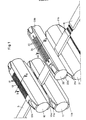
- Figur 1 eine perspektivische Darstellung von zwei hintereinander im Arbeitsweg einer Verpackungsmaschine angeordneten Siegelbakkenpaaren,
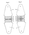
- Figur 2 eine Schnittansicht durch einen Teil des stromaufwärtigen Prägekopfes nach der Schnittlinie 11-11 in Fig. 1,
- Figur 3 eine Schnittansicht wie in Fig. 2, jedoch des stromabwärtigen Prägekopfes mit Messer, nach der Schnittlinie 111-111 in Fig. 1,
- Figur 4 in vergrössertem Massstab einen Schnitt durch kämmende Prägeköpfe senkrecht zu den Prägekanten, und
- Figur 5 und Figur 6 perspektivische Darstellungen von Verpackungen mit zwei Arten von Siegelnähten.
- Die Verpackungsmaschinen sind in der Verpackungsindustrie gut bekannt. Aus diesem Grund wurde auf die detaillierte Darstellung einer solchen verzichtet. Sie könnte gleich ausgebildet sein wie diegenigen im eingangs erwähnten US-Patent 2 546 721, bis auf die Partie mit den Prägeköpfen, die dementsprechend in der vorliegenden Fig. 1 deutlich dargestellt ist. Auch wurden die Heizungen und deren Anschlüsse weggelassen, ebenso die Mittel zur Lagerung und zur Rotation der Prägeköpfe.
- In Fig. 1 sind die stromaufwärtsgelegenen Prägekopfpaare 10a, 11 und 10b, 11 b je auf einer Walze 10 bzw. 11 in bekannter Weise befestigt und die beiden Walzen drehen mit gleicher Drehgeschwindigkeit. Die Prägekanten 12 sind senkrecht zu den Achsen der Walzen 10, 11 angeordnet und sind durch Nuten 13 parallel zu den Achsen der Walzen unterteilt.
- Stromabwärts ist ein weiteres Walzenpaar 20, 21 angeordnet, des ebenfalls Paare von zusammenwirkenden Prägeköpfen 20a, 21a und 20b, 21 b trägt. Die Prägekanten 22 dieser Prägeköpfe sind parallel zu den Achsen der Walzen angeordnet und es sind noch Messerteile 24, 25 (Fig. 3) zum Abtrennen von verschlossenen Beuteln in der Mitte zwischen den Prägekanten angeordnet.
- Ein Schlauch S ist stromaufwärts des ersten Walzenpaares angedeutet und abgetrennte Beutel B sind stromabwärts dargestellt.
- Fig. 2 und 3 zeigen Ausschnitte aus senkrecht zu den Walzenachsen verlaufenden Schnittebenen. Die Walzen 10, 11 gemäss Fig. 2 tragen je einen Prägekopf, z. B. 10a, 11a. Wie aus der Zeichnung deutlich hervorgeht, kämmen die Prägekanten 12 des Prägekopfes 10a mit Prägekanten 14 des Prägekopfes 11a, so dass immer eine Erhebung des einen Prägekopfes auf Lücke des andern Prägekopfes steht. Ebenfalls deutlich sind die Nuten 13 zu erkennen.
- Die Prägeköpfe 20a, 21a der Walzen 20 und 21 haben Prägekanten 22, die senkrecht zur Zeichnungsebene verlaufen. Auch hier kämmen die Erhebungen, indem eine Erhebung des einen Prägekopfes auf Lücke des andern Prägekopfes steht. Ein Messerpaar 24, 25 mit Spitzen und Ausnehmungen gemäss bekannter Ausführungsformen ist mittig in den Prägeköpfen angeordnet.
- Wie Fig. 4 zeigt, ist der Abstand bei beiden Arten von Prägeköpfen zwischen den auf Lücke 40 stehenden Erhebungen 41 grösser als der senkrecht auf den Flanken 42, 43 gemessene Abstand. Damit kann erreicht werden, dass Siegelmaterial, entweder ein Klebstoff oder thermoplastisches Kunstharz, aus der Partie zwischen den Flanken in die Partien zwischen Erhebungen und Lücken gepresst wird. Denselben Zweck erfüllen auch die achsparallelen Nuten 13 in den Prägeköpfen 10a, b und 11a, b, denn auch in diesen Bereichen kann ich überschüssiger Klebstoff ansammeln, der dann bei der zweiten Prägung mit den Prägeköpfen 20a, 20b und 21a, 21 b sich wieder verteilt, so dass schliesslich eine gasdichte Siegelung erhalten wird.
- Gemäss Fig. 5 und 6 sind orthogonal zueinander angeordnete Prägestellen vorgesehen. Beim einen Beispiel sind diese parallel bzw. senkrecht zur Längsachse des Schlauches angeordnet und im Beispiel nach Fig. 6 sind diese 45° zur Längsachse gedreht.
- Erstaunlicherweise hat sich herausgestellt, dass bei dickem Einschlagmaterial mit bekanntlich schlechter Wärmeleitfähigkeit sowie mit über 200 Umdrehungen der Walze pro Minute Schlauchbeutel gebildet wurden, bei denen auch an Stellen mit doppelten Folienlagen, wie bei Längsnähten oder bei Zwickeln, gasdichte Verschlüsse erhalten wurden.
Claims (11)
Applications Claiming Priority (2)
| Application Number | Priority Date | Filing Date | Title |
|---|---|---|---|
| CH9597/80 | 1980-12-24 | ||
| CH959780 | 1980-12-24 |
Publications (3)
| Publication Number | Publication Date |
|---|---|
| EP0055211A2 EP0055211A2 (de) | 1982-06-30 |
| EP0055211A3 EP0055211A3 (en) | 1982-10-06 |
| EP0055211B1 true EP0055211B1 (de) | 1984-09-05 |
Family
ID=4353630
Family Applications (1)
| Application Number | Title | Priority Date | Filing Date |
|---|---|---|---|
| EP81810427A Expired EP0055211B1 (de) | 1980-12-24 | 1981-10-27 | Siegelbackenanordnung |
Country Status (5)
| Country | Link |
|---|---|
| US (1) | US4455808A (de) |
| EP (1) | EP0055211B1 (de) |
| JP (1) | JPS57114426A (de) |
| BR (1) | BR8108166A (de) |
| DE (1) | DE3165863D1 (de) |
Cited By (1)
| Publication number | Priority date | Publication date | Assignee | Title |
|---|---|---|---|---|
| DE3815092A1 (de) * | 1988-05-04 | 1989-11-16 | Zeva Gmbh | Folienschweissvorrichtung |
Families Citing this family (38)
| Publication number | Priority date | Publication date | Assignee | Title |
|---|---|---|---|---|
| EP0130148A3 (de) * | 1983-06-24 | 1986-02-05 | SIG Schweizerische Industrie-Gesellschaft | Verfahren zur Herstellung einer Schlauchpackung und Vorrichtung zur Ausführung des Verfahrens sowie nach dem Verfahren hergestellte Packung |
| US4586317A (en) * | 1983-10-31 | 1986-05-06 | Kraft, Inc. | Minutely cross channeled voiding sealing systems |
| US4582555A (en) * | 1984-12-17 | 1986-04-15 | Crown Zellerbach Corporation | Heatseal die |
| JP2577549B2 (ja) * | 1986-09-11 | 1997-02-05 | エービー テトラパック | ゲーブルトップ型容器の頂部シール装置 |
| IT1208411B (it) * | 1987-04-28 | 1989-06-12 | Cavanna Spa | Gruppo a ganasce per macchine confe zionatrici particolarmente macchine confezionatrici di involucri tubolari del tipo flow pack e simili |
| DE3862511D1 (de) * | 1987-04-28 | 1991-05-29 | Sig Schweiz Industrieges | Siegelbacke fuer verpackungsmaschinen. |
| US4807426A (en) * | 1987-09-08 | 1989-02-28 | Smith Larry E | Crimper bar set for forming hermetically sealed packages |
| US4856259A (en) * | 1988-10-17 | 1989-08-15 | Baxter International Inc. | Appratus for sealing and severing a web of film |
| US5440860A (en) * | 1989-06-05 | 1995-08-15 | Schreiber Foods, Inc. | Method and apparatus for forming and hermetically sealing slices of food items |
| US5021117A (en) * | 1989-06-26 | 1991-06-04 | Zip-Pak, Inc. | Sealing jaw for heat sealable film with zippered section |
| US4949846A (en) * | 1989-07-31 | 1990-08-21 | Lakey Lawrence D | Package end sealing and cutting method and apparatus |
| JPH08564B2 (ja) * | 1989-08-31 | 1996-01-10 | 株式会社松澤製作所 | 熱可塑性樹脂シートのシール方法及び装置 |
| US5076040A (en) * | 1990-01-02 | 1991-12-31 | W.A. Lane, Inc. | Seal bars having asymmetric surface features |
| US5584166A (en) * | 1994-11-10 | 1996-12-17 | Lakey; Lawrence D. | Flexible package end sealing and cutting method and apparatus |
| US5727686A (en) * | 1995-07-31 | 1998-03-17 | Kristal; Boaz | Tamper-evident security envelopes |
| US6023917A (en) * | 1995-09-22 | 2000-02-15 | Sig Schweizerische Industrie-Gesellschaft | Method of producing finned packages, and a separating device for carrying out the method |
| US5868901A (en) | 1996-09-13 | 1999-02-09 | Lako Tool & Manufacturing, Inc. | Crimper assembly for sealing overlapping portions of a sheet of packaging material |
| US5934045A (en) * | 1996-12-04 | 1999-08-10 | Privatizer Systems, Inc. | Method for providing confidentiality to a facsimile transmission having information associated with a first page of the transmission printed on a first enclosure sheet |
| US5956930A (en) * | 1996-12-04 | 1999-09-28 | Privatizer Systems, Inc. | Apparatus and method of forming an envelope in a document security apparatus |
| US6076336A (en) * | 1996-12-04 | 2000-06-20 | Privatizer Systems, Inc. | Apparatus and method for advancing a confidential sheet into a pocket defined by a number of enclosure sheets |
| US5887411A (en) * | 1996-12-04 | 1999-03-30 | Privatizer Systems, Inc. | Apparatus and method for positioning a number of non-transparent enclosure sheets in a document security apparatus |
| US5946889A (en) * | 1996-12-04 | 1999-09-07 | Privatizer Systems, Inc | Apparatus and method for enclosing a confidential sheet between a first enclosure sheet and a second enclosure sheet within a document security apparatus |
| US5941048A (en) * | 1996-12-04 | 1999-08-24 | Privatizer Systems, Inc | Apparatus and method of sealing an envelope in a document security apparatus |
| US5996317A (en) * | 1996-12-04 | 1999-12-07 | Privatizer Systems, Inc. | Method for providing confidentiality to a facsimile transmission having a non-printed back enclosure sheet |
| US5937619A (en) * | 1996-12-04 | 1999-08-17 | Privatizer Systems Incorporated | Apparatus and method for sealing an envelope having a first lateral side and a second lateral side in a document security apparatus |
| US5979148A (en) * | 1996-12-04 | 1999-11-09 | Privatizer Systems, Inc. | Apparatus and method for sealing an envelope in a document security apparatus having a sealing roller with a sealing ridge attached thereto |
| US6041580A (en) * | 1998-07-29 | 2000-03-28 | Greener Corp. | Crimping jaw assemblies for forming package closures |
| ES2228783T3 (es) * | 2000-01-27 | 2005-04-16 | Sig Pack Systems Ag | Dispositivo para sellar empaquetados tubulares. |
| ITBO20030581A1 (it) * | 2003-10-09 | 2005-04-10 | Cmc Spa | Metodo e apparecchiatura per il confezionamento di articoli con un film di materiale plastico |
| SE527028C2 (sv) * | 2004-04-29 | 2005-12-06 | Tetra Laval Holdings & Finance | Mothåll och metod att framställa detta |
| JP4758676B2 (ja) * | 2005-05-12 | 2011-08-31 | オリヒロエンジニアリング株式会社 | 封止装置及びこれを用いた製袋充填包装機 |
| JP4824497B2 (ja) * | 2006-07-31 | 2011-11-30 | 大成ラミック株式会社 | 充填包装機 |
| JP5090942B2 (ja) * | 2007-02-22 | 2012-12-05 | 三光機械株式会社 | シールロール用ヒートシール刃の工夫 |
| EP2113371A1 (de) * | 2008-04-29 | 2009-11-04 | Tetra Laval Holdings & Finance SA | Schweißbacke zur Herstellung versiegelter Packungen eines Lebensmittelproduktes |
| JP5333038B2 (ja) * | 2008-09-10 | 2013-11-06 | パナソニック株式会社 | 真空断熱材とその製造方法 |
| ITMI20120286A1 (it) * | 2012-02-27 | 2013-08-28 | Sales Spa | Stazione di applicazione di segmenti di striscia di apertura/richiusura su film plastici in nastro atti a formare sacchetti |
| CN109476092A (zh) * | 2016-08-31 | 2019-03-15 | 惠普印迪格公司 | 密封工具及密封包装件 |
| WO2019211390A1 (en) | 2018-05-03 | 2019-11-07 | Esko-Graphics Kongsberg As | Heated tool for cutting and sealing meltable material |
Family Cites Families (7)
| Publication number | Priority date | Publication date | Assignee | Title |
|---|---|---|---|---|
| US2276083A (en) * | 1935-09-06 | 1942-03-10 | Carey Philip Mfg Co | Molded cement product and manufacture of same |
| US2362459A (en) * | 1942-02-07 | 1944-11-14 | Nat Urn Bag Co Inc | Infusion package and the manufacture thereof |
| US3243334A (en) * | 1963-03-01 | 1966-03-29 | Nat Distillers Chem Corp | Thermosealing device |
| JPS5338040B2 (de) * | 1974-08-27 | 1978-10-13 | ||
| US4106265A (en) * | 1975-05-29 | 1978-08-15 | Fmc Corporation | Wrapping machine and method with four side rotary tucker |
| US4102111A (en) * | 1976-06-01 | 1978-07-25 | Fmc Corporation | Wrapping machine |
| US4254601A (en) * | 1979-02-23 | 1981-03-10 | Keebler Company | Packaging machine having a slitter for forming slits in ends of packages |
-
1981
- 1981-10-27 EP EP81810427A patent/EP0055211B1/de not_active Expired
- 1981-10-27 DE DE8181810427T patent/DE3165863D1/de not_active Expired
- 1981-10-30 JP JP56173105A patent/JPS57114426A/ja active Pending
- 1981-12-16 BR BR8108166A patent/BR8108166A/pt unknown
- 1981-12-23 US US06/333,690 patent/US4455808A/en not_active Expired - Fee Related
Cited By (1)
| Publication number | Priority date | Publication date | Assignee | Title |
|---|---|---|---|---|
| DE3815092A1 (de) * | 1988-05-04 | 1989-11-16 | Zeva Gmbh | Folienschweissvorrichtung |
Also Published As
| Publication number | Publication date |
|---|---|
| JPS57114426A (en) | 1982-07-16 |
| EP0055211A3 (en) | 1982-10-06 |
| BR8108166A (pt) | 1982-09-28 |
| US4455808A (en) | 1984-06-26 |
| DE3165863D1 (en) | 1984-10-11 |
| EP0055211A2 (de) | 1982-06-30 |
Similar Documents
| Publication | Publication Date | Title |
|---|---|---|
| EP0055211B1 (de) | Siegelbackenanordnung | |
| EP0368095B1 (de) | Schlauchbeutelmaschine | |
| DE3213561C2 (de) | ||
| DE19929216B4 (de) | Mehrfachverpackungsmaschine | |
| EP0129512B1 (de) | Vorrichtung an einer Verpackungsmaschine zum Herstellen von Verpackungsbeuteln | |
| DE2324354A1 (de) | Zellenpolster sowie verfahren und vorrichtung zu ihrer herstellung | |
| DE2122089C3 (de) | Vorrichtung zum Verpacken von gleichartigen quaderförmigen Gegenständen | |
| DE7338607U (de) | Vorrichtung zum zufuehren eines folienstreifens o.dgl. in zickzackform | |
| DE2352528A1 (de) | Verfahren und vorrichtung zum herstellen von beuteln aus kunststoffolien | |
| DE2224407A1 (de) | Vorrichtung zur herstellung von verpackungen oder tueten | |
| DE1301040B (de) | Verfahren zum Herstellen von rechteckigen oder rhombischen Doppelverpackungseinheiten aus Kunststoffolie | |
| DE1297521B (de) | Maschine zum Herstellen, Fuellen und Verschliessen von Verpackungen | |
| EP0659645A1 (de) | Vorrichtung zum Herstellen von in Gruppen zusammenhängenden Schlauchbeutel-Packungen | |
| CH651795A5 (en) | Pack for piece goods, process for producing the pack and tubular-bag machine for carrying out the process | |
| DE2526014A1 (de) | Verfahren zum herstellen von tragetaschen | |
| EP0044395B1 (de) | Maschine zum kontinuierlichen Erzeugen gefüllter prismenförmigen Behälter | |
| DE2623330C3 (de) | Vorrichtung zum Zerschneiden eines aus schlauchförmigem Verpackungsmaterial hergestellten Verpackungsbehälterstranges | |
| DE3807793C2 (de) | Siegeleinrichtung für Vorrichtungen zur Herstellung von Filterbeuteln für Aufgußprodukte | |
| EP0808772A1 (de) | Verfahren und Vorrichtung zum Heisssiegeln von Folien-Schläuchen | |
| EP1164080B1 (de) | Verfahren und Vorrichtung zum kontinuierlichen Herstellen von Aufgussbeuteln | |
| DE60013670T2 (de) | Vorrichtung zum Kompaktieren und Festhalten von regelmässig beabstandeten, auf einem luftdurchlässigen Riemen geförderten aus festem Schüttgutmaterial bestehenden Dosen | |
| DE3941015A1 (de) | Vorrichtung zum dauerhaften verbinden von bahnmaterialzonen durch thermoschweissen | |
| DE4216340A1 (de) | Vorrichtung zum gesteuerten schweissen von umhuellungen aus thermoplastischem material, insbesondere an umwickelmaschinen von zigarettenpaeckchen und aehnlichem | |
| DE2545739A1 (de) | Verfahren zur herstellung von verpackungen und maschine zur durchfuehrung des verfahrens | |
| DE1511806C3 (de) |
Legal Events
| Date | Code | Title | Description |
|---|---|---|---|
| PUAI | Public reference made under article 153(3) epc to a published international application that has entered the european phase |
Free format text: ORIGINAL CODE: 0009012 |
|
| AK | Designated contracting states |
Designated state(s): CH DE FR GB IT NL |
|
| PUAL | Search report despatched |
Free format text: ORIGINAL CODE: 0009013 |
|
| AK | Designated contracting states |
Designated state(s): CH DE FR GB IT NL |
|
| 17P | Request for examination filed |
Effective date: 19830218 |
|
| ITF | It: translation for a ep patent filed |
Owner name: STUDIO TORTA SOCIETA' SEMPLICE |
|
| GRAA | (expected) grant |
Free format text: ORIGINAL CODE: 0009210 |
|
| AK | Designated contracting states |
Designated state(s): CH DE FR GB IT LI NL |
|
| REF | Corresponds to: |
Ref document number: 3165863 Country of ref document: DE Date of ref document: 19841011 |
|
| ET | Fr: translation filed | ||
| PLBE | No opposition filed within time limit |
Free format text: ORIGINAL CODE: 0009261 |
|
| STAA | Information on the status of an ep patent application or granted ep patent |
Free format text: STATUS: NO OPPOSITION FILED WITHIN TIME LIMIT |
|
| 26N | No opposition filed | ||
| PGFP | Annual fee paid to national office [announced via postgrant information from national office to epo] |
Ref country code: CH Payment date: 19890907 Year of fee payment: 9 |
|
| PGFP | Annual fee paid to national office [announced via postgrant information from national office to epo] |
Ref country code: FR Payment date: 19890912 Year of fee payment: 9 |
|
| PGFP | Annual fee paid to national office [announced via postgrant information from national office to epo] |
Ref country code: GB Payment date: 19890930 Year of fee payment: 9 |
|
| PGFP | Annual fee paid to national office [announced via postgrant information from national office to epo] |
Ref country code: DE Payment date: 19900928 Year of fee payment: 10 |
|
| PG25 | Lapsed in a contracting state [announced via postgrant information from national office to epo] |
Ref country code: GB Effective date: 19901027 |
|
| PG25 | Lapsed in a contracting state [announced via postgrant information from national office to epo] |
Ref country code: LI Effective date: 19901031 Ref country code: CH Effective date: 19901031 |
|
| PGFP | Annual fee paid to national office [announced via postgrant information from national office to epo] |
Ref country code: NL Payment date: 19901031 Year of fee payment: 10 |
|
| GBPC | Gb: european patent ceased through non-payment of renewal fee | ||
| PG25 | Lapsed in a contracting state [announced via postgrant information from national office to epo] |
Ref country code: FR Effective date: 19910628 |
|
| REG | Reference to a national code |
Ref country code: CH Ref legal event code: PL |
|
| REG | Reference to a national code |
Ref country code: FR Ref legal event code: ST |
|
| PG25 | Lapsed in a contracting state [announced via postgrant information from national office to epo] |
Ref country code: NL Effective date: 19920501 |
|
| NLV4 | Nl: lapsed or anulled due to non-payment of the annual fee | ||
| PG25 | Lapsed in a contracting state [announced via postgrant information from national office to epo] |
Ref country code: DE Effective date: 19920701 |
|
| ITTA | It: last paid annual fee |