EP0053676B1 - Dispositif pour le dépôt électrolytique de l'aluminium - Google Patents
Dispositif pour le dépôt électrolytique de l'aluminium Download PDFInfo
- Publication number
- EP0053676B1 EP0053676B1 EP81108371A EP81108371A EP0053676B1 EP 0053676 B1 EP0053676 B1 EP 0053676B1 EP 81108371 A EP81108371 A EP 81108371A EP 81108371 A EP81108371 A EP 81108371A EP 0053676 B1 EP0053676 B1 EP 0053676B1
- Authority
- EP
- European Patent Office
- Prior art keywords
- lock
- trough
- contacting
- electroplating
- chamber
- Prior art date
- Legal status (The legal status is an assumption and is not a legal conclusion. Google has not performed a legal analysis and makes no representation as to the accuracy of the status listed.)
- Expired
Links
Images


Classifications
-
- C—CHEMISTRY; METALLURGY
- C25—ELECTROLYTIC OR ELECTROPHORETIC PROCESSES; APPARATUS THEREFOR
- C25D—PROCESSES FOR THE ELECTROLYTIC OR ELECTROPHORETIC PRODUCTION OF COATINGS; ELECTROFORMING; APPARATUS THEREFOR
- C25D17/00—Constructional parts, or assemblies thereof, of cells for electrolytic coating
- C25D17/06—Suspending or supporting devices for articles to be coated
-
- C—CHEMISTRY; METALLURGY
- C25—ELECTROLYTIC OR ELECTROPHORETIC PROCESSES; APPARATUS THEREFOR
- C25D—PROCESSES FOR THE ELECTROLYTIC OR ELECTROPHORETIC PRODUCTION OF COATINGS; ELECTROFORMING; APPARATUS THEREFOR
- C25D17/00—Constructional parts, or assemblies thereof, of cells for electrolytic coating
- C25D17/004—Sealing devices
-
- C—CHEMISTRY; METALLURGY
- C25—ELECTROLYTIC OR ELECTROPHORETIC PROCESSES; APPARATUS THEREFOR
- C25D—PROCESSES FOR THE ELECTROLYTIC OR ELECTROPHORETIC PRODUCTION OF COATINGS; ELECTROFORMING; APPARATUS THEREFOR
- C25D21/00—Processes for servicing or operating cells for electrolytic coating
- C25D21/08—Rinsing
-
- C—CHEMISTRY; METALLURGY
- C25—ELECTROLYTIC OR ELECTROPHORETIC PROCESSES; APPARATUS THEREFOR
- C25D—PROCESSES FOR THE ELECTROLYTIC OR ELECTROPHORETIC PRODUCTION OF COATINGS; ELECTROFORMING; APPARATUS THEREFOR
- C25D21/00—Processes for servicing or operating cells for electrolytic coating
- C25D21/16—Regeneration of process solutions
- C25D21/20—Regeneration of process solutions of rinse-solutions
Definitions
- the invention relates to a device for the electrodeposition of aluminum from aprotic, oxygen-free and water-free, organoaluminum electrolytes, with an electroplating trough which is sealed off from the outside and can be acted upon with a protective gas, with an annularly closed electroplating trough, and is arranged within the electroplating trough about a vertical axis of rotation rotatable contacting and holding device with supporting arms for goods carriers rotating in a horizontal plane and a charging and decharging lock arranged on the electroplating trough, consisting of antechamber and main chamber, in which goods transfer devices which can be operated from the outside are arranged.
- a device of this type has become known from DE-A 2716805.
- the charging sluice and the decharging sluice are arranged above the electroplating trough and divided into an antechamber and main chamber which are connected to one another via a sliding door.
- a workpiece transfer device which can be moved between the front chamber and the main chamber when the sliding door is open is provided for introducing the product carriers. Due to the annular design of the electrolyte trough, the goods carriers can be moved in a circular orbit through the electrolyte via the contacting and holding device and coated with aluminum at higher current densities.
- the ring-shaped design of the electrolyte trough makes it possible to separate the loading and unloading of the goods carriers by means of a charging lock and a decharging lock.
- the contacting and holding device preferably has a plurality of support arms, the arrangement of the charging lock and the decharging lock being matched to the division of the support arms.
- the various support arms can be supplied with power separately, so that different deposition conditions can be set for different workpieces.
- the individual support arms can be loaded and emptied simultaneously and in cycles without major interruptions.
- the main chamber is designed as a condensation space and is equipped with a spray device for spraying a solvent which is compatible with the electrolyte. With the help of this spray device, the fully galvanized goods in the main chamber of the decharging lock can be freed of adhering electrolyte residues.
- a container for receiving a pretreatment bath is arranged in the prechamber of the charging lock and a container for receiving a post-treatment bath is arranged in the prechamber of the decharging lock.
- a disadvantage of this known electroplating device is not only the complicated structure of the system, in particular the workpiece transfer device, which very much hinders commercial evaluation on a large scale, but above all the lock design used, which is not suitable for keeping air and moisture completely away from the electrolyte and thus to rule out the slow destruction of the same.
- a lock system with a liquid lock is used to insert and remove the goods to be electroplated.
- This liquid lock is preceded by a prechamber which has a charging opening and is floodable with inert gas. With such a lock system, diffusion of oxygen and air humidity can be prevented with a high probability.
- the goods to be galvanized are introduced on goods racks with the help of an endless conveyor belt from the pre-chamber, which can be flooded with inert gas, through the liquid lock into the electroplating trough and, after the galvanization, are removed again in the opposite direction using the same conveyor belt.
- a disadvantage of this known device is that the electrolyte is carried over considerably from the electrolyte trough into the liquid lock.
- Such an aluminizing cell is not economical enough for bulk goods, since only one product rack, which is not uncoupled from the conveyor belt even during aluminizing, can be coated.
- the invention has for its object to develop a device of the type mentioned in such a way that it is simpler in construction, so that it can be used economically above all for the aluminization of bulk goods, ie to ensure the simultaneous coating of several goods racks by the in the goods racks transported in the electroplating room are successively handed over to appealing cathode devices. Furthermore, it is to be prevented with relatively simple means that the Electrolyte is damaged by the diffusion of air and moisture or the electrolyte is dragged out when goods are removed. Ultimately, with regard to a technically perfect aluminizing process, it must also be ensured that the carefully pretreated goods are not contaminated in the liquid lock before aluminizing.
- the device according to the invention differs in particular in that the antechamber and main chamber of the charging and decharging lock are not connected to one another via a sliding door, but rather via a liquid lock which completely separates the Pre-chamber allowed from the main chamber, which makes diffusion of air and moisture practically impossible.
- This principle can also be clarified in such a way that the main chamber, which is arranged above the electrolyte level and is preferably designed as a solvent condensation chamber, seals or communicates with the adjacent pre-lock, which can be flooded with inert gas, by means of a common vertical partition wall, which is immersed in a trough with inert liquid .
- the goods carriers carrying the goods are then introduced into the electroplating trough from the pre-sluice flooded with inert gas via the U-shaped liquid sluice and the main chamber filled with inert gas, where they are automatically delivered to the supporting arms of the contacting and holding device.
- the horizontal transport rod provided with contacting pins also enables the goods carrier to be automatically transferred or removed from the carrier to the support arms of the contacting and holding device by the catch hooks of the two chain conveyors and the pan-shaped receptacles of the contacting and holding device proper contacting of the goods carriers ensured.
- the cross section of the support and contacting pins and the pan-shaped ends of the support arms preferably have a square profile, which results in a good current transfer.
- a rinsing zone is also provided in the device according to the invention between the electroplating trough and the liquid lock of the decharging lock, wherein the discharge opening in the electroplating trough for the goods rack is advantageously provided with a shaft-shaped condensation space which is provided with communicates with the main chamber of the decharging lock. This prevents solvents with alkyl vapors from entering the Inert liquid from the liquid lock.
- the shaft-shaped condensation space preferably contains spray nozzles for spraying a solvent compatible with the electrolyte.
- the electroplating trough of the device shown consists of a circular and rotationally symmetrical electrolyte trough 1, an upper end cover 2, an upper end hood 3 and a lower end hood 4.
- the electrolyte trough is suspended in a likewise circular and rotationally symmetrical heating trough 5, which accommodates a heating bath 6 , for example an oil bath.
- the heating of the heating bath 6 can, as in the case shown, be carried out via heating cartridges 7 or also by connection to a circulating heating.
- the electrolyte trough 1 and the heating trough 5 are hung together in a frame 8, which gives the entire device the required static strength.
- the substantially annular upper cover 2 is flanged, which in turn is connected to the upper cover 3.
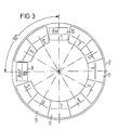
- the upper end cover 2 has two inner lock openings 9 and 10 offset by 90 °, as shown in FIG. 3. In Figure 1, only the lock opening 9 in the end cover 2 can be seen.
- FIG. 3 shows, openings distributed around the circumference of the upper end cover 2 are closed by removable cover segments 11.
- the lower end cap 4 is flanged to the cylindrical inner wall of the electrolyte trough 1, which has a low height compared to the outer wall. Due to the different heights of the outer wall and inner wall of the electrolyte trough 1, a free space is created in the electroplating trough between the upper end cover 2 and the upper end cover 3 on the one hand and the lower end cover 4 on the other hand. This free space is provided for the accommodation of a contacting and holding device, designated overall by 12.
- the contacting and holding device 1.2 consists of a rotor 121, which has a total of 12 equally spaced support arms 122 with sensors 123 at the fork-shaped ends.
- the shaft 124 of the rotor 121 which is centrally aligned with respect to the electrolyte trough 1, is rotatably supported by means of two gas-tight flange bearings 125 and is supported at the bottom on an axial bearing 126 connected to the frame 8.
- the rotor 121 is driven above the upper end cover 3 via bevel gears 127 and 128 by a geared motor 129, which is designed in an explosion-proof design.
- Each of the 12 support arms 122 has a separate cathode connection 130, only the cathode connection for the support arm 122 lying in the sectional plane of FIG. 1 being shown in the drawing.
- the connection of the cathode connections 130 to the associated transducers 123 can take place via carbon brushes and slip rings, but this is not shown in the drawing.
- the free ends of the support arms 122 are fork-shaped and carry at the ends the receptacles 123 which, for the purpose of good contact, have a triangular profile in which the correspondingly designed ends of a transport rod 141 provided with a goods carrier 14 are suspended can.
- the current transfer is favored by the square profile of the contacting pins 142 and the correspondingly designed transducers 123.
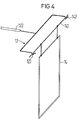
- the goods carrier 14 can, for example, consist of a type of frame to which the workpieces to be aluminized are fastened, for example with the aid of electrically conductive holding wires.
- outer anode segments 16 are arranged in an outer ring and inner anode segments 17 are arranged in an inner ring.
- the outer anode segments 16 are fastened to the outer wall of the electrolyte trough 1 via insulating intermediate pieces, while the inner anode segments are fastened to the inner wall of the electrolyte trough 1 via insulating intermediate pieces.
- the removable lid segments already mentioned 11 of the upper end cover 2 allow a quick exchange of the anode segments 16 and 17 and a change in the anode distance.
- the electroplating trough is charged with a dry protective gas, which is supplied, for example, through a connector 18 attached in the upper cover 3 and metered in such a way that it is always under a slight excess pressure.
- a dry protective gas supplied, for example, through a connector 18 attached in the upper cover 3 and metered in such a way that it is always under a slight excess pressure.
- the electroplating trough forms a space which is closed off to the outside and is exposed to protective gas and which only allows the product carriers to penetrate or be removed through the two inner lock openings 9 and 10 mentioned earlier. So that no ambient air can enter the electroplating trough at these points either, a shaft-shaped condensation chamber 19 is provided above the inner lock opening 9, to which a charging lock 20 is connected.
- the inner lock opening 10 is also provided with a corresponding condensation chamber and a decharging lock, which practically corresponds to the charging lock 20.
- the charging lock 20 consists of a container 201 which is rectangular in plan and in which there is an aprotic solvent 21.
- the container 201 is divided into a prechamber 203 and a main chamber 204 by a partition 202 immersed in the solvent 21, the latter passing into the condensation chamber 19.
- the solvent 21 and the partition 202 immersed in it thus form the liquid lock 205, which makes it impossible for air and moisture to penetrate into the main chamber 204 and thus into the electrolyte 15 even after the prechamber 203 has been flooded with inert gas.
- the antechamber 203 has an inlet opening 206 for the product carriers 14 which can be closed in a vacuum-tight manner and which can then be introduced with the aid of an endless transport chain 22 from the antechamber 203 via the liquid lock 205 into the main chamber 204 and from there via the condensation chamber 19 into the electroplating trough.
- rollers 221 arranged in the side walls of the container 201 provide two transport chains 22 arranged parallel to one another, which can be driven by a geared motor 222 and a countershaft 223 together via a shaft 224.
- Cross carriers 225 are arranged between the transport chains 22, which automatically take the transport rods 141 of the goods carriers 14 with catch hooks 226 and are able to deposit them in the receptacles 123 of the support arms 122.
- the input opening of the prechamber 202 which has preferably been previously flooded with inert gas, is opened, a product carrier 14 with the product to be electroplated is hung on the catch hooks 226 and the input opening 206 is closed again.
- the transport device is then started, the goods carrier 14 being passed through the liquid lock 205 and being released via the main chamber 204 to the receptacles 123 of the support arms 122, the catch hooks 226 automatically detaching from the transport rod 141.
- the removal of the goods carrier 14 takes place in the same way, except that the transport chains move in the opposite direction.
- the catch hooks 226 then automatically grip the transport rod 141 of the goods carrier 14.
- the inner lock openings 9 and 10 can also be closed from the outside with the aid of a cover 23 which can be operated from the outside if necessary. This may be necessary, for example, if the main chamber 204 needs to be ventilated for some reason.
- the condensation chamber 19 in a decharging lock is equipped with spray nozzles 191 for spraying the galvanized goods and the goods carriers with a solvent which is compatible with the electrolyte. If necessary, the lid 23 can also be closed for spraying the goods and the solvent used for spraying can be fed to a separate circuit.
Claims (6)
Priority Applications (1)
| Application Number | Priority Date | Filing Date | Title |
|---|---|---|---|
| AT81108371T ATE12265T1 (de) | 1980-11-28 | 1981-10-15 | Vorrichtung zum galvanischen abscheiden von aluminium. |
Applications Claiming Priority (2)
| Application Number | Priority Date | Filing Date | Title |
|---|---|---|---|
| DE3044975A DE3044975C2 (de) | 1980-11-28 | 1980-11-28 | Vorrichtung zum galvanischen Abscheiden von Aluminium |
| DE3044975 | 1980-11-28 |
Publications (2)
| Publication Number | Publication Date |
|---|---|
| EP0053676A1 EP0053676A1 (fr) | 1982-06-16 |
| EP0053676B1 true EP0053676B1 (fr) | 1985-03-20 |
Family
ID=6117868
Family Applications (1)
| Application Number | Title | Priority Date | Filing Date |
|---|---|---|---|
| EP81108371A Expired EP0053676B1 (fr) | 1980-11-28 | 1981-10-15 | Dispositif pour le dépôt électrolytique de l'aluminium |
Country Status (4)
| Country | Link |
|---|---|
| US (1) | US4363712A (fr) |
| EP (1) | EP0053676B1 (fr) |
| AT (1) | ATE12265T1 (fr) |
| DE (2) | DE3044975C2 (fr) |
Families Citing this family (9)
| Publication number | Priority date | Publication date | Assignee | Title |
|---|---|---|---|---|
| DE3102021C2 (de) * | 1981-01-22 | 1984-02-23 | Siemens AG, 1000 Berlin und 8000 München | Vorrichtung zum galvanischen Abscheiden von Aluminium |
| DE3133232A1 (de) * | 1981-08-21 | 1983-03-10 | Siemens AG, 1000 Berlin und 8000 München | Vorrichtung zum galvanischen abscheiden von aluminium |
| DE3133162C2 (de) * | 1981-08-21 | 1984-08-02 | Siemens AG, 1000 Berlin und 8000 München | Vorrichtung zum galvanischen Abscheiden von Aluminium |
| DE3231855A1 (de) * | 1982-08-26 | 1984-03-01 | Siemens AG, 1000 Berlin und 8000 München | Vorrichtung zum galvanischen abscheiden von aluminium |
| DE3609077A1 (de) * | 1986-03-18 | 1987-09-24 | Karl Trometer | Verfahren und vorrichtung zum aufbringen galvanischer ueberzuege |
| US4759831A (en) * | 1986-07-04 | 1988-07-26 | Siemens Aktiengesellschaft | Electroplating apparatus particularly for electro-deposition of aluminum |
| JP3016060B2 (ja) * | 1993-04-28 | 2000-03-06 | 本田技研工業株式会社 | 防振マウント装置 |
| EP1510600A1 (fr) * | 2003-08-26 | 2005-03-02 | Aluminal Oberflächtentechnik GmbH & Co. KG | Procédé et dispositif pour le revêtement de métal et alliages de métaux à partir d'électrolytes organométalliques |
| DE102004032659B4 (de) | 2004-07-01 | 2008-10-30 | Atotech Deutschland Gmbh | Vorrichtung und Verfahren zum chemischen oder elektrolytischen Behandeln von Behandlungsgut sowie die Verwendung der Vorrichtung |
Family Cites Families (3)
| Publication number | Priority date | Publication date | Assignee | Title |
|---|---|---|---|---|
| DE2716805C3 (de) * | 1977-04-15 | 1979-10-31 | Siemens Ag, 1000 Berlin Und 8000 Muenchen | Vorrichtung zum galvanischen Abscheiden von Aluminium |
| DE2719680A1 (de) * | 1977-05-03 | 1978-11-09 | Montblanc Simplo Gmbh | Anlage zum aluminieren |
| DE2901586A1 (de) * | 1979-01-17 | 1980-07-31 | Montblanc Simplo Gmbh | Aluminierzelle |
-
1980
- 1980-11-28 DE DE3044975A patent/DE3044975C2/de not_active Expired
-
1981
- 1981-10-15 DE DE8181108371T patent/DE3169426D1/de not_active Expired
- 1981-10-15 EP EP81108371A patent/EP0053676B1/fr not_active Expired
- 1981-10-15 AT AT81108371T patent/ATE12265T1/de not_active IP Right Cessation
- 1981-11-06 US US06/318,812 patent/US4363712A/en not_active Expired - Fee Related
Also Published As
| Publication number | Publication date |
|---|---|
| EP0053676A1 (fr) | 1982-06-16 |
| DE3044975C2 (de) | 1985-10-31 |
| ATE12265T1 (de) | 1985-04-15 |
| DE3044975A1 (de) | 1982-06-03 |
| US4363712A (en) | 1982-12-14 |
| DE3169426D1 (en) | 1985-04-25 |
Similar Documents
| Publication | Publication Date | Title |
|---|---|---|
| EP0376222B1 (fr) | Procédé et appareillage pour le dépôt par électrophorèse d'une laque sur de petits objets en vrac | |
| EP0053676B1 (fr) | Dispositif pour le dépôt électrolytique de l'aluminium | |
| EP0070011B1 (fr) | Dispositif de galvanisation | |
| EP0042503B1 (fr) | Appareillage pour le dépôt d'aluminium par voie électrolytique | |
| DE2716805C3 (de) | Vorrichtung zum galvanischen Abscheiden von Aluminium | |
| DE19713203C1 (de) | Vorrichtung und Verfahren zum Oberflächenbehandeln durch Tauchen | |
| EP0209016B1 (fr) | Dispositif de traitement électrolytique d'objets en vrac | |
| EP0072969B1 (fr) | Installation pour le dépôt électrolytique de l'aluminium | |
| DD202460A5 (de) | Vorrichtung zum galvanischen abscheiden von aluminium | |
| EP0286880B1 (fr) | Dispositif de séchage pour marchandises en vrac | |
| EP0056844B1 (fr) | Dispositif pour le dépôt électrolytique de l'aluminium | |
| EP0209766B1 (fr) | Dispositif de traitement électrolytique d'objets en vrac | |
| EP0251272B1 (fr) | Dispositif pour l'électrodéposition, en particulier de l'aluminium | |
| EP0220419B1 (fr) | Installation de traitement électrolytique de pièces en vrac | |
| DE3023405C2 (de) | Vorrichtung und Verfahren zum galvanischen Abscheiden von Aluminium | |
| EP0209015B1 (fr) | Dispositif de traitement électrolytique d'objets en vrac | |
| DE3319544C2 (fr) | ||
| DE3048511A1 (de) | Vorrichtung zum galvanischen abscheiden von aluminium | |
| DE3519906C1 (de) | Verfahren und Vorrichtung zur galvanischen Beschichtung eines Hohlkörpers mit verschieden gerichteten Ausnehmungen oder Hinterschneidungen und die Anwendung des Verfahrens | |
| EP0211239B1 (fr) | Dispositif pour le traitement d'objets en vrac | |
| EP1658393B1 (fr) | Dispositif et procede pour deposer des metaux et/ou alliages metalliques a partir d'electrolytes metallo-organiques |
Legal Events
| Date | Code | Title | Description |
|---|---|---|---|
| PUAI | Public reference made under article 153(3) epc to a published international application that has entered the european phase |
Free format text: ORIGINAL CODE: 0009012 |
|
| 17P | Request for examination filed |
Effective date: 19811015 |
|
| AK | Designated contracting states |
Designated state(s): AT BE CH DE FR GB IT NL SE |
|
| ITF | It: translation for a ep patent filed |
Owner name: STUDIO JAUMANN |
|
| GRAA | (expected) grant |
Free format text: ORIGINAL CODE: 0009210 |
|
| AK | Designated contracting states |
Designated state(s): AT BE CH DE FR GB IT LI NL SE |
|
| REF | Corresponds to: |
Ref document number: 12265 Country of ref document: AT Date of ref document: 19850415 Kind code of ref document: T |
|
| REF | Corresponds to: |
Ref document number: 3169426 Country of ref document: DE Date of ref document: 19850425 |
|
| ET | Fr: translation filed | ||
| PLBE | No opposition filed within time limit |
Free format text: ORIGINAL CODE: 0009261 |
|
| STAA | Information on the status of an ep patent application or granted ep patent |
Free format text: STATUS: NO OPPOSITION FILED WITHIN TIME LIMIT |
|
| 26N | No opposition filed | ||
| PGFP | Annual fee paid to national office [announced via postgrant information from national office to epo] |
Ref country code: GB Payment date: 19910913 Year of fee payment: 11 |
|
| PGFP | Annual fee paid to national office [announced via postgrant information from national office to epo] |
Ref country code: AT Payment date: 19910918 Year of fee payment: 11 |
|
| PGFP | Annual fee paid to national office [announced via postgrant information from national office to epo] |
Ref country code: SE Payment date: 19911017 Year of fee payment: 11 |
|
| PGFP | Annual fee paid to national office [announced via postgrant information from national office to epo] |
Ref country code: FR Payment date: 19911022 Year of fee payment: 11 |
|
| PGFP | Annual fee paid to national office [announced via postgrant information from national office to epo] |
Ref country code: BE Payment date: 19911023 Year of fee payment: 11 |
|
| ITTA | It: last paid annual fee | ||
| PGFP | Annual fee paid to national office [announced via postgrant information from national office to epo] |
Ref country code: NL Payment date: 19911031 Year of fee payment: 11 |
|
| PGFP | Annual fee paid to national office [announced via postgrant information from national office to epo] |
Ref country code: DE Payment date: 19911217 Year of fee payment: 11 |
|
| PGFP | Annual fee paid to national office [announced via postgrant information from national office to epo] |
Ref country code: CH Payment date: 19920124 Year of fee payment: 11 |
|
| PG25 | Lapsed in a contracting state [announced via postgrant information from national office to epo] |
Ref country code: GB Effective date: 19921015 Ref country code: AT Effective date: 19921015 |
|
| PG25 | Lapsed in a contracting state [announced via postgrant information from national office to epo] |
Ref country code: SE Effective date: 19921016 |
|
| PG25 | Lapsed in a contracting state [announced via postgrant information from national office to epo] |
Ref country code: LI Effective date: 19921031 Ref country code: CH Effective date: 19921031 Ref country code: BE Effective date: 19921031 |
|
| BERE | Be: lapsed |
Owner name: SIEMENS A.G. BERLIN UND MUNCHEN Effective date: 19921031 |
|
| PG25 | Lapsed in a contracting state [announced via postgrant information from national office to epo] |
Ref country code: NL Effective date: 19930501 |
|
| GBPC | Gb: european patent ceased through non-payment of renewal fee |
Effective date: 19921015 |
|
| NLV4 | Nl: lapsed or anulled due to non-payment of the annual fee | ||
| PG25 | Lapsed in a contracting state [announced via postgrant information from national office to epo] |
Ref country code: FR Effective date: 19930630 |
|
| REG | Reference to a national code |
Ref country code: CH Ref legal event code: PL |
|
| PG25 | Lapsed in a contracting state [announced via postgrant information from national office to epo] |
Ref country code: DE Effective date: 19930701 |
|
| REG | Reference to a national code |
Ref country code: FR Ref legal event code: ST |
|
| EUG | Se: european patent has lapsed |
Ref document number: 81108371.6 Effective date: 19930510 |