EP0053281A2 - Gasentladungs-Leuchtkörper mit Kaltelektroden - Google Patents
Gasentladungs-Leuchtkörper mit Kaltelektroden Download PDFInfo
- Publication number
- EP0053281A2 EP0053281A2 EP81109023A EP81109023A EP0053281A2 EP 0053281 A2 EP0053281 A2 EP 0053281A2 EP 81109023 A EP81109023 A EP 81109023A EP 81109023 A EP81109023 A EP 81109023A EP 0053281 A2 EP0053281 A2 EP 0053281A2
- Authority
- EP
- European Patent Office
- Prior art keywords
- vessel
- luminous element
- element according
- luminous
- wall
- Prior art date
- Legal status (The legal status is an assumption and is not a legal conclusion. Google has not performed a legal analysis and makes no representation as to the accuracy of the status listed.)
- Granted
Links
Images

Classifications
-
- H—ELECTRICITY
- H01—ELECTRIC ELEMENTS
- H01J—ELECTRIC DISCHARGE TUBES OR DISCHARGE LAMPS
- H01J61/00—Gas-discharge or vapour-discharge lamps
- H01J61/02—Details
- H01J61/30—Vessels; Containers
- H01J61/32—Special longitudinal shape, e.g. for advertising purposes
Definitions
- the invention relates to a luminous element, the gas discharge lamp of which is equipped with cold electrodes and the efficiency of which significantly exceeds that of the known means previously used as luminous elements.
- Luminous elements are components that are used both in lighting technology and in display technology / z.
- B. To a large extent determine the number and quality of the services that can be achieved with the given luminous element, the reliability of the services and the effects of the use of these components on the investment and operating costs of the systems and system networks equipped with such systems and also the applicability of the entire system.
- incandescent lamps which are mainly used due to various advantageous peculiarities in lighting technology, is their low efficiency when converting electrical energy into light energy. It follows from the known mechanism of action of the incandescent lamp that the z. Currently achievable efficiency of 3-5% compared to a significant improvement is not to be expected; the efficiency of the incandescent lamp is expected to remain in this range in the future. The existing heat effect of the incandescent lamp, which is responsible for the poor efficiency, also leads to further technical disadvantages.
- the efficiency that can be achieved in principle in the case of gas discharge lamps with cold electrodes cannot even be achieved with known components of this type.
- the energy requirement of the discharge lamps filled with noble gas varies greatly depending on the type, not only depends on the electrode spacing, but also on the filling pressure.
- the efficiency would be optimal if the discharge lamp were operated with the optimum filling pressure determined on the basis of the known relationships, that is to say the filling pressure value which is already sufficient to ensure ignition in the discharge space. In practice, however, a larger filling pressure must be used.
- the electrodes arranged in the discharge space and the metal particles emerging from them during operation absorb gas, and the original optimally set filling pressure is then reduced; the resulting pressure is no longer sufficient for reliable continuous operation.
- the efficiency ie the light useful power obtained with an electrical power unit fed in, is further reduced if, as is often the case, light directing means and means / cover plate, hood, etc. / which protect against mechanical damage are used, which also absorb light energy. Even if the transparent protective hood encompassing the luminous element is well visible from one light material is made, a considerable part of the light energy is still absorbed.
- the invention is based on the finding that the operating outlay in the case of gas discharge lamps with cold electrodes can be optimally reduced if direct contact between the discharge medium and the electrodes which excite the electrical field for the discharge is ruled out in such a way that the electrodes are separated from the Discharge medium are isolated by a glass layer which is electrically conductive and is therefore suitable for feeding the electrical energy conducted from the feed network to the electrodes - under the operating conditions of the given discharge lamp - into the discharge space.
- glass can be converted into an electrically conductive or semi-conductive / iw: conductive / medium by means of certain additions. In other areas of application, such conductive glass has already been used for other purposes. If the discharge lamp designed with cold electrodes is arranged in a vessel, the wall thereof is at least partially consists of - for electrodes or ion current - conductive glass, then the direct contact between the electrode and the discharge medium can be excluded and the electrical field necessary for the discharge can still be excited with optimal efficiency.
- the entire surface of the vessel wall of a luminous element fed with high frequency can consist of conductive glass, e.g. B. made of glass containing sodium / oxide / or lithium / oxide /. If the energy transfer takes place by means of electron current, the section of the vessel lying between two adjacent electrodes to be switched at different potentials is made of electrically non-conductive glass, and those sections which are each in contact with only one electrode are made of conductive glass. If necessary, the vessel of the filament can also consist entirely of conductive glass for energy transmission by means of electron current if the field is excited with high frequency and only a so-called outer electrode is in contact with the vessel, while the other potential is represented by ambient air space.
- conductive glass e.g. B. made of glass containing sodium / oxide / or lithium / oxide /.
- high frequency is used in this description for frequencies that are higher than the mains frequency.
- the effect according to the invention can also be achieved if the vessel wall - or a part thereof - is not made of conductive glass, but the electrode in the interior of the vessel is covered with conductive glass.
- This electrode is either arranged in the interior of the vessel or it projects into the interior of the vessel through the vessel wall made of non-conductive glass. inside.
- the vessel - or at least a part of it - is made of conductive glass
- the electrode (s) within the vessel is / are covered with conductive glass.
- the luminous element according to the invention can be filled to an optimal filling pressure; there can be no interaction between the electrode and the discharge medium, which would influence the pressure conditions in the discharge space, the efficiency of the operation increases significantly, namely in a design which does not impose any further restrictions on the known solutions, which increases the variability in order to achieve various additional ones Services related; the characteristics according to the invention can therefore be combined with numerous other characteristics, whereby this combination can partly make it possible to enjoy the mode of operation according to the invention supplemented with other effects known in the art, and partly it is also possible to achieve such resulting effects which are not at all possible with known gas discharge lamps were possible.
- the luminous element can also be provided with a cover element which is arranged in the vicinity of the vessel delimiting the discharge space, along the vessel jacket or a part thereof.
- This cover body is used for mechanical protection and / or as a light guide, can be designed as a closed protective hood and can also form light guide walls or light guide shafts.
- the vessel of the luminous body provided with an external cover body is made of a material which not only allows visible light to pass through, but e.g. B. also the ultraviolet radiation, then the luminous area can be increased further by covering the protective cover or the cover body on the inner wall with a luminescent layer or by making the wall itself from a substance containing luminescent particles.
- the characteristic of the cold electrode gas discharge luminous bodies which is known per se, can also be exploited, that the shape formation can be varied in many ways.
- the display can be adapted to the desired image and / or its desired color tone even better if the vessel is corresponding the shape of the envelope of the image to be displayed and more than one gas discharge cell is formed in the vessel, which cells are insulated from one another - as far as the electrical contact is concerned.
- either two electrodes can be arranged in the cell for each individual cell or it is in the common discharge space - z. B. in its focus - a central electrode and one cell electrode in each cell.
- one electrode is expediently arranged in each cell, which electrodes form the counter electrode in cascade fashion for the respectively adjacent electrodes, so that a discharge arc is formed between the respectively adjacent two electrodes.
- the luminous element according to the invention can be operated by using phosphor with the desired color tint. If the luminous element consists of several discharge cells, the inner walls of all cells can be covered with the same-colored phosphor as a variant; In this case, the division into separate discharge cells only serves to better illustrate the desired profile or the possibility of lighting different sections of the image at different times. However, it is also possible to apply fluorescent phosphor of different colors, or to use phosphor of the same color in at least some of the cells.
- a glass-technical, vacuum-technical specialist can use the specialist literature on the conductive glass to determine the additions by means of which the substance at least a part of the vessel wall / or the electrode coating / can be provided with such conductivity properties that are optimally favorable at the specific place of use, and even the lighting technician can use the specialist literature on cold electrode gas discharge tubes to construct very varied embodiments, depending on the image shape and operational variability desired at the place of use. I. w. the applicability of the invention is nevertheless illustrated by means of a few examples.
- the framework of the oxide-containing glass forms the so-called structure-forming media, while the structure-modifying media are contained in the cavities of the framework.
- Structural are z.
- Oxides of an alkali metal or alkaline earth metal can have a modifying effect.
- Oxides of magnesium, lead or aluminum can have both a forming and a modifying effect.
- alkali metal oxide For some types of glass the content of alkali metal oxide (s) must be increased in order to achieve the maximum conductivity. Oxides of divalent metals, e.g. B. ZnO or Mg0 and the use of CaO or Pb0 must be avoided. The influence of an oxide on the conductivity of the glass depends on its quantity and the original composition of the glass. For this purpose, various elements of groups III, IV, V or VI of the periodic system can be used.
- the glass can become clearly electron current conductive if elements of the oxygen group are added, whereby two, three and also more components can be added.
- elements of the oxygen group are added, whereby two, three and also more components can be added.
- the geometry of the discharge chamber (s) is illustrated by means of a few exemplary embodiments and an example of the glass coating of the electrode is also given.
- the envelope that hermetically seals the evacuated space is often called a bulb in lighting technology if it is a gas discharge device and the envelope can be viewed as a discharge vessel. Since the luminous element according to the invention can now be used in versions in which it is difficult to call the envelope hermetically enclosing the discharge space as a bulb, the more general description of the vessel is also given in the examples and in the claims, which of course also commonly referred to as the bulb Embodiments includes.
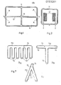
- Figure 1 is a schematic top view of a light source with four discharge cells in a common gas space.
- Figure 2 shows the section of the schematic side view of a mains-operated block-shaped light source.
- Figure 3 illustrates the coating of the electrode with conductive glass
- Figure 4 shows the design of the filament with the outer electrode.
- Figure 5 shows a filament, the vessel of which is formed by a non-conductive section and two half-pistons made of conductive glass fused to it on both sides.
- Figure 6 illustrates an embodiment in which the vessel wall is also made of conductive glass and a transparent, conductive coating is also attached to the outer or inner wall of the vessel.
- Figure 7 shows some examples of the shape-related arrangement of the electrodes in the discharge space.
- partitions 12 divide the vessel 11 into four discharge cells in such a way that, as a result of the communication between the cells, the discharge medium fills the entire interior of the luminous element in a coherent manner.
- a central electrode 13 is arranged - in the gap existing between the ends of the intermediate walls 12 - and a cell electrode 14 in each cell.
- a fitting 15 made of fluorescent material is attached to the inner wall of the vessel 11 which fluorescent is of different color by cell.
- the lead wires of the cell electrodes 14 are connected to the corresponding terminals of an electronic sequencer, which is not shown; there is thus the possibility of activating the individual discharge cells sequentially according to a desired light display game, it being possible, of course, to control both only one cell and several cells at the same time.
- the contour line of the vessel 21 in FIG. 2 is similar to the contour line of the vessel 11 in FIG. 1, but a single discharge space is formed within the vessel wall with two relatively large electrodes 22.
- the area ratios of the discharge space shown in the illustration and the electrodes 22 show dimensionally, under which conditions the luminous element according to the invention works as a mains-fed luminous source with the mode of operation according to the invention.
- FIG 3.a the vessel 31 of the filament (part of the same) and the electrode 32 hermetically carried through the wall thereof are shown, the part of which protrudes into the vessel 31 is insulated from the discharge medium by a coating 34 made of conductive glass.
- the coating 34 is fused to the wall of the vessel 31 at the cross sections 33.
- Figure 3.b shows the already coated electrode 32 in the state prepared for melting.
- Gas discharge lamps with an external electrode are well known in the art.
- the corresponding - but designed according to the invention - lamp differs from the known designs in that the part of the vessel 41 / Fig. 4 /, with which the outer electrode 42 / in the example shown has a wire electrode / contact, is made of conductive glass.
- Figure 4.a shows the bulb part 411 made of non-conductive glass and the bulb part 412 made of conductive glass in the state prepared for the fusion
- Figure 4.b shows the already assembled vessel 41 with the weld seam in cross-section 43. Also the one made of the corresponding phosphor Fitting 44 is shown.
- FIG. 5 shows the embodiment in which the energy exciting the discharge field is fed in via two outer electrodes 521 and 522.
- the two vessel parts 511 and 512 are made of conductive glass and have contact with only one outer electrode 521 or 522, and these vessel parts 511 and 512 are made of a non-conductive glass standing section 53 fused over its cross-sections 54 on both sides and thus form the hermetically sealed vessel 51.
- Figure 5.a shows the parts of the vessel 51 mentioned before the fusion with the fitting 55 made of fluorescent material and attached to the inner walls;
- Figure 5.b shows the mounted lamp.
- Figure 6 shows schematically a luminous element in two different versions, in which the field energy is fed in via two outer electrodes 621 and 622.
- the vessel 61 made of conductive glass which carry the outer electrodes 621 and 622; these are fused along the cross sections 64 to the two ends of a cylinder tube 613 made of non-conductive glass.
- the major part of the cylindrical section of the filament consists of conventional glass, i.e. a much longer section as in the version according to Figure 5 / Section 53 /.
- the effectiveness of the coupling is not guaranteed here by the fact that conductive glass delimits the discharge space almost the entire length of the filament, but by the fact that the inner or outer wall / Fig.
- 6.b or 6.a / of the cylinder tube 613 consisting of conventional glass is provided with an electrically conductive coating 63 such that it always has electrical contact with only one of the outer electrodes 621 and 622 from the other outer electrode; 622 or 621 is insulated to avoid a short circuit.
- an electrically conductive coating 63 such that it always has electrical contact with only one of the outer electrodes 621 and 622 from the other outer electrode; 622 or 621 is insulated to avoid a short circuit.
- the coating 63 is interrupted in the middle of the cylinder tube 613, so that practically the same coupling conditions exist for both outer electrodes 621 and 622.
- Figure 7 illustrates how the division of the common discharge space over several discharge cells facilitates and improves the display of the respective - regular or irregular - profile.
- Figure 7.a shows a comb profile, 7.b a T profile, 7.c an A profile.
- the vessels 711, 712, 713 enclose an ionization space 73 in which an electrode 72 is arranged near the end points of the homogeneous profile parts, so that the discharge arc encompasses the entire contour line of the profile.
- FIGS 1 to 7 are of course only an example of an illustration; It is obvious that the illuminants according to the invention can be realized in many variants and embodiments, which means that the installation of the conductive glass in the vessels of the illuminants, or the conviction of the electrodes with conductive glass, the choice of the geometry and the material properties, etc . concerns without thereby deviating from the inventive idea.
- the luminous elements according to the invention can be designed, inter alia, for the following applications: for luminous dots in a luminous display field, for signal lamps, as a special lamp for dark rooms, as components in matrix-shaped display panels for the reproduction of television or film images. With luminous bodies according to the invention, large-scale light panels, slide projectors, X-ray fluoroscopy devices, signal lights, numerical display devices can be fitted, which are from the network, from a battery or from the company's own AC sources can be operated.
- a suitable method for increasing the luminous area is best pouring the luminous element into a transparent or transparent support frame; so can with a bunch of elementary.
- Luminous bodies with a base area of a few millimeters or centimeters each have a homogeneous luminous panel of any size and any color tone / color distribution / which ensures uniform luminous intensity in all places and in all directions.
- Luminous bodies that are intended to display an inscription, a picture, a text, an alphanumeric character or a walking font can also be encased in this way. This not only extends the field of application of the luminous bodies according to the invention, but also significantly increases the aesthetic effect.
- the frame does not necessarily have to be extensively manufactured in the pouring process.
- the frame can also be poured out as an intermediate product or can be produced on the rolling path or in such a way that cavities are left free for the lighting elements in a corresponding distribution and number, with / each / a subsequently hermetically sealable evacuation channel. These cavities are first provided with a wall covering made of the appropriate phosphor, then the evacuation is carried out and the appropriate discharge medium is filled in; when the optimal filling pressure is reached, the evacuation channel is closed on the melting path.
- the cast materials and glass plates can also be colored accordingly if necessary; Dye or fluorescent material can be added to the material can be mixed or an appropriate coating can be applied.
- the coating can of course consist of permanent fluorescent; Thus, even with periodic excitation, the impression of continual lighting can arise if the mode of operation is adapted to the sluggishness of the face; the feed energy can be used even cheaper.
Landscapes
- Vessels And Coating Films For Discharge Lamps (AREA)
- Gas-Filled Discharge Tubes (AREA)
- Discharge Lamps And Accessories Thereof (AREA)
- Endoscopes (AREA)
- Luminescent Compositions (AREA)
- Stringed Musical Instruments (AREA)
- Investigating, Analyzing Materials By Fluorescence Or Luminescence (AREA)
- Breeding Of Plants And Reproduction By Means Of Culturing (AREA)
- Farming Of Fish And Shellfish (AREA)
Abstract
Description
- Gegenstand der Erfindung ist ein Leuchtkörper, dessen Gasentladungslampe mit Kaltelektroden bestückt ist und dessen Wirkungsgrad denjenigen der bislang als Leuchtkörper angewandten bekannten Mittel bedeutend übertrifft.
- Leuchtkörper sind Bauteile, die sowohl in der Beleuchtungstechnik, als auch in der Anzeigetechnik /z. B. Reklame oder Lichtanzeige i. a., insbesondere Datenanzeige in der Gerätetechnik/ weitverbreitet angewendet werden und deren anwendungstechnische Eigenschaften /z. B. Anzahl und Qualität der mit dem gegebenen Leuchtkörper erzielbaren Dienstleistungen, Zuverlässigkeit der Dienstleistungen und die Auswirkungen der Anwendung dieser Bauteile auf die Investitions- und Betriebskosten der mit solchen bestückten Anlagen und Anlagennetzen/ auch die Anwendbarkeit der ganzen Anlage weitgehend bestimmen.
- Einer der bedeutendsten Nachteile der wegen verschiedener vorteilhafter Eigenheiten in der Beleuchtungstechnik vorwiegend angewendeten Glühlampen ist deren geringer Wirkungsgrad beim Konvertieren von elektrischer in Lichtenergie. Es folgt aus dem bekannten Wirkmechanismus der Glühlampe, dass dem z. Z. erreichbaren Wirkungsgrad von üblich 3-5 % gegenüber eine wesentliche Verbesserung nicht zu erwarten ist; der Wirkungsgrad der Glühlampe wird voraussichtlich auch in der Zukunft in dieser Grössenordnung bleiben. Die bei der Glühlampe bestehende Wärmewirkung, die ja den schlechten Wirkungsgrad verurscht, führt auch zu weiteren anwendungstechnischen Nachteilen.
- Gasentladungs-Leuchtkörper mit Kaltelektroden ermöglichen einen weit besseren Wirkungsgrad und auch die anderen Folgen der Wärmebildung können vermieden werden; auch die zeitgebundenen leuchttechni-Effekte können besser gehandhabt werden, als bei der Glühlampe. Es ist z. B. bekannt, dass bei der weitverbreiteten Anwendung der Glühlampe in der Anzeigetechnik eine Mannigfaltigkeit der Dienstleistungsvarianten durch die Tatsache begrenzt wird, dass wegen des langwierigen Nachleuchtens der Glühlampe nur ein Teil der erwünschten Effekte erzielbar ist, die auf der Trägheit des Auges beruhen und auch dieser Teil nur mit einem hohen Aufwand an Bauteilen und Steuertechnik.
- Der im Prinzip bei Gasentladungs-Leuchtkörpern mit Kaltelektroden erreichbare Wirkungsgrad kann aber mit bekannten solchen Bauteilen nicht einmal annährend erzielt werden. Der Energiebedarf der mit Edelgas gefüllten Entladungslampen ist typenbedingt sehr verschieden, hängt nicht nur vom Elektrodenabstand ab, sondern auch vom Fülldruck. Der Wirkungsgrad wäre optimal, wenn man die Entladungslampe mit dem auf Grund der bekannten Zusammenhänge bestimmten optimalen Fülldruck betreiben würde, also dem Fülldruckwert, der schon ausreichend ist, um das Zünden im Entladungsraum zu gewährleisten. In der Praxis muss man aber einen grösseren Fülldruck anwenden. Die im Entladungsraum angeordneten Elektroden und die von diesen während des Betriebes austretenden Metallpartikel absorbieren Gas und dadurch vermindert sich dann der ursprünglich optimal eingestellte Fülldruck; der infolgedessen bestehende Druck ist für den zuverlässigen Dauerbetrieb schon nicht mehr ausreichend. Darum wird üblich viel mehr Edelgas in den Entladungsraum gefüllt, als theoretisch notwendig wäre. Die Lebensdauer wird zwar derweise - in kleinem Masse - erhöht, aber im Betrieb erhöht sich sowohl der Energieverbrauch, als auch die Belastung der Elektroden. Die in der Lampe entstehende Verunreinigung vermindert auch die Aktivität der leuchtenden Substanz bedeutend.
- Der Wirkungsgrad, d. h. die mit einer eingespeisten elektrischen Leistungseinheit gewonnene Lichtnutzleistung wird noch vermindert, wenn - wie oft üblich - Lichtlenkmittel und gegen mechanische Beschädigung schützende Mittel /Abdeckplatte, Haube usw./ angewendet werden, die ja auch Lichtenergie absorbieren. Auch wenn die den Leuchtkörper umfassende transparente Schutzhaube aus einem Licht gut durchlassenden Material angefertigt ist, wird noch immer ein ansehnlicher Teil der Leuchtenergie absorbiert.
- Die Möglichkeit, den Wirkungsgrad verbessernde Massnahmen zu treffen, ist aber sehr beschränkt, weil man am jeweiligen Anwendugsort verschiedenen Anforderungen genügen muss. Bei solchem Bestreben wird man mit sehr komplizierten Problemen konfrontiert und nur deren allseitige Ausräumung verspricht Erfolg. Die Entwicklungstätigkeit auf dem Gebiet der Leuchtkörper stellt sich auch heutzutage als Haupzziel, dass die im Betrieb verbrauchte elektrische Energie - am gegebenen Ort und eventuell in entsprechender zeitlicher Verteilung - mit möglichst wenig Verlust in Lichtenergie konvertiert werden könne.
- Die Erfindung fusst auf der Erkenntnis, dass der Betriebsaufwand bei den Gasentladungs-Leuchtkörpern mit Kaltelektroden optimal vermindert werden kann, wenn ein unmittelbarer Kontakt zwischen dem Entladungsmedium und den Elektroden, die das elektrische Feld für die Entladung erregen, derart ausgeschlossen wird, dass die Elektroden vom Entladungsmedium durch eine Glasschicht isoliert werden, welche elektrisch leitfähig und daher geeignet ist, die vom Speisenetz zu den Elektroden geleitete elektrische Energie - unter den Betriebsbedingungen der gegebenen Entladungslampe - in den Entladungsraum einzuspeisen.
- Es ist bekannt, dass man mittels bestimmter Zugaben Glas in ein elektrisch leitendes oder halbleitendes /i.w.:leitendes/ Medium umwandeln kann. In anderen Anwendungsgebieten wurde solches leitfähiges Glas für andere Zwecke schon benützt. Wenn die mit Kaltelektroden ausgeführte Entladungslampe in einem Gefäss angeordnet wird, dessen Wand mindestens zum Teil aus - für Elektroden oder Ionenstrom - leitfähigem Glas besteht, dann kann der unmittelbare Kontakt zwischen Elektrode und Entladungsmedium ausgeschlossen und das für die Entladung notwendige elektrische Feld im Entladungsraum dennoch mit optimalem Wirkungsgrad erregt werden.
- Wenn die Energieeinspeisung mittels Ionenstrom erfolgt, kann sogar die Gesamtfläche der Gefässwand eines mit Hochfrequenz gespeisten Leuchtkörpers aus leitfähigem Glas bestehen, z. B. aus Glas, welches Natrium/oxyd/ oder Lithium/oxyd/ enthält. Erfolgt die Energieübertragung mittels Elektronenstrom, dann wird der jeweils zwischen zwei benachbarten, an verschiedene Potentiale zu schaltenden Elektroden liegende Abschnitt des Gefässes aus elektrisch nicht leitendem Glas angefertigt, und diejenigen Anschnitte, die jeweils mit nur einer Elektrode in Berührung sind, aus leitfähigem Glas. Gegebenenfalls kann auch für Energieübertragung mittels Elektronenstrom das Gefäss des Leuchtkörpers völlig aus leitfähigem Glas bestehen, wenn das Feld mit Hochfrequenz erregt wird und nur eine sogenannte Aussenelektrode mit dem Gefäss Kontakt hat, während das andere Potential durch Umgebungsluftraum repräsentiert wird.
- Die Bezeichnung Hochfrequenz wird in dieser Beschreibung für Frequenzen angewendet, die höher sind als die Netzfrequenz.
- Die erfindungsgemässe Wirkung kann auch erzielt werden, wenn nicht die Gefässwand - oder ein Teil derselben - aus leitfähigem Glas besteht, sondern die Elektrode im Gefässinneren mit leitfähigem Glas überzogen ist. Diese Elektrode ist entweder im Gefässinneren angeordnet oder sie ragt - durch die aus nicht leitendem Glas bestehende Gefässwand durchgeführt - ins Gefässinnere. hinein.
- Die beiden Varianten können auch kombiniert werden: einerseits ist das Gefäss - oder mindenstens ein Teil desselben - aus leitfähigem Glass, anderseits ist /sind/ auch die Elektrode/n/ innerhalb des Gefässes mit leitfähigem Glas überzogen.
- Der erfindungsgemässe Leuchtkörper kann auf optimalen Fülldruck gefüllt werden; zwischen der Elektrode und dem Entladungsmedium kann keine Wechselwirkung auftreten, welche die Druckverhältnisse im Entladungsraum beeinflussen würde, der Wirkungsgrad des Betriebes erhöht sich bedeutend und zwar in einer konstruktiven Ausführung, welche den bekannten Lösungen gegenüber keine weiteren Beschränkungen auferlegt, was die Variabilität zwecks Erzielung verschiedener zusätzlicher Dienstleistungen betrifft; die erfindungsgemässen Kennzeichen können daher mit zahlreichen weiteren Kennzeichen kombiniert werden, wobei diese Kombination teils ermöglichen kann, die erfindungsgemässe Wirkungsweise mit weiteren an sicht bekannten Effekten ergänzt zu geniessen, und teils auch solche resultierende Effekte erzielt werden können, die bei bekannten Gasentladungs-Leuchtkörpern überhaupt nicht möglich waren.
- Aus dem bisherigen folgt auch, dass die vollkommene Isolierung der Elektrode vom Entladungsmedium nicht nur den Wirkungsgrad, sondern auch die Lebensdauer des Entladungssystems entsprechend erhöht. Ferner kommt auch die Verminderung der Zündspannung und des Betriebsstromes nicht nur dem Wirkungsgrad und der Lebensdauer zugute, sondern bietet auch günstigere Bedingungen für die Konstruktion,/Dimensionen, Wahl der Substanz, Geometrie, usw./.
- Es besteht auch die Möglichkeit, auf die Innenwand des teilweise aus leitfähigem Glass bestehenden Gefässes - praktisch auf die Gesamtfläche der Innenwand - einen leitfähigen Überzug /Metalloxyd/ aufzubringen derweise, dass das leitfähige Metalloxyd in einen an sich bekannten Trägerstoff gebettet wird, welcher die Metalloxyd-Teilchen nicht in das Vakuum diffundieren lässt, aber dabei die stromleitende Funktion des Metalloxyds nicht hindert.
- Der Leuchtkörper kann auch mit einem Abdeckkörper versehen sein, der in der Umgebung des den Entladungsraum begrenzenden Gefässes, längs des Gefässmantels oder eines Teils desselben angeordnet ist. Dieser Abdeckkörper dient dem mechanischen Schutz und/oder als Lichtlenkmittel, kann sowohl als geschlossene Schutzhaube ausgeführt werden als auch Lichtlenkwände bzw. Lichtlenkschächte bilden.
- Wird das Gefäss des mit einem externen Abdeckörper versehenen Leuchtkörpers aus einem Stoff gefertigt, welcher nicht nur das sichtbare Licht durchlässt, sondern z. B. auch die ultraviolette Strahlung, dann kann die Leuchtfläche weiter erhöht werden, indem man die Schutzhaube, bzw. den Abdeckkörper an der Innenwand mit einer lumineszenten Schicht überzieht oder die Wand selbst aus einem lumineszente Partikel enthaltenden Stoff anfertigt.
- Auch bei den erfindungsgemässen Leuchtkörpern kann die an sich bekannte Eigenheit der Kalteelektroden-Gasentladungsleuchtkörper ausgenützt werden, dass die Formbildung mannigfaltig variiert werden kann. Man kann z. B. die Gestellt der Entladungskammer /Röhre/ so wählen, dass sie dem anzuzeigenden Bild, bzw. alphanumerischen Charakter entspreche; in diesem Fall bewirkt eine Entladung unmittelbar das Aufleuchten des entsprechend geformten Bildes. Die Anzeige kann dem jeweils erwünschten Bild und/oder dessen erwünschter Farbtönung noch besser angepasst werden, wenn das Gefäss entsprechend der Form der Umhüllenden des anzuzeigenden Bildes geformt ist und in dem Gefäss mehr als eine Gasentladungszelle gebildet wird, welche Zellen voneinander - was den elektrischen Kontakt betrifft - isoliert sind. Abhängig von der jeweils konkreten Gestalt des Bildes und anderen Betriebskenngrössen können entweder für jede Einzelle zwei Elektroden in der Zelle angeordnet sein oder es wird im gemeinsamen Entladungsraum - z. B. in dessen Schwerpunkt - eine Zentralelektrode und in jeder Zelle je eine Zellenelektrode angeordnet. Es gibt auch Profile für die zweckmässig in jeder Zelle je eine Elektrode angeordnet wird, welche Elektroden kaskadenartig die Gegenelektrode für die jeweils benachbarten Elektroden bilden so dass zwischen den jeweils benachbarten zwei Elektroden je ein Entladungsbogen entstehe.
- Der erfindungsgemässe Leuchtkörper kann mittels Anwendung von Leuchtstoff mit der jeweils erwünschten Farbtönung betrieben werden. Wenn der Leuchtkörper aus mehreren Entladungszellen besteht, können als eine Variante die Innenwände sämtlicher Zellen mit gleichfarbigem Leuchtstoff bezogen werden; in diesem Fall dient die Aufteilung auf getrennte Entladungszellen nur der besseren Veranschaulichung des erwünschten Profils oder der Möglichkeit, verschiedene Teilstrecken des Bildes zeitlich verschieden aufleuchten zu lassen. Es kann aber auch zellenweise verschiedenfarbiger Leuchtstoff angebracht werden, oder bei mindestens einem Teil der Zellen gleichfarbiger Leuchtstoff verwendet werden.
- Aus dem bisher gesagten kann ein glastechnischer, vakuumtechnischer Fachmann anhand der Fachliteratur über das leitfähige Glas diejenigen Zugaben bestimmen, mittels derer der Stoff mindestens eines Teils der Gefässwand /oder des Elektrodenüberzugs/ mit sochen Leitfähigkeitseigenschaften versehen werden kann, die am konkreten Einsatzort optimal günstig sind, und auch der leuchttechnische Fachmann kann anhand der Fachliteratur über Kaltelektroden-Gasentladungsröhren sehr mannigfaltige Ausführungsformen konstruieren, je nach der am Einsatzort erwünschten Bildform und Betriebsvariabilität. I. w. wird die Anwendbarkeit der Erfindung dennoch anhand einiger Beispiele veranschaulicht.
- Es ist bekannt, dass üblich als Ausgangsmateriale in der Glaserzeugung Sand, Soda, Natriumsulfat, Kalkmehl, Dolomitmehl, Borsäure, Aschenlauge, verschiedene Metalloxyde und Glasscherben angewendet werden.
- Das Gerippe des oxydhaltigen Glases bilden die sogenannten gefügebildenden Medien, während die das Gefüge modifizierenden Medien in den Hohlräumen des Gerippes enthalten sind.
- Gefügebildend sind z. B. die Kieselsäure und die Borsäure. Modifizierend können Oxyde eines Alkalimetalls oder Erdalkalimetalls wirken. Oxyde von Magnesium, Blei oder Aluminium können sowohl gefügebildend, als auch modifizierend wirken.
- Die gegenseitige Position der gefügebildenden Ione und der Sauerstoffione ist gebunden, die modifizierenden Tone hingegen können sich unter gegebenen Bedingungen bei Einwirkung eines elektrischen Feldes längs einer durch die benachbarten Hohlräume gebildeten Bahn fortbewegen. Auf die Weise kann z. N. die Erhöhung des Natriumgehalts die Leitfähigkeit des Glases erhöhen. Der Anstieg der Leitfähigkeit ist relativ gering, solange der Natriumgehalt 4 % nicht erreicht hat, dann wird der Anstieg steiler. Auch das Einbringen von Silber kann die Ionenbewegung fördern und Eisen, Kobalt, Nikkel, Magnesium, Barium oder Blei können im Fördern der Energiefortpflanzung auch eine Rolle spielen, in Abhängigkeit von der jeweiligen konkreten Zusammensetzung des Glases. Als für Ionenströme leitfähiges Glas kann z. B. eines der folgenden Zusammensetzung dienen:
- 1. Beispiel: 21,5 % Na2, 6,5 % CaO, 72 % Si02;
- 2. Beispiel: 28 % Zi2, 3 % Ca20, 4 % La203, 65 % Si02;
- 3. Beispiel: 45 % SiO2, 6,5 % A1203, 11,4 % B203, 37,1 % LiCO3.
- Bei einigen Glasarten muss zwecks Erzielen der maximalen Leitfähigkeit der Gehalt an Alkalimetalloxyd/en/ erhöht werden, es können Oxyde zweiwertiger Metalle, z. B. ZnO bzw. Mg0 engewendet werden und die Anwendung von CaO, bzw. Pb0 muss vermieden werden. Der Einfluss eines Oxydes auf die Leitfähigkeit des Glases hängt von dessen Menge und der ursprünglichen Zusammensetzung des Glases ab. Für diese Zwecke können verschiedene Elemente der Gruppen III, IV, V oder VI der periodischen Systems verwendet werden.
- Wenn keine verunreinigende Natriumione zugegen sind, kann das Glas infolge der Atombindungen der Oxydschicht für Elektronenstrom leitfähig werden. In gewissen Fällen kann die Leitfähigkeit für Elektronenstrom erhöht werden, indem man dem Silikatglas Zugaben mit Ionenbindung beimischt. Aehnliche Erscheinungen können beobachtet werden, wenn im Glas Ione von Elementen veränderlicher Valenz zugegensind. Bei einem Gehalt von 10 % Eisenoxyd oder Vanadat kann im Silikatglas schon eine Leitfähigkeit für Elektrodenstrom bestehen. Eine beispielweise Zusammensetzung für Elektronenstrom leitendes Glas:
- 4. Beispiel: 3 % B2O3, 3 % PbO, 7 % Sb2O5, 65 % V2O5, 22 % H3PO4.
- Im glasigen Zustand können Schwefel, Phosphor, Tellur, Selen und Germanium gute elektrische Leitfähigkeit gewährleisten.
- Eindeutig Elektronenstrom leitend kann das Glas werden, wenn man Elemente der Sauerstoff--gruppe beimischt, wobei zwei, drei und auch mehr Komponente beigemischt werden können. Z. B.:
- Die Geometrie der Entladungskammer/n/ wird anhand einiger Ausführungsbeispiele veranschaulicht und auch ein Beispiel für den Glasüberzug der Elektrode wird gegeben.
- Die den evakuierten Raum hermetisch abschliessende Hülle wird in der Beleuchtungstechnik oft auch dann Kolben genannt, wenn es sich um ein Gasentladungsgerät handelt und die Hülle als Entladungsgefäss betrachtet werden kann. Da nun der erfindungsgemässe Leuchtkörper in Ausführungen angewendet werden kann, bei denen man die den Entladungsraum hermetisch umschliessende Hülle schwerlich als Kolben bezeichnen könnte, wird auch bei den Beispielen und in den Ansprüchen meist die allgemeinere Bezeichnung Gefäss gegeben, welche selbstverständlich auch die üblich als Kolben bezeichnete Ausführungsformen beinhaltet.
- Abbildung 1 ist die schematische Aufsicht einer Leuchtquelle mit vier Entladungszellen in gemeinsamem Gasraum. Abbildung 2 zeigt der Schnitt der schematischen Seitenansicht einer netzbetriebenen blockförmigen Leuchtquelle. Abbildung 3 veranschaulicht den Überzug der Elektrode mit leitfähigem Glas, Abbildung 4 die Ausführung des Leuchtkörpers mit Aussenelektrode. Abbildung 5 zeigt einen Leuchtkörper, dessen Gefäss durch einen nicht leitfähigen Abschnitt und zweiseitig mit diesem verschmolzenen zwei Halbkolben aus leitfähigem Glas gebildet ist. Abbildung 6 veranschaulicht eine Ausführung, bei der auch die Gefässwand aus leitfähigem Glas besteht und ausserdem auch ein durchsichtiger, leitfähiger Überzug an der Aussenwand oder Innenwand des Gefässes angebracht ist. Abbildung 7 zeigt einige Beispiele für die formbedingte Anordnung der Elektroden im Entladungsraum.
- In Abbildung 1 ist ersichtlich, dass Zwischenwände 12 das Gefäss 11 derartig in vier Entladungszellen aufteilen, dass infolge der Kommunikation zwischen den Zellen das Entladungsmedium den gesamten Innenraum des Leuchtkörpers zusammenhängend ausfüllt. Im schwerpunkt des Profils, zu welchem die Zwischenwände 12 konvergieren, ist - im zwischen den Enden der Zwischenwände 12 bestehenden Spalt - eine Zentralelektrode 13 angeordnet und in jeder Zelle je eine Zellenelektrode 14. An der Innenwand des Gefässes 11 ist ein Beschlag 15 aus Leuchtstoff angebracht, welcher Leuchtstoff zellenweise verschiedener Farbe ist. Die Zuführungsdrahte der Zellenelektroden 14 sind an die entsprechenden Klemmen eines elektronischen Folgeschalters angeschlossen, der nicht abgebildet ist; so besteht die Möglichkeit, die einzelnen Entladungszellen nach einem gewünschten Leuchtanzeigespiel sequentiell zu aktivieren, wobei selbstverständlich gleichzeitig sowohl auch nur eine Zelle, als auch mehrere Zellen ausgesteuert werden können.
- Die Konturlinie des Gefässes 21 in Abbildung 2 ist der Konturlinie des Gefässes 11 in Abbildung 1 ähnlich, aber innerhalb der Gefässwand ist ein einziger Entladungsraum gebildet mit zwei verhältnissmässig grossflächigen Elektroden 22. Die in der Abbildung gezeigten Flächenverhältnisse des Entladungsraumes und der Elektroden 22 zeigen dimensionsgerecht, unter welchen Bedingungen der erfindungsgemässe Leuchtkörper als netzgespeiste Leuchtquelle mit der erfindungsgemässen Wirkungsweise arbeitet.
- In der Abbildung 3.a werden das Gefäss 31 des Leuchtkörpers (ein Teil desselben), sowie die durch dessen Wand hermetisch durchgeführte Elektrode 32 gezeigt, deren in das Gefäss 31 hereinragender Teil durch einen Überzug 34 aus leitfähigem Glas vom Entladungsmedium isoliert wird. Der Überzug 34 ist an den Querschnitten 33 mit der Wand des Gefässes 31 verschmolzen. Abbildung 3.b zeigt die schon überzogene Elektrode 32 im zum Verschmelzen vorbereiteten Zustand.
- Gasentladungslampen mit Aussenelektrode/n/ sind vom Stand der Technik wohlbekannt. Der entsprechende - aber erfindungsgemäss ausgeführte - Leuchtkörper unterscheidet sich von den bekannten Ausführungen isofern, dass der Teil des Gefässes 41 /Abb. 4/, mit dem die Aussenelektrode 42 /im gezeigten Beispiel eine Drahtelektrode/ Kontakt hat, aus leitfähigem Glas besteht. Abbildung 4.a zeigt den aus nicht leitfähigem Glas bestehenden Kolbenteil 411 und den aus leitfähigem Glas bestehenden Kolbenteil 412 im zur Verschmelzung vorbereiteten Zustand, Abbildung 4.b hingegen das schon montierte Gefäss 41 mit der Schweissnaht im Querschnitt 43. Auch der aus entsprechendem Leuchtstoff bestehende Beschlag 44 wird gezeigt.
- Abbildung 5 zeigt die Ausführungsform, bei der die Einspeisung der das Entladungsfeld erregenden Energie über zwei Aussenelektroden 521 und 522 erfolgt. Die beiden Gefässteile 511 und 512 bestehen aus leitfähigem Glas und haben mit je nur einer Aussenelektrode 521, bzw. 522 Kontakt und diese Gefässteile 511 und 512 sind mit einem aus nicht leitfähigem Glas bestehenden Abschnitt 53 über dessen beiderseitige Querschnitte 54 verschmolzen und bilden so das hermetisch abgeschlossene Gefäss 51.
- Abbildung 5.a zeigt die erwähnten Teile des Gefässes 51 vor der Verschmelzung mit dem an den Innerwänden angebrachten, aus Leuchtstoff bestehenden Beschlag 55; Abbildung 5.b zeigt den montierten Leuchtkörper.
- Abbildung 6 zeigt schematisch einen Leuchtkörper in zwei abweichenden Ausführungen, bei dem die Einspeisung der Feldenergie über zwei Aussenelektroden 621 und 622 erfolgt. Hier sind aber nur diejenigen Teile 611 und 612 des Gefässes 61 aus leitfähigem Glas, welche die Aussenelektroden 621 und 622 tragen; diese sind längs der Querschnitte 64 an die beiden Enden eines aus nicht leitfähigem Glas gefertigtem Zylinderrohrs 613 angeschmolzen. Bei diesen Ausführungen besteht also der überwiegende Teil der zylindrischen Strecke des Leuchtkörpers aus konventionellem Glas, also eine viel längere Strecke wie in der Ausführung nach Abbildung 5 /Abschnitt 53/. Die Wirksamkeit der Kopplung wird hier nicht dadurch gewährleistet, dass nahezu in der gesamten Länge des Leuchtkörpers leitfähiges Glas den Entladungsraum abgrenzt, sondern dadurch, dass die Innen- oder Aussenwand /Abb. 6.b, bzw. 6.a/ des aus konventionellem Glas bestehenden Zylinderrohrs 613 mit einem elektrisch leitfähigem Überzug 63 versehen ist derart, dass dieser immer nur mit einer der Aussenelektroden 621, bzw. 622 elektrischen Kontakt hat, von der anderen Aussenelektrode; 622, bzw. 621 aber isoliert ist, um einen Kurzschluss zu vermeiden. In der Ausführung nach Abbildung 6.a ist also ein zusammenhängender Überzug 63, der von der Aussenelektrode 621 nahezu bis zum anderen Ende des Zylinderrohrs 613 verläuft; nach Abbildung 6.b ist der Überzug 63 in der Mitte des Zylinderrohrs 613 unterbrochen, so dass für beide Aussenelektroden 621 und 622 praktisch die gleichen Kopplungsverhältnisse bestehen.
- Abbildung 7 veranschaulicht, wie die Aufteilung des gemeinsamen Entladungsraumes auf mehrere Entladungszellen die Anzeige des jeweiligen - regelmässigen oder unregelmässigen - Profils erleichtert und verbessert. Abbildung 7.a zeigt ein Kammprofil, 7.b ein T-Profil, 7.c ein A-Profil. Die Gefässe 711, 712, 713 umschliessen einen Ionisationsraum 73 in dem nahe der Endpunkte der homogenen Profilteile je eine Elektrode 72 angeordnet ist, so dass der Entladungsbogen die ganze Konturlinie des Profils umfasst.
- Die Abbildungen 1 bis 7 dienen selbstverständlich nur einer beispielsweisen Veranschaulichung ; es liegt auf der Hand, dass die erfindungsgemässen Leuchtkörper in vielen Varianten und Ausführungsformen realisiert werden können, was den Einbau des leitfähigen Glases in die Gefässe der Leuchtkörper, bzw. den Überzeug des Elektroden mit leitfähigem Glas, die Wahl der Geometrie und der stofflichen Beschaffenheit usw. betrifft, ohne dadurch vom Erfindergedanken abzuweichen. Die erfindungsgemässen Leuchtkörper können u. a. für folgende Anwendungen ausgeführt werden: für Leuchtpunkte eines Leuchtanzeigefeldes, für Signallampen, als besondere Lampe für Dunkelkammern, als Bauteile in matrizenförmigen Anzeigetafeln für die Wiedergabe von Fernseh-, bzw. Filmbildern. Mit erfindungsgemässen Leuchtkörpern können Leuchttafeln grosser Ausdehnung, Diaprojektoren, Röntgendurchleuchtungsgeräte, Signalleuchten, numerische Anzeigegeräte bestückt werden, die vom Netz, von einer Batterie oder von betriebseigenen Wechselstromquellen betrieben werden können.
- Eine zweckmässige Methode zur Erhöhung der Leuchtfläche bestent im Eingiessen der Leuchtkörper in einen durchsichtigen oder transparenten Trägerrahmen; so kann mit einem Haufen von elementaren . Leuchtkörpern einer Grundfläche von je einigen Milimetern oder Zentimetern eine homogene, an allen Stellen und in jeder Richtung gleichmässige Leuchtintesität gewährleistende Leuchttafel beliebigen Ausmasses und beliebiger Farbtönung /Farbverteilung/ gewonnen werden.
- Auch Leuchtkörper, die eine Aufschrift, ein Bild, einen Text, einen alphanumerischen Charakter oder eine Wanderschrift anzeigen sollen, können auf diese Weise in einen Rahmen - eingegossen - eingefasst werden. Dadurch wird nicht nur das Anwendungsgebiet der erfindungsgemässen Leuchtkörper ausgedehnt, sondern auch die ästhetische Wirkung wird bedeutend erhöht. Der Rahmen muss nicht unbedingt die elementaren Leuchtkörper im Ausgussprozess umfassend angefertigt werden. Man kann den Rahmen auch als Zwischenprodukt ausgiessen oder auf dem Walzweg oder Zuweg herstellen derart, dass für die Leuchtelemente in entsprechender Verteilung und Anzahl Hohlräume freigelassen werden mit /je/ einem nachträglich hermetisch verschliessbaren Evakuierungskanal. Diese Hohlräume werden zunächst mit dem Wandüberzug aus entsprechendem Leuchtstoff versehen, dann wird die Evakuierung vorgenommen und das entsprechende Entladungsmedium eingefüllt; wenn der optimale Fülldruck erreicht ist, wird der Evakuierungskanal auf dem Schmelzweg abgeschlossen.
- Auch die Eingusstoffe, Glasplatten können notwendigefalls entsprecnend gefärbt werden; Farbstoff, bzw. Fluoreszenzstoff kann dem Werkstoff beigemischt werden oder es kann ein entsprechender Überzug aufgetragen werden.
- Der Überzug kann natürlich auch aus Dauerleuchtstoff bestehen; so kann auch bei periodischer Erregung der Eindruck einer kontinualen Beleuchtung entstehen wenn die Betriebsweise der Trägheit des Gesichts angepasst wird; die Speiseenergie kann so noch günstiger genutzt werden.
Claims (17)
Priority Applications (1)
| Application Number | Priority Date | Filing Date | Title |
|---|---|---|---|
| AT81109023T ATE12854T1 (de) | 1980-11-27 | 1981-10-27 | Gasentladungs-leuchtkoerper mit kaltelektroden. |
Applications Claiming Priority (2)
| Application Number | Priority Date | Filing Date | Title |
|---|---|---|---|
| HU802830A HU182678B (en) | 1980-11-27 | 1980-11-27 | Gas discharge illuminator with cold electrode |
| HU283080 | 1980-11-27 |
Publications (3)
| Publication Number | Publication Date |
|---|---|
| EP0053281A2 true EP0053281A2 (de) | 1982-06-09 |
| EP0053281A3 EP0053281A3 (en) | 1982-09-08 |
| EP0053281B1 EP0053281B1 (de) | 1985-04-17 |
Family
ID=10961279
Family Applications (1)
| Application Number | Title | Priority Date | Filing Date |
|---|---|---|---|
| EP81109023A Expired EP0053281B1 (de) | 1980-11-27 | 1981-10-27 | Gasentladungs-Leuchtkörper mit Kaltelektroden |
Country Status (12)
| Country | Link |
|---|---|
| EP (1) | EP0053281B1 (de) |
| JP (1) | JPS57119453A (de) |
| AT (1) | ATE12854T1 (de) |
| AU (1) | AU7791681A (de) |
| DD (1) | DD207057A1 (de) |
| DE (1) | DE3170023D1 (de) |
| ES (1) | ES8302360A1 (de) |
| FI (1) | FI813731L (de) |
| GR (1) | GR76305B (de) |
| HU (1) | HU182678B (de) |
| NO (1) | NO814002L (de) |
| YU (1) | YU274281A (de) |
Cited By (3)
| Publication number | Priority date | Publication date | Assignee | Title |
|---|---|---|---|---|
| EP0298544A1 (de) * | 1987-07-09 | 1989-01-11 | Matsushita Electric Works, Ltd. | Farb-Leuchtstofflampen-Anzeigeeinheit |
| EP0449507A1 (de) * | 1990-03-28 | 1991-10-02 | Toshiba Lighting & Technology Corporation | Niederdruckgasentladungslampe |
| DE9405142U1 (de) * | 1994-03-25 | 1994-06-23 | Brand Erbisdorfer Lichtquellen | Transmitter zum Einbringen elektrischer Energie in Gasentladungslampen |
Families Citing this family (7)
| Publication number | Priority date | Publication date | Assignee | Title |
|---|---|---|---|---|
| JPS5951452A (ja) * | 1982-09-17 | 1984-03-24 | Toshiba Electric Equip Corp | 表示用蛍光ランプ |
| JPH02160360A (ja) * | 1989-09-14 | 1990-06-20 | Toshiba Lighting & Technol Corp | 表示用けい光ランプ |
| JPH02160362A (ja) * | 1989-09-14 | 1990-06-20 | Toshiba Lighting & Technol Corp | 表示用けい光ランプ装置 |
| JPH02160359A (ja) * | 1989-09-14 | 1990-06-20 | Toshiba Lighting & Technol Corp | 表示用けい光ランプ |
| JPH02160361A (ja) * | 1989-09-14 | 1990-06-20 | Toshiba Lighting & Technol Corp | 表示用けい光ランプ |
| DE19724298A1 (de) * | 1997-06-09 | 1998-12-10 | Thomas Danhauser | Bestrahlungslampe für Bräunungsanlagen |
| DE102013103807A1 (de) | 2013-04-16 | 2014-10-16 | Dritte Patentportfolio Beteiligungsgesellschaft Mbh & Co.Kg | HF-Lampe mit vergrabener Elektrode |
Citations (4)
| Publication number | Priority date | Publication date | Assignee | Title |
|---|---|---|---|---|
| DE492635C (de) * | 1930-02-27 | Carl Haider | In Schriftform gehaltener Leuchthohlkoerper | |
| US2161716A (en) * | 1939-01-25 | 1939-06-06 | Joseph F Frese | Animated electrical discharge device |
| US3833828A (en) * | 1972-08-16 | 1974-09-03 | J Vivari | Illumination array structure |
| US4195249A (en) * | 1978-08-30 | 1980-03-25 | Stanley Electric Co., Ltd. | Flat type of fluorescent lamp |
-
1980
- 1980-11-27 HU HU802830A patent/HU182678B/hu unknown
-
1981
- 1981-09-08 YU YU02742/81A patent/YU274281A/xx unknown
- 1981-10-27 EP EP81109023A patent/EP0053281B1/de not_active Expired
- 1981-10-27 DE DE8181109023T patent/DE3170023D1/de not_active Expired
- 1981-10-27 AT AT81109023T patent/ATE12854T1/de not_active IP Right Cessation
- 1981-11-23 FI FI813731A patent/FI813731L/fi not_active Application Discontinuation
- 1981-11-23 DD DD81235073A patent/DD207057A1/de unknown
- 1981-11-24 GR GR66607A patent/GR76305B/el unknown
- 1981-11-25 NO NO814002A patent/NO814002L/no unknown
- 1981-11-26 JP JP56189853A patent/JPS57119453A/ja active Pending
- 1981-11-26 ES ES507462A patent/ES8302360A1/es not_active Expired
- 1981-11-26 AU AU77916/81A patent/AU7791681A/en not_active Abandoned
Patent Citations (4)
| Publication number | Priority date | Publication date | Assignee | Title |
|---|---|---|---|---|
| DE492635C (de) * | 1930-02-27 | Carl Haider | In Schriftform gehaltener Leuchthohlkoerper | |
| US2161716A (en) * | 1939-01-25 | 1939-06-06 | Joseph F Frese | Animated electrical discharge device |
| US3833828A (en) * | 1972-08-16 | 1974-09-03 | J Vivari | Illumination array structure |
| US4195249A (en) * | 1978-08-30 | 1980-03-25 | Stanley Electric Co., Ltd. | Flat type of fluorescent lamp |
Cited By (4)
| Publication number | Priority date | Publication date | Assignee | Title |
|---|---|---|---|---|
| EP0298544A1 (de) * | 1987-07-09 | 1989-01-11 | Matsushita Electric Works, Ltd. | Farb-Leuchtstofflampen-Anzeigeeinheit |
| EP0449507A1 (de) * | 1990-03-28 | 1991-10-02 | Toshiba Lighting & Technology Corporation | Niederdruckgasentladungslampe |
| US5266866A (en) * | 1990-03-28 | 1993-11-30 | Toshiba Lighting & Technology Corporation | Low pressure gas discharge lamp |
| DE9405142U1 (de) * | 1994-03-25 | 1994-06-23 | Brand Erbisdorfer Lichtquellen | Transmitter zum Einbringen elektrischer Energie in Gasentladungslampen |
Also Published As
| Publication number | Publication date |
|---|---|
| ES507462A0 (es) | 1983-01-01 |
| FI813731L (fi) | 1982-05-28 |
| AU7791681A (en) | 1982-06-03 |
| EP0053281B1 (de) | 1985-04-17 |
| YU274281A (en) | 1983-06-30 |
| EP0053281A3 (en) | 1982-09-08 |
| NO814002L (no) | 1982-05-28 |
| DE3170023D1 (en) | 1985-05-23 |
| GR76305B (de) | 1984-08-04 |
| DD207057A1 (de) | 1984-02-15 |
| ATE12854T1 (de) | 1985-05-15 |
| ES8302360A1 (es) | 1983-01-01 |
| JPS57119453A (en) | 1982-07-24 |
| HU182678B (en) | 1984-02-28 |
Similar Documents
| Publication | Publication Date | Title |
|---|---|---|
| DE19534075C2 (de) | Phosphor | |
| EP0053281B1 (de) | Gasentladungs-Leuchtkörper mit Kaltelektroden | |
| DE69921412T2 (de) | Hochdruck metallhalogenidlampe | |
| DE2353378C2 (de) | Natriumborat-Natriumhalogenid-Glas und seine Verwendung | |
| DE19731678A1 (de) | Glas-Zusammensetzung | |
| DE3735523A1 (de) | Alkali-halogenid als zusatz enthaltende metallhalogen-entladungslampe | |
| DE1133572B (de) | Entladungsroehre mit einer Hohlkathode und einer gekapselten Huelle | |
| DE19826808C2 (de) | Entladungslampe mit dielektrisch behinderten Elektroden | |
| DE2604709B2 (de) | Verwendung von Leuchtstoffen auf GaUatbasis | |
| EP1050066A1 (de) | Entladungslampe mit dielektrisch behinderten elektroden | |
| DE69915966T2 (de) | Niederdruck-Quecksilberdampfentladungslampe | |
| DE19701095A1 (de) | Glas-Zusammensetzung | |
| DE2106447A1 (de) | Quecksilberdampf-Hochdruckentladungslampe mit einem Zusatz von Metallhalogeniden | |
| WO1995010120A1 (de) | Metallhalogenidentladungslampe | |
| DE2660891C2 (de) | Verwendung eines Gemisches aus ZnO und ZnS:Ag als Leuchtmasse | |
| DE19547567C2 (de) | Transparente Glaszusammensetzung und Verwendung | |
| DE632434C (de) | Elektrische Entladungsroehre mit Metalldampffuellung, insbesondere zum Aussenden vonLichtstrahlen | |
| DE2826458C3 (de) | Fluoreszenzmischung aus Zinn (IV) oxid und einem aktivierten Leuchtstoff | |
| DE2461262A1 (de) | Roentgenbildverstaerker | |
| DE1300596B (de) | Waermeaktivierbares galvanisches Element | |
| EP1258902A2 (de) | Plasmabildschirm mit verbessertem Weissfarbpunkt | |
| DE3004535C2 (de) | Fluoreszierendes Material mit einem Gehalt an Indiumoxid | |
| AT143962B (de) | Elektrisches Entladungsgefäß. | |
| AT89749B (de) | Vorrichtung zum Betrieb von Vakuumröhren. | |
| DE718302C (de) | Elektrische Entladungslampe, bei der lumineszierende Stoffe durch auftreffende Elektronen zum Leuchten gebracht werden |
Legal Events
| Date | Code | Title | Description |
|---|---|---|---|
| PUAI | Public reference made under article 153(3) epc to a published international application that has entered the european phase |
Free format text: ORIGINAL CODE: 0009012 |
|
| AK | Designated contracting states |
Designated state(s): AT BE CH DE FR GB IT LU NL SE |
|
| PUAL | Search report despatched |
Free format text: ORIGINAL CODE: 0009013 |
|
| AK | Designated contracting states |
Designated state(s): AT BE CH DE FR GB IT LU NL SE |
|
| 17P | Request for examination filed |
Effective date: 19830221 |
|
| ITF | It: translation for a ep patent filed |
Owner name: MODIANO & ASSOCIATI S.R.L. |
|
| GRAA | (expected) grant |
Free format text: ORIGINAL CODE: 0009210 |
|
| AK | Designated contracting states |
Designated state(s): AT BE CH DE FR GB IT LI LU NL SE |
|
| PG25 | Lapsed in a contracting state [announced via postgrant information from national office to epo] |
Ref country code: FR Free format text: THE PATENT HAS BEEN ANNULLED BY A DECISION OF A NATIONAL AUTHORITY Effective date: 19850417 |
|
| REF | Corresponds to: |
Ref document number: 12854 Country of ref document: AT Date of ref document: 19850515 Kind code of ref document: T |
|
| REF | Corresponds to: |
Ref document number: 3170023 Country of ref document: DE Date of ref document: 19850523 |
|
| PG25 | Lapsed in a contracting state [announced via postgrant information from national office to epo] |
Ref country code: DE Effective date: 19850701 |
|
| PG25 | Lapsed in a contracting state [announced via postgrant information from national office to epo] |
Ref country code: AT Effective date: 19851027 |
|
| PG25 | Lapsed in a contracting state [announced via postgrant information from national office to epo] |
Ref country code: SE Effective date: 19851028 |
|
| PG25 | Lapsed in a contracting state [announced via postgrant information from national office to epo] |
Ref country code: LU Free format text: LAPSE BECAUSE OF NON-PAYMENT OF DUE FEES Effective date: 19851031 Ref country code: LI Effective date: 19851031 Ref country code: CH Effective date: 19851031 Ref country code: BE Effective date: 19851031 |
|
| EN | Fr: translation not filed | ||
| PLBE | No opposition filed within time limit |
Free format text: ORIGINAL CODE: 0009261 |
|
| STAA | Information on the status of an ep patent application or granted ep patent |
Free format text: STATUS: NO OPPOSITION FILED WITHIN TIME LIMIT |
|
| 26N | No opposition filed | ||
| BERE | Be: lapsed |
Owner name: SUGAR GYORGY Effective date: 19851031 Owner name: ROZSNYAI ALADAR Effective date: 19851031 |
|
| PG25 | Lapsed in a contracting state [announced via postgrant information from national office to epo] |
Ref country code: NL Effective date: 19860501 |
|
| GBPC | Gb: european patent ceased through non-payment of renewal fee | ||
| REG | Reference to a national code |
Ref country code: CH Ref legal event code: PL |
|
| NLV4 | Nl: lapsed or anulled due to non-payment of the annual fee | ||
| PG25 | Lapsed in a contracting state [announced via postgrant information from national office to epo] |
Ref country code: GB Effective date: 19881118 |
|
| EUG | Se: european patent has lapsed |
Ref document number: 81109023.2 Effective date: 19860805 |