EP1258902A2 - Plasmabildschirm mit verbessertem Weissfarbpunkt - Google Patents
Plasmabildschirm mit verbessertem Weissfarbpunkt Download PDFInfo
- Publication number
- EP1258902A2 EP1258902A2 EP02100444A EP02100444A EP1258902A2 EP 1258902 A2 EP1258902 A2 EP 1258902A2 EP 02100444 A EP02100444 A EP 02100444A EP 02100444 A EP02100444 A EP 02100444A EP 1258902 A2 EP1258902 A2 EP 1258902A2
- Authority
- EP
- European Patent Office
- Prior art keywords
- layer
- blue
- plasma
- plate
- front plate
- Prior art date
- Legal status (The legal status is an assumption and is not a legal conclusion. Google has not performed a legal analysis and makes no representation as to the accuracy of the status listed.)
- Withdrawn
Links
Images

Classifications
-
- H—ELECTRICITY
- H01—ELECTRIC ELEMENTS
- H01J—ELECTRIC DISCHARGE TUBES OR DISCHARGE LAMPS
- H01J11/00—Gas-filled discharge tubes with alternating current induction of the discharge, e.g. alternating current plasma display panels [AC-PDP]; Gas-filled discharge tubes without any main electrode inside the vessel; Gas-filled discharge tubes with at least one main electrode outside the vessel
- H01J11/20—Constructional details
- H01J11/34—Vessels, containers or parts thereof, e.g. substrates
- H01J11/38—Dielectric or insulating layers
-
- H—ELECTRICITY
- H01—ELECTRIC ELEMENTS
- H01J—ELECTRIC DISCHARGE TUBES OR DISCHARGE LAMPS
- H01J11/00—Gas-filled discharge tubes with alternating current induction of the discharge, e.g. alternating current plasma display panels [AC-PDP]; Gas-filled discharge tubes without any main electrode inside the vessel; Gas-filled discharge tubes with at least one main electrode outside the vessel
- H01J11/10—AC-PDPs with at least one main electrode being out of contact with the plasma
- H01J11/12—AC-PDPs with at least one main electrode being out of contact with the plasma with main electrodes provided on both sides of the discharge space
-
- H—ELECTRICITY
- H01—ELECTRIC ELEMENTS
- H01J—ELECTRIC DISCHARGE TUBES OR DISCHARGE LAMPS
- H01J11/00—Gas-filled discharge tubes with alternating current induction of the discharge, e.g. alternating current plasma display panels [AC-PDP]; Gas-filled discharge tubes without any main electrode inside the vessel; Gas-filled discharge tubes with at least one main electrode outside the vessel
- H01J11/20—Constructional details
- H01J11/34—Vessels, containers or parts thereof, e.g. substrates
- H01J11/40—Layers for protecting or enhancing the electron emission, e.g. MgO layers
-
- H—ELECTRICITY
- H01—ELECTRIC ELEMENTS
- H01J—ELECTRIC DISCHARGE TUBES OR DISCHARGE LAMPS
- H01J2211/00—Plasma display panels with alternate current induction of the discharge, e.g. AC-PDPs
- H01J2211/20—Constructional details
- H01J2211/34—Vessels, containers or parts thereof, e.g. substrates
- H01J2211/44—Optical arrangements or shielding arrangements, e.g. filters or lenses
Definitions
- the invention relates to a plasma screen equipped with a front panel, the one Glass plate on which a dielectric layer and a protective layer are applied, has, equipped with a support plate with a phosphor layer, with a Rib structure that defines the space between the front plate and carrier plate in plasma cells are filled with a gas, split, with one or more electrode arrays on the Front plate and the carrier plate for generating silent electrical discharges in the plasma cells.
- Plasma screens allow color images with high resolution, large screen diagonal and are of compact design.
- a plasma screen has a hermetic closed glass cell, which is filled with a gas, arranged with a grid Electrodes on. Applying an electrical voltage causes a gas discharge that produces light in the ultraviolet range. This can be done with phosphors Converted light into visible light and through the front panel of the glass cell to Viewers are emitted.
- the representation of the different colors is determined by so-called standard color curves.
- a widely used standard is the CIE color triangle.
- the area of the representable Colors in a screen are given by the color points of the three phosphors defined by the respective emission spectrum.
- the blue one Light emission at least contributes to the luminance (brightness) of a screen.
- the blue-emitting phosphors are not as efficient like the green and red emitting phosphors.
- a plasma screen with a blue-emitting Fluorescent material is known, for example, from DE 199 37 420. These two Effects cause the color temperature for white light for television applications with the same excitation of the red, green and blue emitting phosphors lower than is desired.
- a plasma screen equipped with a front plate which is a glass plate on which a dielectric layer and a protective layer are applied are equipped with a carrier plate with a phosphor layer, with a Rib structure that defines the space between the front plate and carrier plate in plasma cells are filled with a gas, split, with one or more electrode arrays on the Front plate and the carrier plate for generating silent electrical discharges in the plasma cells, with the front panel on the side facing the plasma cells has a blue layer.
- the blue layer creates a blue color on the front panel and thus the White color point of the plasma screen shifted to lower x, y values. Also the Color temperature of the plasma screen is due to this coloring of the front panel elevated.
- the blue layer is the protective layer. This has the advantage that there is no additional protective layer, for example made of MgO, on the front panel must be applied.
- the blue layer structured, located parallel to the electrodes on the front panel can be improved.
- the blue layer is the dielectric Layer.
- the blue layer may be an additional layer on the glass plate and is applied to the electrodes of the front panel.
- the blue layer contains fax particles selected from the group CoAl 2 O 4 and the blue Ultramarine.
- inorganic pigments are temperature stable and withstand rigorous conditions in the manufacture and operation of a plasma display.
- blue layers which contain CoAl 2 O 4 are resistant to the ion current generated during the plasma discharge.
- CoAl 2 O 4 also has a high secondary electron coefficient under ion bombardment.
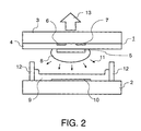
- the front panel 1 contains a glass plate 3 on which a dielectric layer 4 and a protective layer thereon 5 are applied.
- Parallel, strip-shaped discharge electrodes are on the glass plate 3 6.7 applied, which are covered by the dielectric layer 4.
- the discharge electrodes For example, 6.7 are made of metal or ITO.
- the carrier plate 2 is off Glass and on the carrier plate 2 are parallel, strip-shaped, perpendicular to the discharge electrodes 6.7 extending address electrodes 10 made of Ag, for example. These are from a phosphor layer 9, which emits light in one of the three primary colors, emitted green or blue, covered.
- the phosphor layer 9 is in several color segments divided. Usually the red, green or blue emitting color segments are the phosphor layer 9 applied in the form of vertical strip triplets.
- the individual plasma cells are preferably formed by a rib structure 12 with separating ribs dielectric material separated.
- a gas preferably a Noble gas mixture, for example from He, Ne or Kr with Xe as UV light generating Component.
- a plasma forms in the plasma area 8, depending on the composition radiation 11 in the UV range, in particular in the VUV range, is produced.
- This radiation 11 stimulates the fluorescent layer 9 to glow visible light 13 emitted in one of the three primary colors, which through the front panel 1 steps outwards and thus represents a luminous pixel on the screen.
- the front panel 1 of the plasma screen has a blue one on the side of the plasma cells Layer on.
- This can be either the dielectric layer 4, the protective layer 5 or one additional layer 14.
- the additional layer 14 is preferably on the Glass plate 3 and on the discharge electrodes 6.7. But it can also be between dielectric layer 4 and the protective layer 5 or between the glass plate and the Discharge electrodes 6.7 are located.
- the blue layer preferably contains colorant particles which are selected from the group CoAl 2 O 4 and the blue Ultramarine.
- the blue layer is to be the protective layer 5
- a layer of CoAl 2 O 4 with a layer thickness of 300 to 1500 nm is applied to the dielectric layer 4, which preferably contains PbO-containing glass. This can be done by vacuum evaporation of CoO and Al 2 O 3 or by wet chemical application of a CoAl 2 O 4 -containing suspension.
- the particle diameter of the CoAl 2 O 4 particles of such suspensions is preferably less than 200 nm.
- the blue layer can be produced from CoAl 2 O 4 by means of screen printing or other printing processes.
- the CoAl 2 O 4 -containing protective layer 5 is not applied over the entire surface of the dielectric layer 4, but structured.
- the CoAl 2 O 4 -containing protective layer 5 can be applied in a strip shape, parallel to the discharge electrodes 6, 7, on the dielectric layer 4.
- the area between two pairs of discharge electrodes 6, 7 in which no plasma discharge takes place is not covered with the protective layer 5 containing CoAl 2 O 4 .
- blue colorant particles are added to the starting material which is used to produce the dielectric layer 4.
- the starting material can be a glass material or a ceramic material.
- the dielectric layer 4 can be one or more oxides selected from the group Li 2 O, Na 2 O, K 2 O, SiO 2 , B 2 O 3 , BaO, Al 2 O 3 , ZnO, MgO, CaO and PbO mixed with CoAl 2 O 4 or Ultramarinen included.
- the particle size of the colorant particles is preferably between 20 and 5000 nm.
- a screen printing paste is first produced from equal parts by weight of the screen printing paste base and the glass material or the ceramic material.
- the screen printing paste base is preferably p- ment-1-en-8-ol with 5% by weight of ethyl cellulose.
- a colorant particle paste is produced from the screen printing paste base and 70 parts by weight of colorant particles.
- the screen printing paste is then mixed in a ratio of 10: 1 with the colorant particle paste.
- the paste obtained is applied by screen printing to the front plate 1, which has a glass plate 3 and discharge electrodes 6, 7.
- the dielectric layer 4 is dried and then the entire front plate 1 is exposed to a temperature of 485 ° C.
- the layer thickness of the finished dielectric layer 4 is preferably between 20 and 40 ⁇ m.
- the blue layer can be an additional layer 14.
- the blue layer can be an additional layer 14.
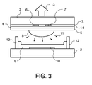
- Fig. 3 is a plasma screen with an additional Layer 14 shown, which on the glass plate 3 and on the discharge electrodes 6,7 is applied.
- a blue, additional layer 14 suspensions with colorant particles are first applied to the front plate 1 by means of a printing process, doctor blade process or spin coating process and then dried.
- the layer thickness of the blue, additional layer 14 is preferably between 0.1 and 2 ⁇ m.
- the blue, additional layer 14 can also be produced by means of known photolithographic processes or by means of vacuum evaporation of CoO and Al 2 O 3 .
- a suspension which is applied to the front plate 1 by means of spin coating preferably contains a low concentration of dissolved excipients, for example organic polymeric binders such as polyvinyl alcohol.
- the composition of the suspension of colorant particles is therefore advantageous to choose such that the dissolved proportions make up no more than 20 volume percent of the colorant particles. It is beneficial limit the volume ratio of colorant particles to binder to 10 to 1.
- a front plate 1 with a blue layer which is an additional layer 14
- 3 discharge electrodes 6, 7 made of ITO were applied to a glass plate.
- a suspension of CoAl 2 O 4 and polyvinyl alcohol in a ratio of 10: 1 was applied to the glass plate 3 and the discharge electrodes 6, 7 by means of spin coating.
- a blue, additional layer 14 of CoAl 2 O 4 with a layer thickness of 0.7 ⁇ m was obtained.
- a 700 nm thick protective layer 5 made of MgO was applied to the dielectric layer 4 by vacuum deposition.
- the front plate 1 was then used together with a carrier plate 2 and a xenon-containing gas mixture to build a plasma screen.
- the plasma screen had a color temperature of 8100 K. Furthermore, the luminance of the plasma screen was increased by 20 percent with the same contrast under ambient lighting.
- a screen printing paste made of 100 g p- menth-1-en-8-ol, which contained 5% by weight of ethyl cellulose, and 100 g of a glass material (T g ⁇ 475 ° C), which contained Li 2 O, Na 2 O, K 2 O, SiO 2 , B 2 O 3 , BaO, Al 2 O 3 , ZnO, MgO and CaO, and then dispersed them through two passes through a three-roll mill.
- the screen printing paste was in a dissolver with the paste with the colorant particle paste mixed in a ratio of 15: 1. After complete homogenization of the The resulting blue screen printing paste was mixed onto the front plate 1 of a plasma screen applied by screen printing. The layer obtained was dried and treated in an oven at 485 ° C. A transparent, blue dielectric was obtained Layer 4 35 ⁇ m thick. A 700 nm thick protective layer 5 of MgO layer applied to the dielectric layer 4. The front plate 1 was then together with a carrier plate 2 and one Xenon-containing gas mixture, used to build a plasma screen.
- a screen printing paste made of 100 g p- menth-1-en-8-ol, which contained 5% by weight of ethyl cellulose, and 100 g of a glass material (T g ⁇ 475 ° C), which contained Li 2 O, Na 2 O, K 2 O, SiO 2 , B 2 O 3 , BaO, Al 2 O 3 , ZnO, MgO and CaO, and then dispersed them through two passes through a three-roll mill.
- the screen printing paste was mixed in a dissolver with the colorant particle paste 10: 1 mixed. After the mixture had been completely homogenized, the blue screen printing paste obtained on the front plate 1 of a plasma screen Screen printing applied. The layer obtained was dried and placed in an oven 485 ° C treated. A transparent, blue dielectric layer 4 of 30 ⁇ m was obtained Thickness. A 700 nm thick protective layer 5 was removed by deposition in a vacuum MgO layer applied to the dielectric layer 4. Then the front panel 1 together with a carrier plate 2 and a xenon-containing gas mixture for Construction of a plasma screen used.
- aqueous suspension with a dispersant and 9.5% by weight of CoAl 2 O 4 was produced.
- the viscosity of the suspension was adjusted to 100 mPa * s using polyvinyl alcohol.
- the suspension was applied to the dielectric layer 4 of a front plate 1, which had a glass plate 3, a dielectric layer 4 and discharge electrodes 6, 7.
- the dielectric layer 4 contained PbO-containing glass and the two discharge electrodes 6, 7 were made of ITO.
- a 600 nm thick blue layer was obtained which also functioned as protective layer 5.
- the front plate 1 was then used together with a carrier plate 2 and a xenon-containing gas mixture to build a plasma screen.
- the white color point of the plasma screen was 7600 K.
- a colorant particle paste 100 g of p- menth-1-en-8-ol, which contained 5% by weight of ethyl cellulose, and 70 g of CoAl 2 O 4 were mixed. This paste was dispersed on a three-roll mill by two passes.
- the colorant particle paste was applied in strips to the dielectric layer 4 Front plate 1, which has a glass plate 3, discharge electrodes 6.7 and a dielectric Layer 4 had printed.
- the colorant particle paste was applied in such a way that a printed strip is structured in relation to a pair of discharge electrodes 6,7, between which a plasma discharge takes place.
- the distance between two printed strips was 30 ⁇ m and the layer thickness of one printed strip was 1.1 ⁇ m after drying.
- the dielectric layer 4 contained PbO-containing glass and the two discharge electrodes 6, 7 were made of ITO.
- the Front plate 1 together with a carrier plate 2 and a xenon-containing gas mixture, used to build a plasma screen.
- the white color point of the plasma screen was 7600 K.
- a 700 nm thick layer of CoAl 2 O 4 was applied to the dielectric layer 4 of a front plate 1, which had a glass plate 3, discharge electrodes 6, 7 and a dielectric layer 4, by means of electron beam evaporation of CoO and Al 2 O 3 in a high vacuum apparatus.
- the dielectric layer 4 contained PbO-containing glass and the two discharge electrodes 6, 7 were made of ITO.
- the front plate 1 was then used together with a carrier plate 2 and a xenon-containing gas mixture to build a plasma screen.
- the white color point of the plasma screen was 7600 K.
- (Y, Gd) BO 3 : Eu was used as the red-emitting phosphor
- Zn 2 SiO 4 : Mn was used as the green-emitting phosphor
- BaMgAl 10 O 17 Eu was used as the blue-emitting phosphor.
- the gas mixture contained 5% by volume of Xe and 95% by volume of Ne.
Landscapes
- Physics & Mathematics (AREA)
- Engineering & Computer Science (AREA)
- Plasma & Fusion (AREA)
- Gas-Filled Discharge Tubes (AREA)
Abstract
Description
- Fig 1
- den Aufbau und das Funktionsprinzip einer einzelnen Plasmazelle in einem AC-Plasmabildschirm,
- Fig 2
- den Aufbau und das Funktionsprinzip einer einzelnen Plasmazelle in einem AC-Plasmabildschirm mit einer blauen Schicht auf der Glasplatte und auf den Elektroden,
- Fig.3
- den Aufbau und das Funktionsprinzip einer einzelnen Plasmazelle in einem AC-Plasmabildschirm mit einer strukturierten blauen Schicht.
| Luminanz-Kontrast-Performance Gewinn (LCP Gewinn), Farbtemperatur, Weißfarbpunkt und Luminanz eines Plasmabildschirms in Abhängigkeit der Dicke einer Schutzschicht 5 aus CoAl2O4. | ||||
| Dicke [µm] | LCP Gewinn [%] | Farbtemperatur [K] | Weißfarbpunkt [x,y] | Luminanz [Cdm-2] |
| 0 | 0 | 5966 | 0.3227, 0.3324 | 379.5 |
| 0.173 | 2.6 | 6132 | 0.3193, 0.3327 | 341.7 |
| 0.272 | 3.8 | 6389 | 0.3146, 0.3301 | 332.2 |
| 0.487 | 6.8 | 7161 | 0.3024, 0.3227 | 305.4 |
| 0.728 | 9.7 | 8109 | 0.2901, 0.3153 | 282.1 |
| 1.570 | 15.3 | > 11000 | 0.2517, 0.2888 | 214.5 |
Claims (6)
- Plasmabildschirm ausgerüstet mit einer Frontplatte (1), die eine Glasplatte (3), auf der eine dielektrische Schicht (4) und eine Schutzschicht (5) aufgebracht sind, aufweist, mit einer Trägerplatte (2) ausgestattet mit einer Leuchtstoffschicht (9), mit einer Rippenstruktur (12), die den Raum zwischen Frontplatte (1) und Trägerplatte (2) in Plasmazellen, die mit einem Gas gefüllt sind, aufteilt, mit einem oder mehreren Elektroden-Arrays (6,7,10) auf der Frontplatte (1) und der Trägerplatte (2) zur Erzeugungvon stillen elektrischen Entladungen in den Plasmazellen, wobei die Frontplatte (1) auf der den Plasmazellen zugewandten Seite eine blaue Schicht aufweist.
- Plasmabildschirm nach Anspruch 1,
dadurch gekennzeichnet, dass die blaue Schicht die Schutzschicht (5) ist. - Plasmabildschirm nach Anspruch 2,
dadurch gekennzeichnet, dass sich die blaue Schicht strukturiert, parallel zu den Elektroden (6,7) auf der Frontplatte (1) befindet. - Plasmabildschirm nach Anspruch 1,
dadurch gekennzeichnet, dass die blaue Schicht die dielektrische Schicht (4) ist. - Plasmabildschirm nach Anspruch 1,
dadurch gekennzeichnet, dass die blaue Schicht auf der Glasplatte (3) und auf den Elektroden (6,7) der Frontplatte (1) aufgebracht ist. - Plasmabildschirm nach Anspruch 1,
dadurch gekennzeichnet, dass die blaue Schicht Farbmittel-Partikel ausgewählt aus der Gruppe CoAl2O4 und der blauen Ultramarine enthält.
Applications Claiming Priority (2)
| Application Number | Priority Date | Filing Date | Title |
|---|---|---|---|
| DE10122287 | 2001-05-08 | ||
| DE10122287A DE10122287A1 (de) | 2001-05-08 | 2001-05-08 | Plasmabildschirm mit verbessertem Weißfarbpunkt |
Publications (2)
| Publication Number | Publication Date |
|---|---|
| EP1258902A2 true EP1258902A2 (de) | 2002-11-20 |
| EP1258902A3 EP1258902A3 (de) | 2006-05-10 |
Family
ID=7683999
Family Applications (1)
| Application Number | Title | Priority Date | Filing Date |
|---|---|---|---|
| EP02100444A Withdrawn EP1258902A3 (de) | 2001-05-08 | 2002-05-06 | Plasmabildschirm mit verbessertem Weissfarbpunkt |
Country Status (7)
| Country | Link |
|---|---|
| US (1) | US6700324B2 (de) |
| EP (1) | EP1258902A3 (de) |
| JP (1) | JP2002358893A (de) |
| KR (1) | KR20020085807A (de) |
| CN (1) | CN1389893A (de) |
| DE (1) | DE10122287A1 (de) |
| TW (1) | TW584876B (de) |
Cited By (2)
| Publication number | Priority date | Publication date | Assignee | Title |
|---|---|---|---|---|
| EP1388878A1 (de) * | 2002-08-06 | 2004-02-11 | Fujitsu Limited | Substratanordnung für Gasentladungsanzeigevorrichtung |
| EP1643475A1 (de) * | 2004-09-30 | 2006-04-05 | Kabushiki Kaisha Toshiba | Anzeigevorrichtung und Anzeigeverfahren dafür |
Families Citing this family (1)
| Publication number | Priority date | Publication date | Assignee | Title |
|---|---|---|---|---|
| JP3942166B2 (ja) * | 2002-07-23 | 2007-07-11 | 株式会社日立プラズマパテントライセンシング | ガス放電パネルの基板構体の製造方法 |
Family Cites Families (4)
| Publication number | Priority date | Publication date | Assignee | Title |
|---|---|---|---|---|
| JP3145279B2 (ja) * | 1995-08-28 | 2001-03-12 | 大日本印刷株式会社 | プラズマディスプレイパネル及びその製造方法 |
| JPH1027550A (ja) * | 1996-05-09 | 1998-01-27 | Pioneer Electron Corp | プラズマディスプレイパネル |
| JP2000226229A (ja) * | 1999-02-04 | 2000-08-15 | Nippon Electric Glass Co Ltd | 誘電体形成材料及び誘電体形成ペースト |
| KR100432998B1 (ko) * | 1999-07-09 | 2004-05-24 | 삼성에스디아이 주식회사 | 플라즈마 디스플레이 패널 |
-
2001
- 2001-05-08 DE DE10122287A patent/DE10122287A1/de not_active Withdrawn
-
2002
- 2002-04-26 TW TW091108699A patent/TW584876B/zh not_active IP Right Cessation
- 2002-05-04 CN CN02141087A patent/CN1389893A/zh active Pending
- 2002-05-06 US US10/139,200 patent/US6700324B2/en not_active Expired - Fee Related
- 2002-05-06 EP EP02100444A patent/EP1258902A3/de not_active Withdrawn
- 2002-05-06 KR KR1020020024670A patent/KR20020085807A/ko not_active Withdrawn
- 2002-05-08 JP JP2002132801A patent/JP2002358893A/ja not_active Abandoned
Cited By (3)
| Publication number | Priority date | Publication date | Assignee | Title |
|---|---|---|---|---|
| EP1388878A1 (de) * | 2002-08-06 | 2004-02-11 | Fujitsu Limited | Substratanordnung für Gasentladungsanzeigevorrichtung |
| US7372206B2 (en) | 2002-08-06 | 2008-05-13 | Fujitsu Limited | Gas discharge panel substrate assembly having protective layer in contact with discharge space, and AC type gas discharge panel having the assembly |
| EP1643475A1 (de) * | 2004-09-30 | 2006-04-05 | Kabushiki Kaisha Toshiba | Anzeigevorrichtung und Anzeigeverfahren dafür |
Also Published As
| Publication number | Publication date |
|---|---|
| US20030038598A1 (en) | 2003-02-27 |
| US6700324B2 (en) | 2004-03-02 |
| TW584876B (en) | 2004-04-21 |
| JP2002358893A (ja) | 2002-12-13 |
| CN1389893A (zh) | 2003-01-08 |
| KR20020085807A (ko) | 2002-11-16 |
| EP1258902A3 (de) | 2006-05-10 |
| DE10122287A1 (de) | 2002-11-14 |
Similar Documents
| Publication | Publication Date | Title |
|---|---|---|
| DE69824034T2 (de) | Lumineszenzmittel, pulverförmiges lumineszenzmittel, plasma-anzeigetafel und herstellungsverfahren dersleben | |
| DE19534075C2 (de) | Phosphor | |
| EP1156507B1 (de) | Plasmabildschirm mit einem Terbium(III)-aktivierten Leuchtstoff | |
| DE10009915A1 (de) | Plasmabildschirm mit UV-Licht emittierender Schicht | |
| EP1215698B1 (de) | Plasmabildschirm mit Leuchtstoffschicht | |
| DE69910576T2 (de) | Herstellungsverfahren einer plasma-anzeigetafel zur erzielung gewisser lumineszenz eigenschaften | |
| EP1158559A2 (de) | Plasmabildschirm mit Terbium(III)-aktiviertem Leuchtstoff | |
| DE60127142T2 (de) | Plasmaschirm mit verbessertem Kontrast | |
| DE19962029A1 (de) | Plasmabildschirm mit rotem Leuchtstoff | |
| DE10009916A1 (de) | Plasmabildschirm mit blauem Leuchtstoff | |
| EP1187167B1 (de) | Farbbildschirm mit blauer Leuchtstoffschicht | |
| EP1258902A2 (de) | Plasmabildschirm mit verbessertem Weissfarbpunkt | |
| EP1296348A2 (de) | Plasmabildschirm mit erhöhter Effizienz | |
| DE602004010489T2 (de) | Plasma anzeigetafel | |
| EP1103591A1 (de) | Plasmabildschirm mit rotem Leuchtstoff | |
| DE60313312T2 (de) | Plasmaanzeigetafel enthaltend eine terbium(iii)-aktivierte fluoreszierende substanz | |
| DE602004010409T2 (de) | Plasmaanzeigetafel | |
| DE60316087T2 (de) | Plasma-Anzeigetafel mit grünem Leuchtstoff aus Aluminatmischung mit Spinelstruktur | |
| EP1229099A2 (de) | Plasmabildschirm mit einer Leuchtstoffschicht | |
| DE10215891A1 (de) | Plasmabildschirm mit erhöhter Effizienz | |
| DE3004535C2 (de) | Fluoreszierendes Material mit einem Gehalt an Indiumoxid | |
| DE60204724T2 (de) | Plasmabildschirm mit grünem phosphor | |
| DE10254175A1 (de) | Plasmabildschirm mit blauemittierendem Leuchtstoff | |
| DE19938355A1 (de) | Plasmabildschirm mit Reflexionsschicht | |
| DE10210043A1 (de) | Plasmabildschirm mit Pr(III)-aktiviertem Leuchtstoff |
Legal Events
| Date | Code | Title | Description |
|---|---|---|---|
| PUAI | Public reference made under article 153(3) epc to a published international application that has entered the european phase |
Free format text: ORIGINAL CODE: 0009012 |
|
| AK | Designated contracting states |
Kind code of ref document: A2 Designated state(s): AT BE CH CY DE DK ES FI FR GB GR IE IT LI LU MC NL PT SE TR |
|
| AX | Request for extension of the european patent |
Free format text: AL;LT;LV;MK;RO;SI |
|
| RAP1 | Party data changed (applicant data changed or rights of an application transferred) |
Owner name: KONINKLIJKE PHILIPS ELECTRONICS N.V. Owner name: PHILIPS INTELLECTUAL PROPERTY & STANDARDS GMBH |
|
| PUAL | Search report despatched |
Free format text: ORIGINAL CODE: 0009013 |
|
| AK | Designated contracting states |
Kind code of ref document: A3 Designated state(s): AT BE CH CY DE DK ES FI FR GB GR IE IT LI LU MC NL PT SE TR |
|
| AX | Request for extension of the european patent |
Extension state: AL LT LV MK RO SI |
|
| RIC1 | Information provided on ipc code assigned before grant |
Ipc: H01J 17/49 20060101AFI20020927BHEP |
|
| RAP1 | Party data changed (applicant data changed or rights of an application transferred) |
Owner name: KONINKLIJKE PHILIPS ELECTRONICS N.V. Owner name: PHILIPS INTELLECTUAL PROPERTY & STANDARDS GMBH |
|
| AKX | Designation fees paid | ||
| STAA | Information on the status of an ep patent application or granted ep patent |
Free format text: STATUS: THE APPLICATION IS DEEMED TO BE WITHDRAWN |
|
| 18D | Application deemed to be withdrawn |
Effective date: 20061201 |
|
| REG | Reference to a national code |
Ref country code: DE Ref legal event code: 8566 |