EP0043673A2 - Schneiddraht-Funkenerosionsmaschine - Google Patents
Schneiddraht-Funkenerosionsmaschine Download PDFInfo
- Publication number
- EP0043673A2 EP0043673A2 EP81302844A EP81302844A EP0043673A2 EP 0043673 A2 EP0043673 A2 EP 0043673A2 EP 81302844 A EP81302844 A EP 81302844A EP 81302844 A EP81302844 A EP 81302844A EP 0043673 A2 EP0043673 A2 EP 0043673A2
- Authority
- EP
- European Patent Office
- Prior art keywords
- wire
- cut
- broken
- feed
- auxiliary
- Prior art date
- Legal status (The legal status is an assumption and is not a legal conclusion. Google has not performed a legal analysis and makes no representation as to the accuracy of the status listed.)
- Granted
Links
Images
Classifications
-
- B—PERFORMING OPERATIONS; TRANSPORTING
- B23—MACHINE TOOLS; METAL-WORKING NOT OTHERWISE PROVIDED FOR
- B23H—WORKING OF METAL BY THE ACTION OF A HIGH CONCENTRATION OF ELECTRIC CURRENT ON A WORKPIECE USING AN ELECTRODE WHICH TAKES THE PLACE OF A TOOL; SUCH WORKING COMBINED WITH OTHER FORMS OF WORKING OF METAL
- B23H7/00—Processes or apparatus applicable to both electrical discharge machining and electrochemical machining
- B23H7/02—Wire-cutting
- B23H7/08—Wire electrodes
- B23H7/10—Supporting, winding or electrical connection of wire-electrode
Definitions
- the present invention relates to a wire-cut, electric discharge machine .
- a pulse-like voltage is applied across a wire installed on a wire running system and a work to produce therebetween a discharge, by which the work is cut into an arbitrary shape.
- the wire may be broken in the work during cutting unless the cutting conditions, the tension of the wire, the wire take-up speed and so forth are appropriate.
- breakage of the wire it is general practice in the prior art to re-install the wire by manual operation but this is very troublesome and cuts down the efficiency of the cutting operation. To avoid this, there is a strong demand for automating the re-installation of the wire.
- a wire-cut, electric discharge machine which is operable to cut a work into an arbitrary configuration by a discharge between the work and a wire installed on a wire running system of the machine when it is in use, the machine comprising:
- An embodiment of the present invention may provide a wire-cut, electric discharge machine which is designed so that a cut or broken end of a wire can be positioned at a predetermined position.
- An embodiment of the present invention may provide a wire-cut, electric discharge machine which is adapted to be capable of automatically reinstalling a wire in case of its breakage.
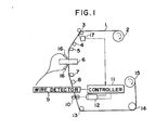
- Fig. 1 shows a wire-cut electric discharge machine.
- the auxiliary wire feed rollers 10 are held out of contact with the wire 1 during normal cutting but, in case of breakage of the wire 1, they grip therebetween the wire 1.
- the wire 1 When the wire 1 is broken during machining, its tension is reduced to zero to turn OFF the limit switch 17, by which the controler 11 detects the breakage of the wire 1.
- the controller 11 drives the motor 12 to rotate the auxiliary wire feed rollers 10, feeding the wire 1 downwardly.
- the wire detector 9 applies a detection signal to the controller 11 to stop the motor 12, thus stopping the auxiliary wire feed rollers 10 from rotating. In consequence, the feed of the wire 1 is stopped, so that the end of the broken wire 1 is positioned at a predetermined position, i.e. at the position of the wire detector 9. Accordingly, even when the wire 1 is broken during cutting, its broken end is brought to such a predetermined position; therefore, the wire 1 can automatically be reinstalled.
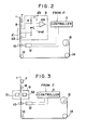
- Fig. 2 illustrates an example of the arrangement of the wire detector 9.
- Reference numeral 21 indicates a wire detecting brush; 22 designates a feed pin for detecting the wire; 23 identifies a power source; 24 denotes a voltage comparator; R represents a resistor; and C shows a capacitor.
- the other parts corresponding to those in F ig. 1 are identified by the same reference numerals.
- the voltage comparator 24 provides an output "1" or "0" depending on whether it is supplied with a voltage higher or lower than a reference voltage Vref.
- the controller 11 drives the motor 12 to rotate the auxiliary wire feed rollers 10, feeding the wire 1 downwardly, as described previously in regard to Fig. 1. While the wire 1 is in contact with the wire detecting brush 21, the voltage applied to the voltage comparator 24 is lower than the reference voltage Vref, so that the output from the voltage comparator 24 is "0". When the wire 1 is drawn away from the wire detecting brush 21, that is, when the wire 1 is moved out of contact with the wire detecting brush 21, the voltage applied to the voltage comparator 24 becomes higher than the reference voltage Vref, so that the voltage comparator 24 produces the output "1". Upon detection of this output, the controller 11 stops the motor 12, stopping the rotation of the auxiliary wire feed rollers 10. By this, the feed of the wire 1 is stopped, positioning its broken end at the predetermined location.
- Fig. 3 illustrates another example of the arrangement of the wire detector 9.
- Reference numeral 31 indicates a light emitting element such as a light emitting diode; and 32 designates a photo detector such as a photo transistor.
- the other parts corresponding to those in Fig. 1 are marked with the same reference numerals.
- the controller 11 drives the motor 12 to rotate the auxiliary wire feed rollers 10, feeding the wire 1 downwardly, as described previously.
- the extreme end or the broken end of the wire 1 passes between the light emitting element 31 and the photo detector 32, light from the light emitting element 31 is incident on the photo detector 32, which applies a detection signal to the controller 11.
- the controller 11 stops the motor 12 to stop the auxiliary wire feed rollers 10 from rotating.
- the feed of the wire 1 is stopped, positioning its end at the predetermined position.
- the present 9 embodimeitis provided with the wire detector by which, when the wire is broken, the extreme end of the broken wire fed in a backward direction by the auxiliary wire feed means composed of the auxiliary wire feed rollers 10, the controller 11 and the motor 12 is detected at the predetermined position. There is applied the detection signal to the auxiliary wire feed means, which stops the feed of the wire by the auxiliary wire feed means, so that the broken end of the broken wire can be positioned at the predetermined position. Accordingly, even if the wire is broken during cutting, it can automatically be reinstalled.
Landscapes
- Chemical & Material Sciences (AREA)
- Chemical Kinetics & Catalysis (AREA)
- Electrochemistry (AREA)
- Engineering & Computer Science (AREA)
- Mechanical Engineering (AREA)
- Electrical Discharge Machining, Electrochemical Machining, And Combined Machining (AREA)
- Forwarding And Storing Of Filamentary Material (AREA)
- Filamentary Materials, Packages, And Safety Devices Therefor (AREA)
Applications Claiming Priority (2)
| Application Number | Priority Date | Filing Date | Title |
|---|---|---|---|
| JP89386/80 | 1980-06-30 | ||
| JP55089386A JPS6052893B2 (ja) | 1980-06-30 | 1980-06-30 | ワイヤカツト放電加工機 |
Publications (3)
| Publication Number | Publication Date |
|---|---|
| EP0043673A2 true EP0043673A2 (de) | 1982-01-13 |
| EP0043673A3 EP0043673A3 (en) | 1983-01-05 |
| EP0043673B1 EP0043673B1 (de) | 1984-11-07 |
Family
ID=13969218
Family Applications (1)
| Application Number | Title | Priority Date | Filing Date |
|---|---|---|---|
| EP81302844A Expired EP0043673B1 (de) | 1980-06-30 | 1981-06-24 | Schneiddraht-Funkenerosionsmaschine |
Country Status (4)
| Country | Link |
|---|---|
| US (1) | US4412118A (de) |
| EP (1) | EP0043673B1 (de) |
| JP (1) | JPS6052893B2 (de) |
| DE (1) | DE3167059D1 (de) |
Cited By (3)
| Publication number | Priority date | Publication date | Assignee | Title |
|---|---|---|---|---|
| US4862095A (en) * | 1984-05-30 | 1989-08-29 | Mitsubushi Denki Kabushiki Kaisha | Wire electrode breakage detection method and apparatus |
| EP0585713A1 (de) * | 1992-08-26 | 1994-03-09 | AG für industrielle Elektronik AGIE Losone bei Locarno | Elektroerosions-Schneidvorrichtung und -verfahren |
| CN106297176A (zh) * | 2016-10-26 | 2017-01-04 | 国家电投集团西安太阳能电力有限公司 | 线切机主轴报警装置及对应的切线机 |
Families Citing this family (19)
| Publication number | Priority date | Publication date | Assignee | Title |
|---|---|---|---|---|
| US4689462A (en) * | 1984-03-05 | 1987-08-25 | Brother Kogyo Kabushiki Kaisha | Wire cutting type electrical discharge machining system |
| JPS629827A (ja) * | 1985-07-04 | 1987-01-17 | Fanuc Ltd | ワイヤカツト放電加工方法と装置 |
| JPS6219327A (ja) * | 1985-07-19 | 1987-01-28 | Fanuc Ltd | ワイヤカツト放電加工装置 |
| JPS6239127A (ja) * | 1985-08-13 | 1987-02-20 | Fanuc Ltd | ワイヤ放電加工機のワイヤ送り出し装置 |
| JPS6263019A (ja) * | 1985-09-13 | 1987-03-19 | Fanuc Ltd | 自動結線終了検出装置 |
| JPS6263018A (ja) * | 1985-09-14 | 1987-03-19 | Fanuc Ltd | ワイヤカツト放電加工機におけるワイヤ電極断線位置検出方法 |
| JP2577579B2 (ja) * | 1987-10-27 | 1997-02-05 | ファナック株式会社 | ワイヤ断線検出装置 |
| JPH0197830U (de) * | 1987-12-16 | 1989-06-29 | ||
| JPH01205933A (ja) * | 1988-02-08 | 1989-08-18 | Fanuc Ltd | ワイヤ送り装置 |
| JP2573514B2 (ja) * | 1988-05-11 | 1997-01-22 | ファナック株式会社 | ワイヤ断線位置検出装置 |
| JPH0253529A (ja) * | 1988-08-16 | 1990-02-22 | Mitsubishi Electric Corp | ワイヤ放電加工装置のワイヤ電極供給装置 |
| JPH08335B2 (ja) * | 1988-09-14 | 1996-01-10 | 三菱電機株式会社 | ワイヤ放電加工装置 |
| JP2979755B2 (ja) * | 1991-08-12 | 1999-11-15 | ブラザー工業株式会社 | ワイヤ放電加工機のワイヤ巻上制御装置 |
| JP3084880B2 (ja) * | 1992-01-27 | 2000-09-04 | ブラザー工業株式会社 | ワイヤ放電加工機におけるワイヤ電極の切断装置 |
| ES1027059Y (es) * | 1994-02-15 | 1995-01-16 | Ona Electro Erosion | Dispositivo de enhebrado automatico para maquina de electroerosion por hilo. |
| GB2318536B (en) * | 1996-10-23 | 1999-10-13 | Ona Electro Erosion | Automatic cutting and threading procedure and mechanism for an electroerosion machine |
| DE10061691B4 (de) | 2000-12-12 | 2004-12-30 | Agie S.A., Losone | Vorrichtung und Verfahren zur Detektion einer Bearbeitungselektrode einer Werkzeugmaschine |
| JP5128012B1 (ja) * | 2012-01-27 | 2013-01-23 | 三菱電機株式会社 | ワイヤ放電加工機及びワイヤ電極除去装置 |
| CN112498790B (zh) * | 2020-10-12 | 2022-08-16 | 河钢股份有限公司承德分公司 | 一种上线系统断线保护装置和打捆机 |
Family Cites Families (6)
| Publication number | Priority date | Publication date | Assignee | Title |
|---|---|---|---|---|
| CH534563A (de) * | 1970-12-16 | 1973-03-15 | Gavrilovich Semin Gennady | Einrichtung zur automatischen Stillsetzung einer Elektroerosionsmaschine bei Bruch des Werkzeuges |
| US3987270A (en) * | 1973-08-15 | 1976-10-19 | A.G. Fur Industrielle Elektronik Agie Losone B. Locarno | Automatic set-up electroerosion machining method and apparatus |
| DE2755777C2 (de) * | 1977-12-14 | 1983-12-01 | Siemens AG, 1000 Berlin und 8000 München | Verfahren und Vorrichtung zum automatischen Schnittstellen-Wechsel bei der elektroerosiven Bearbeitung mit draht- oder bandförmiger Elektrode |
| US4233486A (en) * | 1977-12-26 | 1980-11-11 | Inoue-Japax Research Incorporated | Traveling-wire electrical discharge machine |
| CH625447A5 (de) * | 1978-03-06 | 1981-09-30 | Agie Ag Ind Elektronik | |
| JPS5927298B2 (ja) * | 1979-06-15 | 1984-07-04 | ファナック株式会社 | ワイヤカット放電加工機 |
-
1980
- 1980-06-30 JP JP55089386A patent/JPS6052893B2/ja not_active Expired
-
1981
- 1981-06-10 US US06/272,190 patent/US4412118A/en not_active Expired - Fee Related
- 1981-06-24 DE DE8181302844T patent/DE3167059D1/de not_active Expired
- 1981-06-24 EP EP81302844A patent/EP0043673B1/de not_active Expired
Cited By (5)
| Publication number | Priority date | Publication date | Assignee | Title |
|---|---|---|---|---|
| US4862095A (en) * | 1984-05-30 | 1989-08-29 | Mitsubushi Denki Kabushiki Kaisha | Wire electrode breakage detection method and apparatus |
| EP0585713A1 (de) * | 1992-08-26 | 1994-03-09 | AG für industrielle Elektronik AGIE Losone bei Locarno | Elektroerosions-Schneidvorrichtung und -verfahren |
| US5434379A (en) * | 1992-08-26 | 1995-07-18 | A.G. fur Industrielle Elektronik AGIE Losone | Apparatus for and method of electro-discharge cutting |
| CN106297176A (zh) * | 2016-10-26 | 2017-01-04 | 国家电投集团西安太阳能电力有限公司 | 线切机主轴报警装置及对应的切线机 |
| CN106297176B (zh) * | 2016-10-26 | 2018-08-17 | 国家电投集团西安太阳能电力有限公司 | 线切机主轴报警装置及对应的线切机 |
Also Published As
| Publication number | Publication date |
|---|---|
| JPS6052893B2 (ja) | 1985-11-21 |
| JPS5715634A (en) | 1982-01-27 |
| EP0043673B1 (de) | 1984-11-07 |
| US4412118A (en) | 1983-10-25 |
| DE3167059D1 (en) | 1984-12-13 |
| EP0043673A3 (en) | 1983-01-05 |
Similar Documents
| Publication | Publication Date | Title |
|---|---|---|
| EP0043673B1 (de) | Schneiddraht-Funkenerosionsmaschine | |
| US5209414A (en) | Apparatus for precisely winding a coil of wire | |
| US4233486A (en) | Traveling-wire electrical discharge machine | |
| US4667078A (en) | Apparatus for guiding a wire or strip-like cutting electrode on a machine tool | |
| KR100407765B1 (ko) | 권취장치 | |
| US5019684A (en) | Wire disconnection position detecting apparatus | |
| KR910007362B1 (ko) | 와이어 방전 가공기의 와이어 송출기구 | |
| US5219124A (en) | Multi-phase synchronous automatic winding method and apparatus for motor stators | |
| US5268551A (en) | Wire electrode positioning control device of electrical discharge wire-cutting machine | |
| US3837589A (en) | Apparatus and method for continuous spooling | |
| EP0581493A1 (de) | Verfahren und Ausrüstung für den automatischen Übergang des zugeführten Drahtes in einer Funkenerosionsmaschine | |
| US4907343A (en) | Terminal dereeling apparatus | |
| US2903557A (en) | Arc machining with band electrode | |
| US4486642A (en) | Electroerosive contour-machining method | |
| US2997017A (en) | Waxing attachment for winding machines | |
| US3952591A (en) | Machine for cleaning and inspecting motion picture films | |
| DE69806712T2 (de) | Arbeitsunterbrechungsverarbeitungssystem für eine Garnaufwickelmaschine | |
| CN210103118U (zh) | 涤纶短纤维自动换卷装置 | |
| JPH0970824A (ja) | ワイヤソーのワイヤ脱線検出装置 | |
| JPS62146661A (ja) | ラベルプリンタ | |
| US11155431B2 (en) | Winding machine for web-type materials and method for operating such a winding machine | |
| JP2000190196A (ja) | ワイヤソ―のリ―ルボビンの異常回転検知構造 | |
| CN110605443A (zh) | 线放电加工机以及加工条件调整方法 | |
| JPH1086141A (ja) | ワイヤソー | |
| JP7700002B2 (ja) | 部品供給フィーダ、それを備える部品実装機、及び基板の製造方法。 |
Legal Events
| Date | Code | Title | Description |
|---|---|---|---|
| PUAI | Public reference made under article 153(3) epc to a published international application that has entered the european phase |
Free format text: ORIGINAL CODE: 0009012 |
|
| AK | Designated contracting states |
Designated state(s): CH DE FR GB LI |
|
| RBV | Designated contracting states (corrected) |
Designated state(s): CH DE FR GB LI |
|
| RAP1 | Party data changed (applicant data changed or rights of an application transferred) |
Owner name: FANUC LIMITED |
|
| PUAL | Search report despatched |
Free format text: ORIGINAL CODE: 0009013 |
|
| AK | Designated contracting states |
Designated state(s): CH DE FR GB LI |
|
| 17P | Request for examination filed |
Effective date: 19830406 |
|
| GRAA | (expected) grant |
Free format text: ORIGINAL CODE: 0009210 |
|
| AK | Designated contracting states |
Designated state(s): CH DE FR GB LI |
|
| REF | Corresponds to: |
Ref document number: 3167059 Country of ref document: DE Date of ref document: 19841213 |
|
| ET | Fr: translation filed | ||
| RAP2 | Party data changed (patent owner data changed or rights of a patent transferred) |
Owner name: FANUC LTD |
|
| REG | Reference to a national code |
Ref country code: CH Ref legal event code: PFA Free format text: FANUC LIMITED |
|
| REG | Reference to a national code |
Ref country code: FR Ref legal event code: CA |
|
| PLBE | No opposition filed within time limit |
Free format text: ORIGINAL CODE: 0009261 |
|
| STAA | Information on the status of an ep patent application or granted ep patent |
Free format text: STATUS: NO OPPOSITION FILED WITHIN TIME LIMIT |
|
| 26N | No opposition filed | ||
| PGFP | Annual fee paid to national office [announced via postgrant information from national office to epo] |
Ref country code: FR Payment date: 19910529 Year of fee payment: 11 |
|
| PGFP | Annual fee paid to national office [announced via postgrant information from national office to epo] |
Ref country code: GB Payment date: 19910611 Year of fee payment: 11 |
|
| PG25 | Lapsed in a contracting state [announced via postgrant information from national office to epo] |
Ref country code: GB Effective date: 19920624 |
|
| GBPC | Gb: european patent ceased through non-payment of renewal fee |
Effective date: 19920624 |
|
| PG25 | Lapsed in a contracting state [announced via postgrant information from national office to epo] |
Ref country code: FR Effective date: 19930226 |
|
| REG | Reference to a national code |
Ref country code: FR Ref legal event code: ST |
|
| PGFP | Annual fee paid to national office [announced via postgrant information from national office to epo] |
Ref country code: CH Payment date: 19930628 Year of fee payment: 13 |
|
| PGFP | Annual fee paid to national office [announced via postgrant information from national office to epo] |
Ref country code: DE Payment date: 19930630 Year of fee payment: 13 |
|
| PG25 | Lapsed in a contracting state [announced via postgrant information from national office to epo] |
Ref country code: LI Effective date: 19940630 Ref country code: CH Effective date: 19940630 |
|
| REG | Reference to a national code |
Ref country code: CH Ref legal event code: PL |
|
| PG25 | Lapsed in a contracting state [announced via postgrant information from national office to epo] |
Ref country code: DE Effective date: 19950301 |