EP0035238A1 - Machine de lavage et/ou de remplissage de récipients - Google Patents
Machine de lavage et/ou de remplissage de récipients Download PDFInfo
- Publication number
- EP0035238A1 EP0035238A1 EP81101384A EP81101384A EP0035238A1 EP 0035238 A1 EP0035238 A1 EP 0035238A1 EP 81101384 A EP81101384 A EP 81101384A EP 81101384 A EP81101384 A EP 81101384A EP 0035238 A1 EP0035238 A1 EP 0035238A1
- Authority
- EP
- European Patent Office
- Prior art keywords
- treatment
- container
- cleaning
- media
- head
- Prior art date
- Legal status (The legal status is an assumption and is not a legal conclusion. Google has not performed a legal analysis and makes no representation as to the accuracy of the status listed.)
- Granted
Links
Images

Classifications
-
- B—PERFORMING OPERATIONS; TRANSPORTING
- B67—OPENING, CLOSING OR CLEANING BOTTLES, JARS OR SIMILAR CONTAINERS; LIQUID HANDLING
- B67C—CLEANING, FILLING WITH LIQUIDS OR SEMILIQUIDS, OR EMPTYING, OF BOTTLES, JARS, CANS, CASKS, BARRELS, OR SIMILAR CONTAINERS, NOT OTHERWISE PROVIDED FOR; FUNNELS
- B67C3/00—Bottling liquids or semiliquids; Filling jars or cans with liquids or semiliquids using bottling or like apparatus; Filling casks or barrels with liquids or semiliquids
- B67C3/30—Filling of barrels or casks
-
- B—PERFORMING OPERATIONS; TRANSPORTING
- B08—CLEANING
- B08B—CLEANING IN GENERAL; PREVENTION OF FOULING IN GENERAL
- B08B9/00—Cleaning hollow articles by methods or apparatus specially adapted thereto
- B08B9/08—Cleaning containers, e.g. tanks
- B08B9/0804—Cleaning containers having tubular shape, e.g. casks, barrels, drums
Definitions
- the invention relates to a method for cleaning and / or filling containers by supplying the liquid or gaseous media through an end valve of the container via at least one treatment head.
- a cylindrical barrel with a centrally arranged valve on the front is increasingly being used as a rational packaging for liquids.
- This type of packaging is known as KEG in the English-speaking world. This designation was also adopted in the German-speaking area.
- the KEG is primarily used for storage and as a transport container for beer and soft drinks.
- machines For the semi-automatic or fully automatic cleaning and filling of the KEG, machines are used that work in cycles, in which the KEG is placed one after the other on one of several treatment heads arranged in a row or in a circle such that e.g. on the first head the beverage residue is expelled and a pre-cleaning takes place.
- the KEG is then lifted off this treatment head in order to be placed on the next one, via which a further pre-cleaning or a main cleaning with washing liquid is carried out.
- the KEG is cleaned, sterilized on another and finally lifted onto the next head for pre-loading and filling.
- Breweries which operate 15 of the machines described above in parallel, i.e. operate with treatment heads connected in parallel to the media supply and discharge lines and intended for the same work step.
- This inevitably brings with it several disadvantages in the supply of the media, including the contents, especially in the case of carbonated beverages, that is to say also in the case of beer.
- the supply can periodically drop to almost zero and then increase in a short time to 15 times the amount required for a single KEG, e.g. all filling valves are open at the same time.
- a total of 15 x 25 a total of approx. 375 media valves are calculated for the operation of an entire system with machines working in parallel, which are operated with a considerable amount of control, but also require maintenance.
- a method and a device are now proposed according to the invention with which it is possible to fill containers, in particular cylindrical containers such as KEGs, with increased throughput without the need to connect several cleaning and filling machines in parallel, at least with one such Filling and cleaning performance, such as was achieved in the same time only by connecting several machines in parallel according to the previously used processes.
- the invention is therefore particularly applicable to all filling and cleaning processes on containers such as KEGs with great advantage, in which, according to previous technology, at least two container cleaning and filling systems had to be operated in parallel.
- the containers run e.g. on a rotationally symmetrical path around an axis.
- the operations can be controlled in such a way that each operation a) to g) is assigned a specific sector of this path. Since the individual operations can take different times, it is quite possible that several containers subjected to the process in succession are going through one and the same treatment sector, for example the operation in question in one container is almost completed, while in the next container the same operation is in progress is just beginning. Thus, by exposing the individual containers one after the other in time to the essentially same sequence of operations, an increased throughput can be achieved without having to subject several containers to the same treatment operations in parallel.
- the five operations a) to e) and optionally f) are carried out in such a way that the treatment head is not separated from the container during these operations; they are therefore carried out via the same treatment head.
- external cleaning can also be carried out simultaneously with at least one working step of the internal cleaning.
- the container with the respectively assigned treatment head is moved as a unit for carrying out at least two of the work steps a) to g) to different work positions or areas, in which work positions or areas the respective container is moved then the necessary media for carrying out the upcoming work step are fed.
- the movement of the container with the treatment head is expediently carried out continuously in order to increase the throughput, as a result of which the throughput achievable with the invention can be increased still further.
- the invention also relates to a device for carrying out the method described in more detail above.
- Such a device is characterized in particular by the fact that the treatment heads are arranged at defined intervals from one another and can be moved on a path and can be connected to the media inlets and outlets one after the other.
- the treatment heads are arranged on a rotationally symmetrical path, in particular on a circular path.
- a control mechanism can be provided in a further embodiment, which causes the media inlets and / or outlets to be blocked as long as there is no fixed connection between the container and the treatment head.
- an additional device for temperature measurement is provided on the outside of containers and / or of media inlets and / or outlets. Disruptions in the course of the process can be determined hereby. If e.g. for some reason supply lines for the hot liquor are blocked, this can be determined by measuring the temperature of the outer wall of the container at the appropriate point.
- the additional temperature measuring device can also be used, for example, to determine or check the correct point in time after the sterilization of the respective container by means of steam, at which the filling process can be started.
- such an additional device is not only suitable for carrying out the method according to the invention in connection with the device described in more detail above, but also independently for other methods and devices for cleaning and / or filling containers.
- the method of operation according to the invention i.a. also has the advantage that the wear of the fitting seals and the seals on the filling heads is greatly reduced. This increases operational safety considerably because the number of possible occasions for operational malfunctions, e.g. due to the fewer transfer operations of the containers to the individual treatment heads. due to centering errors or difficulties.
- the electrical control of the cleaning cycle and in particular the mechanical process is simplified considerably, since a significantly smaller number of valves is required.
- a cleaning and / or filling method for containers is therefore proposed which allows the same throughput to be achieved with a significantly lower outlay on equipment or a substantially higher throughput with the same outlay on equipment.
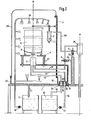
- Fig. I shows a partial section of the advantageous, but by no means necessary embodiment, in which an external cleaning can be carried out simultaneously with the internal cleaning, which has not previously been used in systems with parallel connection of two or more cleaning and filling machines of the usual type because it is uneconomical was.
- each of the cleaning and filling machines connected in parallel should have been assigned a special system for external cleaning.
- the device according to the invention as shown in FIG. I, is provided with a covering 26. This makes it possible to save a separate machine for external cleaning.
- FIG. I has a stator 1 designed as a table, a rotor 2 on which a treatment head 3 and a spring-loaded, lowerable KEG receiving plate 4 are arranged so as to be rotatable therewith.
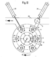
- the rotor 2 rotates about a vertical axis A and is shown schematically in plan view in FIG. II.
- a valve 6 arranged in a certain circumferential position and rotating with the rotor 2 is actuated by passing a correspondingly designed fixed cam 33, whereby the KEG 5 with its end valve 8 against the action of springs is connected to a pressure medium line 30 via a cylinder 7 27 is lowered onto the treatment head 3.
- a pin (not shown), which opens the valve 8 of the KEG 5, is actuated via a valve 9, which also rotates with the rotor 2, by means of a second fixed cam 34 and via a pressure medium line 28.
- the pressure medium lines 28, 30 are fed from a rotary distributor 25 rotatable with the rotor 2.
- the rotor 2 is equipped with a distributor disk 10, which has openings 16 in radial spacing and which appears schematically in FIG. II in plan view.
- a distributor disk 10 which has openings 16 in radial spacing and which appears schematically in FIG. II in plan view.
- different media can be fed through this distributor disk 10 to the KEG 5 in certain circulation sectors via an angle distributor 11, which is firmly connected to the stator 1, that is, for example, first compressed air for expelling the beverage residue from the previous one Filling of the KEG 5, as well as further spray water, then cleaning liquid, by feeding the respective media from a container 12 to the KEG 5 from a container 12 via a pump 13, the line 14, 14 ', sector-shaped slots 31 assigned to the openings 16. The return takes place via a line 15 ', 15 and the other hole-opening pair 16, 31 back into the container 12.
- FIG. II schematically shows the rotor 2 in plan view with a number of treatment heads 3 which can be rotated with the rotor 2, the number shown being chosen arbitrarily.
- Media is supplied or discharged to the treatment head 3 during rotation in certain sectors via the distributor disc 10 with openings 16, as long as the respective opening 16 overlap with the respectively assigned sector slots 31 of the angle distributor 11, of which (dashed) for example, only one pair is shown.
- the KEGs 5 are pushed onto the individual finished, lowerable KEG receptacles 4 via a conveyor track 23 by means of a slide 24.
- the treatment of the KEG 5 described in connection with FIG. 1 takes place, which is then drawn back onto the transport path 23 by a device 20 after the end of the treatment and is transported further in the direction of the arrow C.
- Fig. III shows the example of a device in which only pre-stressed and filled.
- the stator 1 and the rotor 2, on which a treatment head 3 and a sprung, lowerable KEG receptacle 4 is arranged, are formed similarly to Fig. I.
- the rotor 2 is again rotatable about the axis A.
- a schematic plan view of this rotor 2 is also shown in FIG. II.
- valve 6 arranged in a certain circumferential position is first actuated by moving past an appropriately designed, fixed cam 33, whereby the KEG 5 is also actuated via the cylinder 7 actuated by the pressure medium line 30 its valve 8 is lowered against the action of the springs 27 on the treatment head 3. Then, via the valve 9 located in the pressure medium line 28 and cooperating with the fixed cam 34, a pin (not shown in the treatment head 3) is actuated, which opens the valve 8.
- the rotor 2 is also equipped with a perforated distributor disk 10, as can be seen in FIG. II.
- various media can be supplied to the KEG 5 in certain sectors through the openings 16 contained in the distributor disk 10, via the angular distributor 11 equipped with corresponding sector-shaped slots 31, which is firmly connected to the stator 1, such as bias gas via the line 14, 14 'and then by opening a filler valve (not shown) in the treatment head 3, the beverage liquid via the rotary distributors 25 rotatable with the rotor 2 and a line 32.
- a check valve 26 initiates the closing of the filler valve (not shown) in the treatment head 3 and again via the line 14, 14 'in the treatment head 3 residual filling material via the line 15, 15', the distributor disk 10 and the angle distributor 11 blown out.
- I and III have a control mechanism (not shown) which ensures that the valves in the media supply and discharge lines block as long as the KEG 5 and treatment head 3 are not firmly and tightly coupled to one another.
- An additional device (not shown) can also be provided, with the aid of which temperature control measurements can be carried out on the outside of the KEG 5 or the media supply and discharge lines.
- Such an additional device is particularly useful if the operations a) to e) mentioned in the introduction are carried out in a device according to the invention and the operations f) and g) are carried out in a second device according to the invention.
- the KEG 5, which has just been sterilized by steam and therefore still filled with steam, can then be transported from the first treatment device via a transport path to the second treatment device and checked immediately before entering the second treatment device with regard to the outside temperature of the KEG 5, so that the point in time , which can be started with preloading and filling, can be determined with certainty.
- distributor disk 10 and angle distributor 11 lie concentrically on top of one another as disk rings and each have pairs of openings 16 or slot pairs 31 at a radial spacing, that is to say the media are fed in and discharged via the same distributor disk and angle distributor combination, for example the media feed and discharge are each placed in separate distributor disks 10 and angle distributors 11.
- the distributor disk-angle distributor combination shown in FIG. I between the respective two openings 16 and slots 31 divided vertically, whereby two pairs of rings are formed which are at the same radial distance from the axis A and at an axial distance above one another, possibly with reversal can be arranged from the top and bottom with appropriately modified cable routing.
- FIG. III The same variant is possible in the device according to FIG. III.
Landscapes
- Engineering & Computer Science (AREA)
- Mechanical Engineering (AREA)
- Filling Of Jars Or Cans And Processes For Cleaning And Sealing Jars (AREA)
Priority Applications (1)
| Application Number | Priority Date | Filing Date | Title |
|---|---|---|---|
| AT81101384T ATE22431T1 (de) | 1980-03-04 | 1981-02-25 | Vorrichtung zur reinigung und/oder fuellung von behaeltern. |
Applications Claiming Priority (2)
| Application Number | Priority Date | Filing Date | Title |
|---|---|---|---|
| DE3008213 | 1980-03-04 | ||
| DE3008213A DE3008213C2 (de) | 1980-03-04 | 1980-03-04 | Vorrichtung zur Reinigung und/oder Füllung von Behältern |
Publications (2)
| Publication Number | Publication Date |
|---|---|
| EP0035238A1 true EP0035238A1 (fr) | 1981-09-09 |
| EP0035238B1 EP0035238B1 (fr) | 1986-09-24 |
Family
ID=6096206
Family Applications (1)
| Application Number | Title | Priority Date | Filing Date |
|---|---|---|---|
| EP81101384A Expired EP0035238B1 (fr) | 1980-03-04 | 1981-02-25 | Machine de lavage et/ou de remplissage de récipients |
Country Status (3)
| Country | Link |
|---|---|
| EP (1) | EP0035238B1 (fr) |
| AT (1) | ATE22431T1 (fr) |
| DE (1) | DE3008213C2 (fr) |
Cited By (15)
| Publication number | Priority date | Publication date | Assignee | Title |
|---|---|---|---|---|
| EP0453823A2 (fr) * | 1990-04-24 | 1991-10-30 | Mascheretti, Mariarosa | Amélioration dans une machine pour la préparation et le remplissage des récipients pour des produits liquides |
| US5183644A (en) * | 1990-04-27 | 1993-02-02 | Tetra Alfa Holdings Sa | Apparatus for treating package container blanks |
| WO1993013880A1 (fr) * | 1992-01-15 | 1993-07-22 | A.G. (Patents) Limited | Desinfection de reservoirs |
| EP0779110A3 (fr) * | 1995-12-11 | 1998-05-13 | GEA Till GmbH & Co. | Procédé de nettoyage des récipients |
| US20110186084A1 (en) * | 2010-02-01 | 2011-08-04 | Mark Milroy | Sanitizing apparatus and system for home brewing equipment |
| WO2012028232A1 (fr) * | 2010-09-01 | 2012-03-08 | Khs Gmbh | Dispositif pour traiter des récipients de type fût ou tonnelets |
| WO2019119858A1 (fr) * | 2017-12-21 | 2019-06-27 | 长乐麦沃特信息科技有限公司 | Ligne de production de remplissage et dispositif d'installation de sac de ligne de production de remplissage |
| CN115057404A (zh) * | 2022-06-22 | 2022-09-16 | 江南载福粉末涂料(张家港)有限公司 | 一种涂料定量灌装设备及其方法 |
| DE102021122457A1 (de) | 2021-08-31 | 2023-03-02 | Khs Gmbh | Behandlungssystem für KEGs |
| DE102021122460A1 (de) | 2021-08-31 | 2023-03-02 | Khs Gmbh | Behandlungsmodul zum Reinigen und Füllen von KEGs |
| WO2023031164A1 (fr) * | 2021-08-31 | 2023-03-09 | Khs Gmbh | Système de traitement de keg - fûts - |
| WO2023031183A1 (fr) * | 2021-08-31 | 2023-03-09 | Khs Gmbh | Installation de traitement de fûts |
| WO2023031139A1 (fr) * | 2021-08-31 | 2023-03-09 | Khs Gmbh | Tête de traitement pour le traitement de fûts |
| WO2023031160A1 (fr) * | 2021-08-31 | 2023-03-09 | Khs Gmbh | Système de traitement destiné au traitement de keg - fûts - |
| WO2023031141A1 (fr) * | 2021-08-31 | 2023-03-09 | Khs Gmbh | Installation de traitement de fûts |
Families Citing this family (7)
| Publication number | Priority date | Publication date | Assignee | Title |
|---|---|---|---|---|
| DE4208549C2 (de) * | 1992-03-17 | 2002-11-14 | Khs Masch & Anlagenbau Ag | Behandlungsstation für eine Vorrichtung zum Behandeln von KEG, insbesondere zum Reinigen oder Füllen von KEG |
| DE102008016846A1 (de) | 2008-04-01 | 2009-10-15 | Khs Ag | Verfahren und Vorrichtung zum Füllen von insbesondere großvolumigen Behältern |
| DE102015102401B3 (de) * | 2015-02-20 | 2016-04-28 | Khs Gmbh | Verfahren sowie Behandlungsstation zum Erhitzen und Sterilisieren von KEGs, insbesondere von Mehrweg-KEGs |
| CN105036032A (zh) * | 2015-08-27 | 2015-11-11 | 合肥中辰轻工机械有限公司 | 一种将底托和灌装桶扣合的回转式压托装置 |
| CN110026377B (zh) * | 2019-05-08 | 2020-04-24 | 张小俊 | 一种中药材去除农药残留装置 |
| DE102021122440A1 (de) | 2021-08-31 | 2023-03-02 | Khs Gmbh | Behandlungsanlage für KEGs |
| DE102021122435A1 (de) | 2021-08-31 | 2023-03-02 | Khs Gmbh | Behandlungsanlage für KEGs |
Citations (1)
| Publication number | Priority date | Publication date | Assignee | Title |
|---|---|---|---|---|
| DE2435778A1 (de) * | 1974-07-25 | 1976-02-05 | Otto Tuchenhagen | Vorrichtung zum kontinuierlichen reinigen von spundlochgefaessen |
Family Cites Families (15)
| Publication number | Priority date | Publication date | Assignee | Title |
|---|---|---|---|---|
| DE127570C (fr) * | ||||
| DE237720C (fr) * | ||||
| DE197488C (fr) * | ||||
| DE199861C (fr) * | ||||
| DE489045C (de) * | 1928-09-13 | 1930-01-13 | Streng & Co G M B H Rheinische | Verfahren und Maschine zum Entfernen der beim Fuellen von Flaschen in mit Vorluftfuellung arbeitenden, rotierenden Flaschenfuellmaschinen in die Rueckluftleitung eintretenden Fluessigkeit |
| US2147247A (en) * | 1937-03-31 | 1939-02-14 | Portland Company | Barrel washing apparatus |
| GB910839A (en) * | 1959-12-29 | 1962-11-21 | Vickers Ruwolt Proprietary Ltd | Improved apparatus for filling containers with liquid |
| DE1294254B (de) * | 1960-05-27 | 1969-04-30 | Hopkins & Sons Ltd G | Vorrichtung zum Reinigen und Fuellen eines Behaelters |
| FR1542236A (fr) * | 1966-11-08 | 1968-10-11 | Burnett & Rolfe Ltd | Perfectionnements aux machines pour le nettoyage des fûts à bière, ou de récipients analogues |
| DE1607967A1 (de) * | 1967-07-28 | 1970-08-27 | Fissler Kg R | Verfahren zum Fuellen eines Bierfasses und Vorrichtung zur Durchfuehrung des Verfahrens |
| GB1173510A (en) * | 1967-08-18 | 1969-12-10 | Burnett & Rolfe Ltd | Improvements in Machines for Washing Beer Kegs and like Containers. |
| DE1757247A1 (de) * | 1968-04-16 | 1971-05-13 | Hermann Dr Datz | Vorrichtung zum Reinigen und Fuellen von Containern mit Fluessigkeiten und Kohlensaeure und zum Wenden zwecks Mischung des Container-Inhalts |
| DE1757371A1 (de) * | 1968-04-30 | 1971-05-13 | Thomas Fritz Dipl Br Ing | Fassfuellvorrichtung,vorzugsweise fuer Faesser mit zentrischem Spundloch in einem Fassboden |
| DE1907416B2 (de) * | 1969-02-14 | 1973-08-09 | Enzinger-Union-Werke Ag, 6800 Mannheim | Verfahren und vorrichtung zum innenreinigen von metallfaessern fuer bier od. dgl |
| DE3021286A1 (de) * | 1980-06-06 | 1981-12-24 | Till, Heinz | Vorrichtung zur ausfuehrung eines verfahrens zur reinigung und/oder fuellung von behaeltern, z.b. zylindrischen behaeltern wie kegs |
-
1980
- 1980-03-04 DE DE3008213A patent/DE3008213C2/de not_active Expired
-
1981
- 1981-02-25 AT AT81101384T patent/ATE22431T1/de not_active IP Right Cessation
- 1981-02-25 EP EP81101384A patent/EP0035238B1/fr not_active Expired
Patent Citations (1)
| Publication number | Priority date | Publication date | Assignee | Title |
|---|---|---|---|---|
| DE2435778A1 (de) * | 1974-07-25 | 1976-02-05 | Otto Tuchenhagen | Vorrichtung zum kontinuierlichen reinigen von spundlochgefaessen |
Cited By (22)
| Publication number | Priority date | Publication date | Assignee | Title |
|---|---|---|---|---|
| EP0453823A2 (fr) * | 1990-04-24 | 1991-10-30 | Mascheretti, Mariarosa | Amélioration dans une machine pour la préparation et le remplissage des récipients pour des produits liquides |
| EP0453823A3 (en) * | 1990-04-24 | 1992-11-19 | Mascheretti, Mariarosa | Improvements in a machine for the preparation and filling of drums for fluid products |
| US5183644A (en) * | 1990-04-27 | 1993-02-02 | Tetra Alfa Holdings Sa | Apparatus for treating package container blanks |
| WO1993013880A1 (fr) * | 1992-01-15 | 1993-07-22 | A.G. (Patents) Limited | Desinfection de reservoirs |
| GB2277874A (en) * | 1992-01-15 | 1994-11-16 | Ag Patents Ltd | Disinfection of containers |
| GB2277874B (en) * | 1992-01-15 | 1995-09-27 | Ag Patents Ltd | Disinfection of containers |
| EP0779110A3 (fr) * | 1995-12-11 | 1998-05-13 | GEA Till GmbH & Co. | Procédé de nettoyage des récipients |
| US20110186084A1 (en) * | 2010-02-01 | 2011-08-04 | Mark Milroy | Sanitizing apparatus and system for home brewing equipment |
| US8574378B2 (en) * | 2010-02-01 | 2013-11-05 | Mark Milroy | Sanitizing apparatus and system for home brewing equipment |
| WO2012028232A1 (fr) * | 2010-09-01 | 2012-03-08 | Khs Gmbh | Dispositif pour traiter des récipients de type fût ou tonnelets |
| WO2019119858A1 (fr) * | 2017-12-21 | 2019-06-27 | 长乐麦沃特信息科技有限公司 | Ligne de production de remplissage et dispositif d'installation de sac de ligne de production de remplissage |
| DE102021122457A1 (de) | 2021-08-31 | 2023-03-02 | Khs Gmbh | Behandlungssystem für KEGs |
| DE102021122460A1 (de) | 2021-08-31 | 2023-03-02 | Khs Gmbh | Behandlungsmodul zum Reinigen und Füllen von KEGs |
| WO2023031164A1 (fr) * | 2021-08-31 | 2023-03-09 | Khs Gmbh | Système de traitement de keg - fûts - |
| WO2023031183A1 (fr) * | 2021-08-31 | 2023-03-09 | Khs Gmbh | Installation de traitement de fûts |
| WO2023031139A1 (fr) * | 2021-08-31 | 2023-03-09 | Khs Gmbh | Tête de traitement pour le traitement de fûts |
| WO2023031175A1 (fr) * | 2021-08-31 | 2023-03-09 | Khs Gmbh | Module de traitement destiné au nettoyage et au remplissage de keg - fûts - |
| WO2023031169A1 (fr) * | 2021-08-31 | 2023-03-09 | Khs Gmbh | Système de traitement pour fûts |
| WO2023031160A1 (fr) * | 2021-08-31 | 2023-03-09 | Khs Gmbh | Système de traitement destiné au traitement de keg - fûts - |
| WO2023031141A1 (fr) * | 2021-08-31 | 2023-03-09 | Khs Gmbh | Installation de traitement de fûts |
| CN115057404A (zh) * | 2022-06-22 | 2022-09-16 | 江南载福粉末涂料(张家港)有限公司 | 一种涂料定量灌装设备及其方法 |
| CN115057404B (zh) * | 2022-06-22 | 2024-03-12 | 江南载福粉末涂料(张家港)有限公司 | 一种涂料定量灌装设备及其方法 |
Also Published As
| Publication number | Publication date |
|---|---|
| DE3008213C2 (de) | 1985-12-12 |
| EP0035238B1 (fr) | 1986-09-24 |
| ATE22431T1 (de) | 1986-10-15 |
| DE3008213A1 (de) | 1981-09-10 |
Similar Documents
| Publication | Publication Date | Title |
|---|---|---|
| EP0035238B1 (fr) | Machine de lavage et/ou de remplissage de récipients | |
| EP1512663B1 (fr) | Dispositif pour échanger des pièces montables sur une machine rotative de traitement de récipients | |
| DE3124032C1 (de) | Behandlungsmaschine fuer Gegenstaende,insbesondere Etikettiermaschine oder Fueller fuer Behaelter,wie Flaschen | |
| DE3621976C2 (fr) | ||
| EP3066043B1 (fr) | Procédé et machine de traitement de récipients | |
| EP2665676A1 (fr) | Élément de remplissage présentant une buse d'injection ou un ensemble buse d'injection, machine de traitement de récipients présentant une buse d'injection ou un ensemble buse d'injection et procédé de nettoyage d'éléments de machine | |
| DE3918504C2 (de) | Verschließmaschine umlaufender Bauart | |
| DE3722495C2 (de) | Füll- und Verschließmaschine für Gefäße | |
| DE3133438C2 (de) | Verfahren und Vorrichtung zum automatischen Wechsen gefüllter Kannen gegen leere Kannen an einer Doppelkopfstrecke | |
| EP0577943A1 (fr) | Procédé d'alimentation de corps de boîtes à une station de soudage et dispositif pour sa mise en oeuvre | |
| DE3117294A1 (de) | Vorrichtung zum waschen und trocknen gefuellter flaschen | |
| DE2738570C2 (fr) | ||
| EP1581426B1 (fr) | Machine de remplissage et procede pour emballer des denrees alimentaires | |
| EP0087635B1 (fr) | Procédé pour nettoyer des pièces détachées et dispositif pour la mise en oeuvre du procédé | |
| EP0644152B1 (fr) | Procédé et dispositif pour nettoyer des machines d'embouteillage | |
| EP3331812A1 (fr) | Procédé de nettoyage et/ou de désinfection d'éléments de fermeture, machine de fermeture et élément de fermeture | |
| DE4402972C2 (de) | Vorrichtung zum Zu- und/oder Abführen von Spülkappen in Gefäßfüllmaschinen | |
| EP0807605A2 (fr) | Dispositif pour le dessalage et le traitement d'eau | |
| DE3925842A1 (de) | Verfahren und vorrichtung zum ausstatten von gefaessen in ausstattungsmaschinen | |
| EP1129794B1 (fr) | Procédé pour le traitement col en bas de bouteilles ou conteneurs similaires | |
| DE3327492A1 (de) | Maschine zum behandeln von gefaessen, insbesondere von flaschen | |
| DE3035477A1 (de) | Verfahren und vorrichtung zum automatischen bearbeiten von pharmazeutischen ampullen | |
| DE3300814A1 (de) | Verfahren zur reinigung und/oder fuellung von behaeltern, insbesondere von zylindrischen behaeltern wie kegs, und vorrichtung zur durchfuehrung des verfahrens | |
| DE2145508A1 (de) | Verfahren und vorrichtung zum ununterbrochenen zufuehren von etiketten in etikettiermaschinen | |
| DE2127208C3 (de) | Vorrichtung zum Ausblasen und/oder Ausspritzen von Behältern |
Legal Events
| Date | Code | Title | Description |
|---|---|---|---|
| PUAI | Public reference made under article 153(3) epc to a published international application that has entered the european phase |
Free format text: ORIGINAL CODE: 0009012 |
|
| AK | Designated contracting states |
Designated state(s): AT BE CH FR GB IT LU NL SE |
|
| 17P | Request for examination filed |
Effective date: 19820304 |
|
| GRAA | (expected) grant |
Free format text: ORIGINAL CODE: 0009210 |
|
| AK | Designated contracting states |
Kind code of ref document: B1 Designated state(s): AT BE CH FR GB IT LI LU NL SE |
|
| REF | Corresponds to: |
Ref document number: 22431 Country of ref document: AT Date of ref document: 19861015 Kind code of ref document: T |
|
| ITF | It: translation for a ep patent filed |
Owner name: BUGNION S.P.A. |
|
| ET | Fr: translation filed | ||
| PLBI | Opposition filed |
Free format text: ORIGINAL CODE: 0009260 |
|
| 26 | Opposition filed |
Opponent name: SEITZ ENZINGER NOLL MASCHINENBAU AG, MANNHEIM Effective date: 19870616 |
|
| NLR1 | Nl: opposition has been filed with the epo |
Opponent name: SEITZ ENZINGER NOLL MASCHINENBAU AG, MANNHEIM |
|
| PG25 | Lapsed in a contracting state [announced via postgrant information from national office to epo] |
Ref country code: SE Effective date: 19880226 |
|
| PG25 | Lapsed in a contracting state [announced via postgrant information from national office to epo] |
Ref country code: LI Effective date: 19880229 Ref country code: CH Effective date: 19880229 |
|
| PLAB | Opposition data, opponent's data or that of the opponent's representative modified |
Free format text: ORIGINAL CODE: 0009299OPPO |
|
| R26 | Opposition filed (corrected) |
Opponent name: SEITZ ENZINGER NOLL MASCHINENBAU AG, MANNHEIM Effective date: 19870616 |
|
| PLBM | Termination of opposition procedure: date of legal effect published |
Free format text: ORIGINAL CODE: 0009276 |
|
| REG | Reference to a national code |
Ref country code: CH Ref legal event code: PL |
|
| 27C | Opposition proceedings terminated |
Effective date: 19880909 |
|
| PLAD | Information related to termination of opposition procedure modified |
Free format text: ORIGINAL CODE: 0009299OPPC |
|
| STAA | Information on the status of an ep patent application or granted ep patent |
Free format text: STATUS: OPPOSITION PROCEDURE CLOSED |
|
| R27C | Opposition proceedings terminated (corrected) |
Effective date: 19880919 |
|
| ITTA | It: last paid annual fee | ||
| EPTA | Lu: last paid annual fee | ||
| NLR2 | Nl: decision of opposition | ||
| EUG | Se: european patent has lapsed |
Ref document number: 81101384.6 Effective date: 19880927 |
|
| PGFP | Annual fee paid to national office [announced via postgrant information from national office to epo] |
Ref country code: GB Payment date: 20000207 Year of fee payment: 20 |
|
| PGFP | Annual fee paid to national office [announced via postgrant information from national office to epo] |
Ref country code: FR Payment date: 20000215 Year of fee payment: 20 |
|
| PGFP | Annual fee paid to national office [announced via postgrant information from national office to epo] |
Ref country code: LU Payment date: 20000218 Year of fee payment: 20 Ref country code: BE Payment date: 20000218 Year of fee payment: 20 Ref country code: AT Payment date: 20000218 Year of fee payment: 20 |
|
| PGFP | Annual fee paid to national office [announced via postgrant information from national office to epo] |
Ref country code: NL Payment date: 20000223 Year of fee payment: 20 |
|
| BE20 | Be: patent expired |
Free format text: 20010225 *TILL HEINZ;*TILL VOLKER |
|
| PG25 | Lapsed in a contracting state [announced via postgrant information from national office to epo] |
Ref country code: GB Free format text: LAPSE BECAUSE OF EXPIRATION OF PROTECTION Effective date: 20010224 |
|
| PG25 | Lapsed in a contracting state [announced via postgrant information from national office to epo] |
Ref country code: NL Free format text: LAPSE BECAUSE OF EXPIRATION OF PROTECTION Effective date: 20010225 Ref country code: LU Free format text: LAPSE BECAUSE OF EXPIRATION OF PROTECTION Effective date: 20010225 Ref country code: AT Free format text: LAPSE BECAUSE OF EXPIRATION OF PROTECTION Effective date: 20010225 |
|
| REG | Reference to a national code |
Ref country code: GB Ref legal event code: PE20 Effective date: 20010224 |
|
| NLV7 | Nl: ceased due to reaching the maximum lifetime of a patent |
Effective date: 20010225 |
|
| PLAB | Opposition data, opponent's data or that of the opponent's representative modified |
Free format text: ORIGINAL CODE: 0009299OPPO |