EP0034998B1 - Schraubkappe und Verfahren zum Verschliessen einer Behältermündung - Google Patents
Schraubkappe und Verfahren zum Verschliessen einer Behältermündung Download PDFInfo
- Publication number
- EP0034998B1 EP0034998B1 EP81810033A EP81810033A EP0034998B1 EP 0034998 B1 EP0034998 B1 EP 0034998B1 EP 81810033 A EP81810033 A EP 81810033A EP 81810033 A EP81810033 A EP 81810033A EP 0034998 B1 EP0034998 B1 EP 0034998B1
- Authority
- EP
- European Patent Office
- Prior art keywords
- screw cap
- container
- mouth
- cap
- abutment element
- Prior art date
- Legal status (The legal status is an assumption and is not a legal conclusion. Google has not performed a legal analysis and makes no representation as to the accuracy of the status listed.)
- Expired
Links
Images


Classifications
-
- B—PERFORMING OPERATIONS; TRANSPORTING
- B67—OPENING, CLOSING OR CLEANING BOTTLES, JARS OR SIMILAR CONTAINERS; LIQUID HANDLING
- B67B—APPLYING CLOSURE MEMBERS TO BOTTLES JARS, OR SIMILAR CONTAINERS; OPENING CLOSED CONTAINERS
- B67B3/00—Closing bottles, jars or similar containers by applying caps
- B67B3/20—Closing bottles, jars or similar containers by applying caps by applying and rotating preformed threaded caps
- B67B3/204—Linear-type capping machines
- B67B3/2046—Linear-type capping machines using friction means for screwing the caps, e.g. belts or wheels
-
- B—PERFORMING OPERATIONS; TRANSPORTING
- B65—CONVEYING; PACKING; STORING; HANDLING THIN OR FILAMENTARY MATERIAL
- B65D—CONTAINERS FOR STORAGE OR TRANSPORT OF ARTICLES OR MATERIALS, e.g. BAGS, BARRELS, BOTTLES, BOXES, CANS, CARTONS, CRATES, DRUMS, JARS, TANKS, HOPPERS, FORWARDING CONTAINERS; ACCESSORIES, CLOSURES, OR FITTINGS THEREFOR; PACKAGING ELEMENTS; PACKAGES
- B65D41/00—Caps, e.g. crown caps or crown seals, i.e. members having parts arranged for engagement with the external periphery of a neck or wall defining a pouring opening or discharge aperture; Protective cap-like covers for closure members, e.g. decorative covers of metal foil or paper
- B65D41/02—Caps or cap-like covers without lines of weakness, tearing strips, tags, or like opening or removal devices
- B65D41/04—Threaded or like caps or cap-like covers secured by rotation
- B65D41/0407—Threaded or like caps or cap-like covers secured by rotation with integral sealing means
- B65D41/0414—Threaded or like caps or cap-like covers secured by rotation with integral sealing means formed by a plug, collar, flange, rib or the like contacting the internal surface of a container neck
-
- B—PERFORMING OPERATIONS; TRANSPORTING
- B65—CONVEYING; PACKING; STORING; HANDLING THIN OR FILAMENTARY MATERIAL
- B65D—CONTAINERS FOR STORAGE OR TRANSPORT OF ARTICLES OR MATERIALS, e.g. BAGS, BARRELS, BOTTLES, BOXES, CANS, CARTONS, CRATES, DRUMS, JARS, TANKS, HOPPERS, FORWARDING CONTAINERS; ACCESSORIES, CLOSURES, OR FITTINGS THEREFOR; PACKAGING ELEMENTS; PACKAGES
- B65D41/00—Caps, e.g. crown caps or crown seals, i.e. members having parts arranged for engagement with the external periphery of a neck or wall defining a pouring opening or discharge aperture; Protective cap-like covers for closure members, e.g. decorative covers of metal foil or paper
- B65D41/02—Caps or cap-like covers without lines of weakness, tearing strips, tags, or like opening or removal devices
- B65D41/04—Threaded or like caps or cap-like covers secured by rotation
- B65D41/0471—Threaded or like caps or cap-like covers secured by rotation with means for positioning the cap on the container, or for limiting the movement of the cap, or for preventing accidental loosening of the cap
-
- B—PERFORMING OPERATIONS; TRANSPORTING
- B67—OPENING, CLOSING OR CLEANING BOTTLES, JARS OR SIMILAR CONTAINERS; LIQUID HANDLING
- B67B—APPLYING CLOSURE MEMBERS TO BOTTLES JARS, OR SIMILAR CONTAINERS; OPENING CLOSED CONTAINERS
- B67B3/00—Closing bottles, jars or similar containers by applying caps
- B67B3/22—Closing bottles, jars or similar containers by applying caps by applying snap-on caps
Definitions
- the invention relates to a screw cap according to the preamble of claim 1.
- screw caps and methods for closing container mouths are known and customary.
- the screw cap is placed on the container mouth and then screwed on by a screw-on head with predeterminable torque.
- Such screw caps are such. B. in DE-A-25 29 289 and DE-A-2811 741 of the applicant.
- Screw-on heads for closing containers with such screw caps are e.g. B. from DE-A-28 52 150.8 of the applicant.
- Screw caps with an internal thread are already known for individual special purposes, which can be pressed directly onto the container mouth by vertical pressure during the closing process. This is to rationalize the closing process, for example, or to simplify or improve the screw cap.
- the known caps of this type have the disadvantage that, although they can be put onto the container mouth relatively quickly, they are unusable as soon as certain requirements are imposed on the closure with regard to tightness, screwing torque or resistance to internal pressure.
- the cap is gas and liquid tight. Even if the internal pressure is excessively high, the screw cap must not be blown off the bottle mouth for safety reasons.
- US-A-3 223 269 shows a closure cap which can obviously be pressed onto the container mouth in any position.
- the internal thread and external thread do not have the same pitch.
- this solution can only be measured if the two threads only have a single thread. Such a thread is obviously not suitable for beverage bottles.
- FR-A-1 117 259 also describes a closure cap which is said to be put on by sheer vertical pressure, but without taking into account the relative angular end position of the closure cap. With this indeterminate angular end position, the depth of penetration of the inner seal and the opening torque, for example, are left to chance. Apart from that, the presence of an inner seal is essential, so that the use of so-called head seals located on the cap base is not possible.
- annular bead on the thread start of the external thread engages in an annular groove on the threaded end of the internal thread of the screw cap.
- the annular groove on the cap In order to ensure that the threads snap into one another after being axially slid on without the cap having to be turned, the annular groove on the cap must be wider than the bead on the mouth. It is clear from this that the angular end position of the screw cap after being pushed on is not exactly defined and is rather left to chance. In order to ensure a tight seal in every snap-in position, an inner seal with a relatively long sealing section is also essential here.
- the invention has for its object to provide a cap of the type mentioned, which avoids the disadvantages of the previously known caps and which can be placed on a container mouth that the angular end position, the torque required for opening and the relative position of the cap and mouth in axial direction when vertically pressing the cap can be exactly predetermined.
- the closure cap is also intended to enable the use of head or mouth edge seals for individual areas of application. The placement process should be able to be carried out with the least possible expenditure on equipment.
- this object is achieved by a closure cap which has the features in the characterizing part of claim 1.
- the arrangement of the stop element on the screw cap clearly makes complex prepositioning devices superfluous.
- the stop element represents a simple lock, which secures the screw cap on the container mouth against further rotation.
- the angular end position of the screw cap determined in this way corresponds to a predeterminable opening torque when the screw cap is pressed on.
- screw caps and container mouths of the same standard are generally available. It can then be easily determined in which angular position the screw cap sits firmly on the container mouth and both screw cap seal and thread are firmly engaged.
- the friction arm with which the screw cap is brought into the prepositioning position, can, for example, be permanently mounted on a cyclic filling line.
- the torque required to turn the screw cap into the prepositioning position is so low that the screw cap does not have to be clamped in specifically.
- the screw cap slides on the friction arm without rotation until it has reached its end. The feed movement on the filling line is not hindered in any way.
- the screw cap according to the invention can be implemented particularly advantageously if the stop element is a circumferential inner seal which can be pressed into the container mouth at the bottom of the screw cap.
- the inner seal which is indispensable in certain applications, can easily assume a double function without the manufacture of the screw cap being complicated by the arrangement of separate stop elements.
- the inner seal also ensures particularly good centering of the screw cap when it is placed on the container mouth.
- the screw cap can be placed and centered particularly reliably on the container mouth if a screw cap with a multiple thread is used.
- a screw cap 1 has an internal thread 2 and an annular inner seal 3. After being placed on a container mouth 4, the threads of the internal thread 2 rest on the threads of an external thread 5 at the container mouth. By slightly turning the screw cap 1 in the closing direction, the internal thread 2 partially engages with the external thread 5 and bears against a pressure point 6 at the beginning of the two threads. A further screwing of the screw cap 1 onto the container mouth 4 is no longer possible because the inner seal 3 serving as a stop element rests elastically on the inner edge 7 of the container mouth at the same time. The screw cap 1 is thus fixed on the container mouth 4 in a prepositioning position (FIG.
- Fig. 4 shows a modified embodiment in which no inner seal, but only a head seal 8 engaging on the end face of the container mouth 4 is provided.
- Two projections 9 between adjacent threads 10 and 11 serve as a stop element.
- the projections 9 are made of the same plastic as the screw cap 1 and prevent the counter threads 12 of the container mouth 4 from penetrating freely.
- the resistance of the projections 9 can be easily adjusted by appropriate dimensioning and choice of material.
- an inner seal 3 FIG. 1
- the head seal 2 In this case, the advantages of the invention become particularly apparent since the pre-positioning ensures that the threads 10 and 11 are in such a secure contact with the counter-threads 12 that the function of the head gasket 8 remains fully guaranteed.
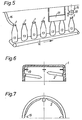
- Fig. 5 shows schematically how the screw caps 1 can be placed on a plurality of containers 13 in a filling line.
- the containers 13 run in a known manner on a conveyor belt 14 which is moved further in time with a screw cap placement head 15.
- the individual screw caps 1 are placed on the container 13 by a magazine 16.
- the container mouths are passed so close to a friction arm 17 that the latter comes into contact with the screw caps 1.
- the coefficient of friction of the friction arm 17 is selected such that when the container 13 is advanced, the screw caps 1 are slightly rotated clockwise until the rotary movement is interrupted by the engagement of the stop element (inner seal 3 or projections 9).
- the screw caps 1 are thus in the prepositioning position.
- the screw caps 1 slide along the friction arm 17 without any further rotary movement taking place.
- the pre-positioning is thus carried out in the simplest way and without the need for a complex arrangement.
- FIG. 6 and 7 show a screw cap 1, in which a plurality of tongues 19 are provided as stop elements, which protrude approximately horizontally into the cap opening.
- the screw cap 1 When the screw cap 1 is screwed onto a container mouth 4 with an external thread 5 (FIG. 1), the tongues 19 initially rest on the upper edge of the container mouth 4 and fix the screw cap 1 in the prepositioning position. By applying a vertical closing pressure, or by overcoming the elastic resistance of the tongue 19, the screw cap 1 can then be completely applied to the container mouth 4.
- stop element z. B. in the form of projections analogous to the projections 9 (FIG. 4) on the external thread of the container mouth 4 or to arrange corresponding tongues or other mechanical stop elements at the container mouth.
- this is readily known to the person skilled in the art and represents a kinematic interchange of the arrangement of one or more stop elements provided on the screw cap according to the invention.
- the arrangement of the stop elements on the screw cap is particularly advantageous because the method according to the invention can be implemented without changing the standardized container openings can.
Landscapes
- Engineering & Computer Science (AREA)
- Mechanical Engineering (AREA)
- Closures For Containers (AREA)
- Mechanical Pencils And Projecting And Retracting Systems Therefor, And Multi-System Writing Instruments (AREA)
- Food-Manufacturing Devices (AREA)
- Tubes (AREA)
- Ultra Sonic Daignosis Equipment (AREA)
- Medicines Containing Antibodies Or Antigens For Use As Internal Diagnostic Agents (AREA)
- Control Of Stepping Motors (AREA)
- Prostheses (AREA)
- Supplying Of Containers To The Packaging Station (AREA)
- Cartons (AREA)
Priority Applications (1)
| Application Number | Priority Date | Filing Date | Title |
|---|---|---|---|
| AT81810033T ATE10482T1 (de) | 1980-02-21 | 1981-02-06 | Schraubkappe und verfahren zum verschliessen einer behaeltermuendung. |
Applications Claiming Priority (2)
| Application Number | Priority Date | Filing Date | Title |
|---|---|---|---|
| DE3006481 | 1980-02-21 | ||
| DE19803006481 DE3006481A1 (de) | 1980-02-21 | 1980-02-21 | Verfahren zum verschliessen einer behaeltermuendung und schraubkappe zur durchfuehrung des verfahrens |
Publications (3)
| Publication Number | Publication Date |
|---|---|
| EP0034998A2 EP0034998A2 (de) | 1981-09-02 |
| EP0034998A3 EP0034998A3 (en) | 1982-03-17 |
| EP0034998B1 true EP0034998B1 (de) | 1984-11-28 |
Family
ID=6095182
Family Applications (1)
| Application Number | Title | Priority Date | Filing Date |
|---|---|---|---|
| EP81810033A Expired EP0034998B1 (de) | 1980-02-21 | 1981-02-06 | Schraubkappe und Verfahren zum Verschliessen einer Behältermündung |
Country Status (16)
| Country | Link |
|---|---|
| US (1) | US4412409A (cg-RX-API-DMAC7.html) |
| EP (1) | EP0034998B1 (cg-RX-API-DMAC7.html) |
| JP (1) | JPS56131159A (cg-RX-API-DMAC7.html) |
| AT (1) | ATE10482T1 (cg-RX-API-DMAC7.html) |
| AU (1) | AU538857B2 (cg-RX-API-DMAC7.html) |
| BR (1) | BR8100919A (cg-RX-API-DMAC7.html) |
| CA (1) | CA1158201A (cg-RX-API-DMAC7.html) |
| DE (2) | DE3006481A1 (cg-RX-API-DMAC7.html) |
| DK (1) | DK73481A (cg-RX-API-DMAC7.html) |
| ES (1) | ES265272Y (cg-RX-API-DMAC7.html) |
| FI (1) | FI810529A7 (cg-RX-API-DMAC7.html) |
| GR (1) | GR72744B (cg-RX-API-DMAC7.html) |
| IE (1) | IE50689B1 (cg-RX-API-DMAC7.html) |
| NO (1) | NO810520L (cg-RX-API-DMAC7.html) |
| NZ (1) | NZ196311A (cg-RX-API-DMAC7.html) |
| ZA (1) | ZA811134B (cg-RX-API-DMAC7.html) |
Families Citing this family (15)
| Publication number | Priority date | Publication date | Assignee | Title |
|---|---|---|---|---|
| FR2513614A1 (fr) * | 1981-09-25 | 1983-04-01 | Oreal | Procede et dispositif de bouchage de recipients, notamment de flacons |
| EP0083506A1 (en) * | 1982-01-04 | 1983-07-13 | Unilever Plc | Closure cap |
| DE3204201A1 (de) * | 1982-02-06 | 1983-08-11 | Heinrich Josef Winter Kunststoffverarbeitung Und Werkzeugbau Gmbh, 6452 Hainburg | Kunststoff-schraubkappe fuer flaschen |
| EP0208390A1 (en) * | 1985-04-19 | 1987-01-14 | Ecolab Inc. | Spray cap and bottle engagement |
| DE3527644A1 (de) * | 1985-08-01 | 1987-02-12 | Kolley Klaus F | Verschluss fuer flaschen mit einem kronenkorken und verfahren zu seiner herstellung |
| CH676226A5 (cg-RX-API-DMAC7.html) * | 1988-04-25 | 1990-12-28 | Alfatechnic Ag | |
| AU2501997A (en) * | 1996-05-09 | 1997-12-05 | Crown Cork Ag | Container cap and container mouth |
| US5884790A (en) * | 1997-10-30 | 1999-03-23 | Crown Cork & Seal Technologies Corporation | Closure cap with braking structure |
| AU768786B2 (en) * | 2000-04-05 | 2004-01-08 | Scholle Ipn Corporation | Twist cap |
| AUPQ669800A0 (en) * | 2000-04-05 | 2000-05-04 | Scholle Corporation | Twist cap |
| DE20211431U1 (de) | 2002-07-12 | 2003-02-06 | Wella Ag, 64295 Darmstadt | Verschluss für einen Behälter |
| US6968965B1 (en) * | 2003-10-03 | 2005-11-29 | Cunningham Kelly W | Container closure assembly |
| US7735664B1 (en) * | 2006-04-18 | 2010-06-15 | Portola Packaging, Inc. | Tapered thread structure |
| ITAR20090040A1 (it) * | 2009-11-04 | 2011-05-05 | Icm Macchine Divisione Della Silo S Pa | Pinza per calettare tappi |
| EP3153413B1 (en) * | 2015-10-05 | 2018-09-19 | Tetra Laval Holdings & Finance S.A. | A method of, and an applying apparatus comprising an applying head for, applying a lid onto a container |
Family Cites Families (16)
| Publication number | Priority date | Publication date | Assignee | Title |
|---|---|---|---|---|
| DE1083686B (de) * | 1953-11-23 | 1960-06-15 | Hunter Thomas Ltd | Verfahren und Vorrichtung zum Verschliessen von Gefaessen mit Steckgewinde-Blechdeckeln |
| FR1117259A (fr) * | 1954-12-21 | 1956-05-22 | Air Sec | Bouchon à jupe taraudée |
| US3223269A (en) * | 1964-12-21 | 1965-12-14 | Owens Illinois Glass Co | Snap-on closure |
| DE1532568C3 (de) * | 1966-04-22 | 1975-05-28 | Owens-Illinois, Inc., Toledo, Ohio (V.St.A.) | Vorrichtung zum Aufsetzen eines DrehverschluBdeckels auf einen Behälter |
| US3441161A (en) * | 1967-03-09 | 1969-04-29 | Paul S Van Baarn | Bottle cap |
| US3435976A (en) * | 1967-11-13 | 1969-04-01 | Afa Corp | Closure construction |
| US3592349A (en) * | 1969-05-22 | 1971-07-13 | Ethyl Dev Corp | Plastic container and closure |
| US3707240A (en) * | 1970-08-27 | 1972-12-26 | Polytop Corp | Closure with tear-off skirt |
| DE2106897A1 (de) * | 1971-02-13 | 1972-09-21 | Fa Robert Fmke, 5951 Lenhausen | Flasche mit Schraubkappenverschluß |
| US3822027A (en) * | 1973-01-08 | 1974-07-02 | S Cherba | Container with safety cap |
| FR2240160A1 (en) * | 1973-08-06 | 1975-03-07 | Joud Fernand | Plastic cap for container capping machine - has ramp upper surface for positioning by suction head |
| CA1038806A (en) * | 1974-11-05 | 1978-09-19 | Dietmar Aichinger | Closure for containers |
| DE2529340C3 (de) * | 1975-07-01 | 1980-08-28 | Albert Obrist Ag, Reinach, Basel (Schweiz) | Behälter mit einer Schraubkappe und Verfahren zum Aufsetzen der Schraubkappe |
| US4098419A (en) * | 1977-02-18 | 1978-07-04 | Maxcap Inc. | Blow molded plastic bottle and antitamper cap |
| FR2391117A2 (fr) * | 1977-05-20 | 1978-12-15 | Grussen Jean | Capsule de bouchage a vis a etancheite amelioree et moule de fabrication |
| US4248356A (en) * | 1978-01-09 | 1981-02-03 | Aci Technical Centre Pty. Ltd. | Sealing method |
-
1980
- 1980-02-21 DE DE19803006481 patent/DE3006481A1/de not_active Withdrawn
-
1981
- 1981-01-27 GR GR63978A patent/GR72744B/el unknown
- 1981-01-30 CA CA000369812A patent/CA1158201A/en not_active Expired
- 1981-02-06 DE DE8181810033T patent/DE3167362D1/de not_active Expired
- 1981-02-06 EP EP81810033A patent/EP0034998B1/de not_active Expired
- 1981-02-06 AT AT81810033T patent/ATE10482T1/de active
- 1981-02-13 US US06/234,558 patent/US4412409A/en not_active Expired - Fee Related
- 1981-02-16 AU AU67354/81A patent/AU538857B2/en not_active Ceased
- 1981-02-16 NO NO810520A patent/NO810520L/no unknown
- 1981-02-16 BR BR8100919A patent/BR8100919A/pt unknown
- 1981-02-19 DK DK73481A patent/DK73481A/da not_active Application Discontinuation
- 1981-02-20 FI FI810529A patent/FI810529A7/fi not_active Application Discontinuation
- 1981-02-20 ZA ZA00811134A patent/ZA811134B/xx unknown
- 1981-02-20 NZ NZ196311A patent/NZ196311A/xx unknown
- 1981-02-20 ES ES1981265272U patent/ES265272Y/es not_active Expired
- 1981-02-20 IE IE344/81A patent/IE50689B1/en unknown
- 1981-02-20 JP JP2418181A patent/JPS56131159A/ja active Pending
Also Published As
| Publication number | Publication date |
|---|---|
| DE3167362D1 (en) | 1985-01-10 |
| AU538857B2 (en) | 1984-08-30 |
| ES265272Y (es) | 1986-05-16 |
| AU6735481A (en) | 1981-08-27 |
| ZA811134B (en) | 1982-03-31 |
| NZ196311A (en) | 1983-12-16 |
| BR8100919A (pt) | 1981-08-25 |
| FI810529L (fi) | 1981-08-22 |
| DK73481A (da) | 1981-08-22 |
| GR72744B (cg-RX-API-DMAC7.html) | 1983-12-02 |
| DE3006481A1 (de) | 1981-08-27 |
| ES265272U (es) | 1985-04-16 |
| JPS56131159A (en) | 1981-10-14 |
| EP0034998A3 (en) | 1982-03-17 |
| US4412409A (en) | 1983-11-01 |
| IE810344L (en) | 1981-08-21 |
| CA1158201A (en) | 1983-12-06 |
| ATE10482T1 (de) | 1984-12-15 |
| FI810529A7 (fi) | 1981-08-22 |
| NO810520L (no) | 1981-08-24 |
| EP0034998A2 (de) | 1981-09-02 |
| IE50689B1 (en) | 1986-06-11 |
Similar Documents
| Publication | Publication Date | Title |
|---|---|---|
| EP0034998B1 (de) | Schraubkappe und Verfahren zum Verschliessen einer Behältermündung | |
| DE1946898A1 (de) | Behaelter mit einer Verschlusskappe | |
| DE2421292A1 (de) | Sicherheitsverschluss | |
| EP0111798A2 (de) | Selbsttätiger Verschluss für flexible Behälter | |
| DE2529340B2 (de) | Behälter mit einer Schraubkappe und Verfahren zum Aufsetzen der Schraubkappe | |
| CH607702A5 (en) | Bottle closure, in particular a screw closure, and process for fastening the closure | |
| DE4425675C3 (de) | Verschlußkappe | |
| EP0711538B1 (de) | Universalflaschenverschluss für enterale Überleitungsgeräte | |
| DE837966C (de) | Dichtung zu metallischen Verschlusskapseln fuer Flaschen und aehnliche Behaelter | |
| DE69303455T2 (de) | Temporäre Verschlussvorrichtung für eine Flasche | |
| DE3505426C1 (de) | Verschlußschraube aus Kunststoff für Spundbehälter | |
| EP0210322A1 (de) | Tankstutzen | |
| DE2530650C3 (de) | Drehverschluß zum Verschließen von unter Innendruck stehenden Behältern | |
| DE2913883A1 (de) | Behaeltnis, insbesondere flasche | |
| DE2641543A1 (de) | Schraubverschluss fuer behaelter | |
| DE4008010C2 (cg-RX-API-DMAC7.html) | ||
| EP0215202B1 (de) | Verfahren zur Herstellung einer Verschlusskappe aus Kunststoff für flaschenartige Behälter | |
| CH556274A (de) | Gefaess mit schraubkappe. | |
| DE3104525A1 (de) | Kugelauftragvorrichtung mit schraubkappe fuer eine flasche o.dgl. | |
| DE2833099A1 (de) | Verschlusstopfen aus elastischem kunststoff | |
| DE2200536A1 (de) | Einrichtung zur getrennten aufbewahrung zweier verschiedener stoffe | |
| DE1161776B (de) | Verschlusskappe fuer Flaschen mit einem Tropfeinsatz | |
| DE8708695U1 (de) | Flasche mit Kappe | |
| DE1482531C3 (de) | EntnahmeverschluBfür Behälter mit Gewindehals | |
| DE1089293B (de) | Verschluss fuer Behaelter, wie Flaschen u. dgl. |
Legal Events
| Date | Code | Title | Description |
|---|---|---|---|
| PUAI | Public reference made under article 153(3) epc to a published international application that has entered the european phase |
Free format text: ORIGINAL CODE: 0009012 |
|
| AK | Designated contracting states |
Designated state(s): AT BE CH DE FR GB IT NL SE |
|
| PUAL | Search report despatched |
Free format text: ORIGINAL CODE: 0009013 |
|
| AK | Designated contracting states |
Designated state(s): AT BE CH DE FR GB IT NL SE |
|
| 17P | Request for examination filed |
Effective date: 19820311 |
|
| GRAA | (expected) grant |
Free format text: ORIGINAL CODE: 0009210 |
|
| AK | Designated contracting states |
Designated state(s): AT BE CH DE FR GB IT LI NL SE |
|
| PG25 | Lapsed in a contracting state [announced via postgrant information from national office to epo] |
Ref country code: SE Effective date: 19841128 Ref country code: NL Effective date: 19841128 Ref country code: IT Free format text: LAPSE BECAUSE OF FAILURE TO SUBMIT A TRANSLATION OF THE DESCRIPTION OR TO PAY THE FEE WITHIN THE PRESCRIBED TIME-LIMIT;WARNING: LAPSES OF ITALIAN PATENTS WITH EFFECTIVE DATE BEFORE 2007 MAY HAVE OCCURRED AT ANY TIME BEFORE 2007. THE CORRECT EFFECTIVE DATE MAY BE DIFFERENT FROM THE ONE RECORDED. Effective date: 19841128 |
|
| REF | Corresponds to: |
Ref document number: 10482 Country of ref document: AT Date of ref document: 19841215 Kind code of ref document: T |
|
| REF | Corresponds to: |
Ref document number: 3167362 Country of ref document: DE Date of ref document: 19850110 |
|
| ET | Fr: translation filed | ||
| PG25 | Lapsed in a contracting state [announced via postgrant information from national office to epo] |
Ref country code: AT Effective date: 19850206 |
|
| NLV1 | Nl: lapsed or annulled due to failure to fulfill the requirements of art. 29p and 29m of the patents act | ||
| PLBE | No opposition filed within time limit |
Free format text: ORIGINAL CODE: 0009261 |
|
| STAA | Information on the status of an ep patent application or granted ep patent |
Free format text: STATUS: NO OPPOSITION FILED WITHIN TIME LIMIT |
|
| 26N | No opposition filed | ||
| BERE | Be: lapsed |
Owner name: ALBERT OBRIST A.G. Effective date: 19870228 |
|
| GBPC | Gb: european patent ceased through non-payment of renewal fee | ||
| PG25 | Lapsed in a contracting state [announced via postgrant information from national office to epo] |
Ref country code: FR Free format text: LAPSE BECAUSE OF NON-PAYMENT OF DUE FEES Effective date: 19871030 |
|
| REG | Reference to a national code |
Ref country code: FR Ref legal event code: ST |
|
| PG25 | Lapsed in a contracting state [announced via postgrant information from national office to epo] |
Ref country code: GB Effective date: 19881118 |
|
| PG25 | Lapsed in a contracting state [announced via postgrant information from national office to epo] |
Ref country code: BE Effective date: 19890228 |
|
| PGFP | Annual fee paid to national office [announced via postgrant information from national office to epo] |
Ref country code: DE Payment date: 19910214 Year of fee payment: 11 |
|
| PGFP | Annual fee paid to national office [announced via postgrant information from national office to epo] |
Ref country code: CH Payment date: 19910513 Year of fee payment: 11 |
|
| PG25 | Lapsed in a contracting state [announced via postgrant information from national office to epo] |
Ref country code: LI Effective date: 19920229 Ref country code: CH Effective date: 19920229 |
|
| REG | Reference to a national code |
Ref country code: CH Ref legal event code: PL |
|
| PG25 | Lapsed in a contracting state [announced via postgrant information from national office to epo] |
Ref country code: DE Effective date: 19921103 |