EP0033372A1 - Système de freinage pour moteurs à combustion interne à soupapes - Google Patents
Système de freinage pour moteurs à combustion interne à soupapes Download PDFInfo
- Publication number
- EP0033372A1 EP0033372A1 EP80107377A EP80107377A EP0033372A1 EP 0033372 A1 EP0033372 A1 EP 0033372A1 EP 80107377 A EP80107377 A EP 80107377A EP 80107377 A EP80107377 A EP 80107377A EP 0033372 A1 EP0033372 A1 EP 0033372A1
- Authority
- EP
- European Patent Office
- Prior art keywords
- control shaft
- cam
- camshaft
- braking device
- additional cam
- Prior art date
- Legal status (The legal status is an assumption and is not a legal conclusion. Google has not performed a legal analysis and makes no representation as to the accuracy of the status listed.)
- Granted
Links
Images


Classifications
-
- F—MECHANICAL ENGINEERING; LIGHTING; HEATING; WEAPONS; BLASTING
- F02—COMBUSTION ENGINES; HOT-GAS OR COMBUSTION-PRODUCT ENGINE PLANTS
- F02D—CONTROLLING COMBUSTION ENGINES
- F02D13/00—Controlling the engine output power by varying inlet or exhaust valve operating characteristics, e.g. timing
- F02D13/02—Controlling the engine output power by varying inlet or exhaust valve operating characteristics, e.g. timing during engine operation
- F02D13/04—Controlling the engine output power by varying inlet or exhaust valve operating characteristics, e.g. timing during engine operation using engine as brake
-
- F—MECHANICAL ENGINEERING; LIGHTING; HEATING; WEAPONS; BLASTING
- F01—MACHINES OR ENGINES IN GENERAL; ENGINE PLANTS IN GENERAL; STEAM ENGINES
- F01L—CYCLICALLY OPERATING VALVES FOR MACHINES OR ENGINES
- F01L1/00—Valve-gear or valve arrangements, e.g. lift-valve gear
- F01L1/02—Valve drive
- F01L1/04—Valve drive by means of cams, camshafts, cam discs, eccentrics or the like
- F01L1/08—Shape of cams
-
- F—MECHANICAL ENGINEERING; LIGHTING; HEATING; WEAPONS; BLASTING
- F01—MACHINES OR ENGINES IN GENERAL; ENGINE PLANTS IN GENERAL; STEAM ENGINES
- F01L—CYCLICALLY OPERATING VALVES FOR MACHINES OR ENGINES
- F01L13/00—Modifications of valve-gear to facilitate reversing, braking, starting, changing compression ratio, or other specific operations
- F01L13/06—Modifications of valve-gear to facilitate reversing, braking, starting, changing compression ratio, or other specific operations for braking
Definitions
- the invention relates to a braking device for a valve-controlled internal combustion engine for motor vehicles, in which each cylinder has at least one exhaust valve which can be controlled in the opening direction via a camshaft with a main cam for driving operation and with an additional cam which engages in braking operation.
- Vehicles with a permissible total weight of more than 9 t must have a third braking device, the so-called engine brake, which is designed as a permanent brake, in addition to the prescribed service brake and parking brake.
- engine brake which is designed as a permanent brake, in addition to the prescribed service brake and parking brake.
- Such an engine brake device is known from DE-OS 15 26 485.
- a device is described there, in which the camshaft has two cams for each exhaust valve, which are arranged one behind the other.
- the second cam works together with a hydraulic tappet, via which the corresponding exhaust valve can also be operated in braking mode.
- the second cam is arranged on the camshaft in such a way that it is at or near the end of the compression Hubes opens the starter valve so that compressed air is released from the cylinder and thus energy can escape, which would otherwise move the piston downward during its subsequent expansion stroke. This ensures that the internal combustion engine must be driven even in the phase of the expansion stroke, since the piston moved downward is not moved by the compressed air, but is driven by the moving vehicle via the crankshaft.
- the object of the present invention is therefore to propose a device for an engine brake device for reciprocating piston internal combustion engines of the type mentioned at the outset which do not have these disadvantages.
- the additional cam is arranged retractable in the plane of the main cam and in the camshaft. This makes it possible to integrate the additional cam, which is only required in braking operation, in the main cam, so that the camshaft has the same overall length as without additional cams despite additional cams. Another advantage can be seen in the fact that the additional cam acts on the same rocker arm without the interposition of further transmission elements as the main cam.
- the additional cam is designed in such a way that it closes when top dead center is reached, the advantage is achieved that a supply of the cylinder back pressure from the exhaust system is avoided and even through the subsequent expansion that occurs in top dead center Residual air remaining in the cylinder generates a negative pressure, which also represents a further additional braking effect. Due to these opening and closing conditions, the highest possible braking performance is achieved without damage to the internal combustion engine as a result of difficulties in lubricating the cylinder.
- a further development of the invention proposes to actuate the additional cam, which may only intervene in the valve train when the internal combustion engine is braking, via a control shaft arranged in the axis of rotation of the camshaft.
- This embodiment has the advantage that no additional space is required for a separate control device for actuating the additional cam on each additional cam itself. Due to the control shaft in the camshaft, it is possible to have all the auxiliary cams of the internal combustion engine extended or retracted simultaneously.
- control shaft is arranged axially displaceably in the camshaft and has a shoulder with conical flanks in the region of the additional cam.
- the actuation of the control shaft becomes particularly simple when it only has to be actuated in one direction and is brought back into its starting position in the other direction by the force of a spring. It is useful that the control shaft from a tax device is operated only in braking mode and that the spring holds the control shaft in its unactuated position.
- the control shaft can be moved electrically, pneumatically, hydraulically or by means of a linkage by hand or in connection with the activation of the brake operation control.
- This simply constructed transmission takes up little space and can be operated by means of actuating devices arranged on the outside of the cylinder head, with the camshaft at the top. Particular emphasis was placed on the fact that large forces that are required to hold the additional cam in its extended position can also be transmitted.
- a cylindrical roller which is fitted in an opening in the camshaft and which is prevented from completely emerging from the camshaft by a tapering of the opening diameter towards the outer circumference of the main cam, is suitable as an additional cam.
- This type of additional cam allows in connection with a slidably mounted control shaft a simple embodiment, which has the necessary surface pressure for actuating the exhaust valve. Obtaining the additional cam is particularly easy, since the additional cam is pressed back into its bore by the closing pressure of the valve when the control shaft is in the rest position.
- Another development of the invention provides that instead of the angle lever for displacing the control shaft, its free end is designed as a piston which is actuated via pressure oil against the force of the rest spring.
- This embodiment which means a slight extension of the overall length, since a cylinder space must be protruded at the end of the control shaft, has the advantage that in this way lubrication of the movably mounted control shaft and - if desired - the additional cam can take place, since this can be shifted required pressure oil from the control shaft can be easily removed from the oil sump of the internal combustion engine.
- This has the further advantage that only a controllable valve has to be arranged in this pressure line, which valve is actuated accordingly during braking operation.
- control shaft to be arranged in the camshaft in a circumferential manner and for an eccentric to be provided in the region of the additional cams.
- additional cam becomes relative to the cam by rotating the eccentric wave actuated.
- the rotation is expedient against the force of a spring which is arranged between the camshaft and the control shaft and holds the latter in the rest position.
- control shaft can be rotated in such a way that the additional cam engages in the valve train when a front face of the control shaft protrudes from the camshaft and a hydraulically operating clutch on this front face is provided, which is actuated in braking mode and rotates the control shaft counter to the camshaft direction of rotation.
- An additional cam which advantageously cooperates with a rotatably arranged control shaft is characterized in that it is essentially cylindrical and is rotatably attached to the control shaft.
- This additional cam it is advantageous if it widens like a cup in the direction of displacement. It is easily possible to optimize the guiding surface for your management task without great manufacturing expenditure.
- This type of additional cam allows a clear assignment of its position to the position of the control shaft and thus to the operating state of the hydraulic clutch rotating the control shaft.
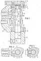
- FIG. 1 shows a longitudinal section through a hollow-drilled camshaft 1, which is mounted in slide bearings 2 in the housing 3 or cylinder head of an internal combustion engine (not shown further here). It is driven by a gear 4, which is attached to one of its end faces.
- a gear 4 which is attached to one of its end faces.
- any other type of drive is also possible.
- a control shaft 6 is mounted in the axis of rotation 5 of the camshaft 1, which rotates - but not necessarily - with the camshaft 1 and is arranged axially displaceably in the camshaft 1 against the force of a spring 7.
- the spring 7 is supported on the one hand on the drive gear 4 and on the other hand on an end face of the control shaft 6.
- the spring 7 has the task of holding the control shaft 6 in its initial position or rest position. This corresponds to the "driving mode" position.
- the other end face of the control shaft 6 is designed as a piston 8, which is guided in a housing 9 acting as a cylinder.
- a bore 10 to the pressure chamber 17 is provided in the housing 9, to which a pressure medium line can be connected.
- the camshaft 1 shown in FIG. 1 also has two cams 11, 12, of which the cam 11 controls an exhaust valve, not shown here, and the cam 12 controls an intake valve, also not shown, of the internal combustion engine. Only parts of the pushrods of the valve control are shown. Approximately 160 ° in the direction of rotation of the camshaft in front of the cam tip of the cam 11, the cam has an opening 13 in which a roller working as an additional cam 14 is arranged so as to be retractable (FIGS. 1, 3). The additional cam 14 is extended by the control shaft 6.
- the control shaft 6 in the region of the cam 11 has a circumferential collar 15 which projects out of the control shaft via conical transitions 16.
- Fig. 1 the control shaft 6 is shown in the braking mode position.
- the circumferential collar 15 is located under the additional cam 14 so that it has moved out of the cam base circle and can actuate the exhaust valve.
- a pressure medium advantageously engine oil
- the pressure medium supplied under pressure acts in the pressure chamber 17 on the piston 8, so that the control shaft 6 is axially displaced against the force of the spring 7.
- the pressure medium supply to the supply bore 10 is interrupted and the pressure chamber 17 is depressurized.
- the spring 7 can shift the control shaft 6.
- the piston 8 empties the pressure chamber 17.
- the axial displacement of the control shaft 6 by the spring 7 causes the sections of the control shaft with thinner diameters to come to rest under the additional cam 14 (FIG. 3).
- the first rotation of the camshaft following the backward displacement of the control shaft causes the tappet of the exhaust valve to push the additional cam 14 still pushed out into its opening 13 due to the closing force of the exhaust valve.
- the exhaust valve can only be operated by the cam 11 alone.
- FIGS. 4a, b show an alternative embodiment of the actuation of the control shaft 6.
- the free end of the control shaft 6 does not have a piston 8, but a recess 20.
- a link piece 21 engages in this recess, which can be pivoted via a gear mechanism formed by a lever 22 and a shaft 23.
- the pivoting movement of the shaft 23 causes the link piece to axially shift the control shaft 6.
- This displacement arrangement is also housed in a separate housing 9.1, which is flanged to the housing 3 of the internal combustion engine.
- the pivoting movement of the shaft 23 can be carried out manually, hydraulically or electrically.
- control shaft 6 rotates with the camshaft 1 and is still relatively rotatable with respect to the latter. It has a hydraulically operating clutch 30 on its free end face instead of a piston.
- the clutch 30 consists of a clutch half 30.1 firmly connected to the control shaft and of a clutch half 30.2 arranged in the housing 3 so as to be screwable.
- the clutch is supplied with oil from the internal combustion engine via a supply line 31.
- a gap is provided between the two coupling halves, which serves for the oil flow so that the coupling empties automatically when the oil supply is switched off.
- control shaft 6 in FIG. 5 has an eccentric 32 at the level of the additional cam 14.1.
- the additional cam 14.1 is rotatably attached to the eccentric 32 by moving its cheeks over the center of the eccentric base circle to grab.
- the additional cam 14.1 has a cup-shaped outer contour in Fig. 5.
- the cup-shaped edge 40 also serves as a guide for the additional cam in the opening 13. This also ensures that the additional cam 14.1 can move back and forth with the control shaft 6 due to its eccentric attachment in the opening 13 due to its eccentric attachment.
- the hydraulically operating clutch 30 is filled by the supply line 31.
- the filling creates a frictional connection between the coupling half 30.1 rotating with the camshaft and the standing half 30.2.
- the control shaft 6 is rotated against the force of the spring 33 and 180 ° to a further stop 38 (FIG. 7).
- Both stops 35 and 37 are connected to one another via a semicircular annular groove 39 in which the nose 37 is guided.
- the eccentric 32 pushes the additional cam 14.1 out of the opening 13 by the amount of its eccentricity.
- the additional cam 14.1 thus comes into operative connection with the outlet valve, so that it is additionally opened.
- the hydraulically operating clutch 30 is no longer filled with oil through the supply line 31.
- the oil can now flow out of the hydraulically operating clutch 30 through gaps between the two clutch halves 30.1 and 30.2 and thus returns to the oil sump of the internal combustion engine via corresponding channels 34.
- the torsion spring 33 can turn the control shaft 6 back so that the additional cam 14.1 is retracted.
- the cam 11 again takes over the control of the exhaust valve in the usual way.
Applications Claiming Priority (2)
| Application Number | Priority Date | Filing Date | Title |
|---|---|---|---|
| DE3003566 | 1980-02-01 | ||
| DE19803003566 DE3003566A1 (de) | 1980-02-01 | 1980-02-01 | Bremsvorrichtung fuer eine ventilgesteuerte brennkraftmaschine |
Publications (2)
| Publication Number | Publication Date |
|---|---|
| EP0033372A1 true EP0033372A1 (fr) | 1981-08-12 |
| EP0033372B1 EP0033372B1 (fr) | 1983-12-21 |
Family
ID=6093428
Family Applications (1)
| Application Number | Title | Priority Date | Filing Date |
|---|---|---|---|
| EP80107377A Expired EP0033372B1 (fr) | 1980-02-01 | 1980-11-26 | Système de freinage pour moteurs à combustion interne à soupapes |
Country Status (3)
| Country | Link |
|---|---|
| US (2) | US4378765A (fr) |
| EP (1) | EP0033372B1 (fr) |
| DE (1) | DE3003566A1 (fr) |
Cited By (1)
| Publication number | Priority date | Publication date | Assignee | Title |
|---|---|---|---|---|
| DE3920528C1 (en) * | 1989-06-22 | 1990-06-07 | Daimler-Benz Aktiengesellschaft, 7000 Stuttgart, De | IC engine camshaft drive - incorporates braking system controlled by microprocessor to eliminate drive chain chatter |
Families Citing this family (25)
| Publication number | Priority date | Publication date | Assignee | Title |
|---|---|---|---|---|
| US4455977A (en) * | 1981-08-31 | 1984-06-26 | Tecumseh Products Company | Compression brake system |
| US4587936A (en) * | 1981-09-10 | 1986-05-13 | Honda Giken Kogyo Kabushiki Kaisha | Control apparatus for intake and exhaust valves of an internal combustion engine |
| USRE33499E (en) * | 1983-06-29 | 1990-12-18 | Honda Giken Kogyo Kabushiki Kaisha | Method and apparatus for the control of valve operations in internal combustion engine |
| JPS608407A (ja) * | 1983-06-29 | 1985-01-17 | Honda Motor Co Ltd | 内燃機関の弁作動制御装置 |
| US4696266A (en) * | 1985-05-14 | 1987-09-29 | Fuji Jukogyo Kabushiki Kaisha | Decompression apparatus for engines |
| JPH01500920A (ja) * | 1986-05-21 | 1989-03-30 | ベネット、オートモーティブ、テクノロジー、プロプライエタリ、リミテッド | 気体燃料を使用するエンジンの改良 |
| DE3900739A1 (de) * | 1989-01-12 | 1990-07-19 | Man Nutzfahrzeuge Ag | Verfahren zur steigerung der motorbremsleistung bei viertakt-hubkolben-brennkraftmaschinen |
| SE466320B (sv) * | 1989-02-15 | 1992-01-27 | Volvo Ab | Foerfarande och anordning foer motorbromsning med en fyrtakts foerbraenningsmotor |
| IT1255447B (it) * | 1991-11-08 | 1995-10-31 | Iveco Fiat | Motore provvisto di un dispositivo di frenatura continua, particolarmente per un veicolo industriale. |
| US5402759A (en) * | 1994-07-08 | 1995-04-04 | Outboard Marine Corporation | Cylinder decompression arrangement in cam shaft |
| US5540201A (en) * | 1994-07-29 | 1996-07-30 | Caterpillar Inc. | Engine compression braking apparatus and method |
| US5647318A (en) * | 1994-07-29 | 1997-07-15 | Caterpillar Inc. | Engine compression braking apparatus and method |
| US5526784A (en) * | 1994-08-04 | 1996-06-18 | Caterpillar Inc. | Simultaneous exhaust valve opening braking system |
| US5787859A (en) * | 1997-02-03 | 1998-08-04 | Diesel Engine Retarders, Inc. | Method and apparatus to accomplish exhaust air recirculation during engine braking and/or exhaust gas recirculation during positive power operation of an internal combustion engine |
| US5809964A (en) * | 1997-02-03 | 1998-09-22 | Diesel Engine Retarders, Inc. | Method and apparatus to accomplish exhaust air recirculation during engine braking and/or exhaust gas recirculation during positive power operation of an internal combustion engine |
| US5957097A (en) * | 1997-08-13 | 1999-09-28 | Harley-Davidson Motor Company | Internal combustion engine with automatic compression release |
| JP4020346B2 (ja) * | 1998-10-12 | 2007-12-12 | ヤマハ発動機株式会社 | エンジンのデコンプ機構 |
| US6189497B1 (en) | 1999-04-13 | 2001-02-20 | Gary L. Griffiths | Variable valve lift and timing camshaft support mechanism for internal combustion engines |
| DE10038916B4 (de) * | 2000-08-09 | 2004-02-19 | Fev Motorentechnik Gmbh | Kolbenbrennkraftmaschine mit Gaswechselventilen, die zur Erzeugung einer zusätzlichen Bremsleistung steuerbar sind |
| AT500680B8 (de) * | 2004-07-01 | 2007-02-15 | Avl List Gmbh | Vorrichtung zum zuschalten einer zusätzlichen nockenerhebung für eine brennkraftmaschine |
| DE102005023006B4 (de) * | 2005-05-19 | 2019-05-23 | Daimler Ag | Nockenwellenverstelleinrichtung |
| DE102007056749A1 (de) * | 2007-11-26 | 2009-05-28 | Knorr-Bremse Systeme für Nutzfahrzeuge GmbH | Ventiltrieb einer Brennkraftmaschine mit Mitteln zur Motorbremsung |
| DE102010011455A1 (de) | 2010-03-15 | 2011-09-15 | Schaeffler Technologies Gmbh & Co. Kg | Hubkolbenbrennkraftmaschine mit einstellbarem Aufpumpelement |
| DE102010011454B4 (de) | 2010-03-15 | 2020-08-06 | Schaeffler Technologies AG & Co. KG | Hubkolbenbrennkraftmaschine mit Dekompressionsmotorbremse |
| DE102011005575A1 (de) | 2011-03-15 | 2012-09-20 | Schaeffler Technologies Gmbh & Co. Kg | Ventiltrieb mit Zusatzhub im Nockengrundkreis |
Citations (1)
| Publication number | Priority date | Publication date | Assignee | Title |
|---|---|---|---|---|
| FR55635E (fr) * | 1943-02-08 | 1952-09-02 | Groupement Francais Pour Le Developpement Des Recherches Aeronautiques | Moteur à deux temps à injection de combustible volatil |
Family Cites Families (17)
| Publication number | Priority date | Publication date | Assignee | Title |
|---|---|---|---|---|
| FR334619A (fr) * | 1903-08-13 | 1903-12-28 | Gustave Cornilleau | Came extensible pour la régulation des moteurs |
| US862448A (en) * | 1906-04-20 | 1907-08-06 | Gustave Cornilleau | Explosive-engine. |
| US868765A (en) * | 1906-11-19 | 1907-10-22 | Dock Gas Engine Company | Internal-combustion engine. |
| AT33177B (de) * | 1907-05-15 | 1908-06-10 | Anciens Etablissements Panhard | Verfahren und Einrichtung zum Bremsen von Kraftwagen mittels der Antriebskraftmaschine. |
| US1080495A (en) * | 1912-03-13 | 1913-12-02 | Gen Electric | Valve-gear for internal-combustion engines. |
| US1439798A (en) * | 1921-07-09 | 1922-12-26 | Wright Aeronautical Corp | Compression-relief device for internal-combustion engines |
| GB268984A (en) * | 1926-05-13 | 1927-04-14 | Triumph Cycle Co Ltd | Improvements in the construction of cams for valve operating mechanism |
| GB371519A (en) * | 1931-02-18 | 1932-04-28 | Ici Ltd | Compression release device for internal-combustion engines |
| US2178152A (en) * | 1938-03-14 | 1939-10-31 | Clinton L Walker | Brake cycle for internal combustion engines |
| DE950037C (de) * | 1953-11-12 | 1956-10-04 | Eisen & Stahlind Ag | Vorrichtung fuer Viertakt-Motoren mit von der Kurbelwelle angetriebener Steuerwelle zur Ermoeglichung eines wahlweisen Betriebs des Motors als Verdichter |
| US3144009A (en) * | 1962-05-14 | 1964-08-11 | Dick Schoep | Variable valve timing mechanism |
| BE673717A (fr) * | 1965-01-12 | 1966-06-14 | ||
| US3332405A (en) * | 1965-10-01 | 1967-07-25 | Jacobs Mfg Co | Internal combustion engine brake |
| US3395689A (en) * | 1966-09-15 | 1968-08-06 | Studebaker Corp | Engine decompression apparatus |
| US3523465A (en) * | 1968-10-31 | 1970-08-11 | William Emory Harrell | Adjustable cam shafts |
| FR2258561B1 (fr) * | 1974-01-21 | 1976-10-08 | Renault | |
| FR2298000A1 (fr) * | 1975-01-17 | 1976-08-13 | Bernard Moteurs | Dispositif de decompression pour faciliter le lancement de moteurs a combustion interne |
-
1980
- 1980-02-01 DE DE19803003566 patent/DE3003566A1/de not_active Withdrawn
- 1980-11-26 EP EP80107377A patent/EP0033372B1/fr not_active Expired
-
1981
- 1981-01-28 US US06/229,124 patent/US4378765A/en not_active Expired - Fee Related
-
1983
- 1983-01-14 US US06/458,141 patent/US4440126A/en not_active Expired - Fee Related
Patent Citations (1)
| Publication number | Priority date | Publication date | Assignee | Title |
|---|---|---|---|---|
| FR55635E (fr) * | 1943-02-08 | 1952-09-02 | Groupement Francais Pour Le Developpement Des Recherches Aeronautiques | Moteur à deux temps à injection de combustible volatil |
Cited By (1)
| Publication number | Priority date | Publication date | Assignee | Title |
|---|---|---|---|---|
| DE3920528C1 (en) * | 1989-06-22 | 1990-06-07 | Daimler-Benz Aktiengesellschaft, 7000 Stuttgart, De | IC engine camshaft drive - incorporates braking system controlled by microprocessor to eliminate drive chain chatter |
Also Published As
| Publication number | Publication date |
|---|---|
| DE3003566A1 (de) | 1981-08-06 |
| US4440126A (en) | 1984-04-03 |
| US4378765A (en) | 1983-04-05 |
| EP0033372B1 (fr) | 1983-12-21 |
Similar Documents
| Publication | Publication Date | Title |
|---|---|---|
| EP0033372A1 (fr) | Système de freinage pour moteurs à combustion interne à soupapes | |
| EP0423160B1 (fr) | Dispositif d'entrainement de l'arbre a cames d'un moteur a combustion interne | |
| DE19703948C1 (de) | Vorrichtung zur Veränderung der Verdichtung einer Hubkolbenbrennkraftmaschine | |
| EP2132418B1 (fr) | Mécanisme de distribution pour des soupapes d'échange des gaz d'un moteur à combustion interne, doté d'un porte-came mobile et d'un engrenage à deux vis | |
| DE10230108B4 (de) | Vorrichtung zum Verstellen des Hubs eines von einer Nockenwelle betätigten Ventils | |
| EP0335083B1 (fr) | Dispositif de déplacement angulaire relatif entre deux arbres en liaison d'entraînement | |
| EP0469332A1 (fr) | Procédé pour changer le calage des soupapes d'un moteur à combustion interne | |
| DE4004726C2 (de) | Antriebseinheit eines Rollapparates einer Papiermaschine | |
| DE2542312B2 (de) | Vorrichtung zum pneumatischen Bremsen und Wiederanlassen in Gegendrehrichtung für einen Dieselmotor | |
| DE3815233A1 (de) | Antrieb fuer eine schmiermittelpumpe | |
| DE4410381A1 (de) | Ventiltrieb für eine Brennkraftmaschine | |
| EP0593908B1 (fr) | Frein moteur avec freinage des gaz d'échappement | |
| DE19600536C2 (de) | Vorrichtung zur variablen Steuerung eines Einlaßventils | |
| DE3937628A1 (de) | Antriebsvorrichtung fuer eine im zylinderkopf einer brennkraftmaschine gelagerten nockenwelle | |
| DE19702389A1 (de) | Ventiltrieb für eine Brennkraftmaschine | |
| DE2339529A1 (de) | Kraftstoffeinspritzpumpenverstellvorrichtung | |
| EP0020791A1 (fr) | Dispositif de commande d'une valve disposée dans la conduite d'air de charge d'un moteur à combustion | |
| DE19505725C2 (de) | Motorbremse | |
| DE2161518A1 (de) | Dampfmotor, insbesondere fur Kraft fahrzeuge | |
| DE10137072A1 (de) | Vorrichtung zum Antrieb von wenigstens einem Ventil eines Hubkolbenmotors | |
| DE3209813A1 (de) | Steuervorrichtung fuer eine kraftstoff-einspritzpumpe | |
| DE759760C (de) | Umsteuerbare Brennkraftmaschine | |
| DE869768C (de) | Durch ein Druckmittel gesteuerter Antrieb fuer eine wechselnde Dreh- oder Kippbewegung, insbesondere fuer Muelleimerkippvorrichtungen von Muellkraftwagen | |
| EP1505468B1 (fr) | Dispositif de commande | |
| DE4239040A1 (de) | Mechanisch-hydraulische Bewegungsübertragungsmittel zwischen Nockenwelle und Gaswechselventil einer Brennkraftmaschine |
Legal Events
| Date | Code | Title | Description |
|---|---|---|---|
| PUAI | Public reference made under article 153(3) epc to a published international application that has entered the european phase |
Free format text: ORIGINAL CODE: 0009012 |
|
| AK | Designated contracting states |
Designated state(s): CH FR GB NL SE |
|
| 17P | Request for examination filed |
Effective date: 19811024 |
|
| GRAA | (expected) grant |
Free format text: ORIGINAL CODE: 0009210 |
|
| AK | Designated contracting states |
Designated state(s): CH FR GB LI NL SE |
|
| ET | Fr: translation filed | ||
| PGFP | Annual fee paid to national office [announced via postgrant information from national office to epo] |
Ref country code: FR Payment date: 19841008 Year of fee payment: 5 |
|
| PGFP | Annual fee paid to national office [announced via postgrant information from national office to epo] |
Ref country code: CH Payment date: 19841015 Year of fee payment: 5 |
|
| PLBE | No opposition filed within time limit |
Free format text: ORIGINAL CODE: 0009261 |
|
| STAA | Information on the status of an ep patent application or granted ep patent |
Free format text: STATUS: NO OPPOSITION FILED WITHIN TIME LIMIT |
|
| 26N | No opposition filed | ||
| PGFP | Annual fee paid to national office [announced via postgrant information from national office to epo] |
Ref country code: SE Payment date: 19841231 Year of fee payment: 5 |
|
| PGFP | Annual fee paid to national office [announced via postgrant information from national office to epo] |
Ref country code: NL Payment date: 19851130 Year of fee payment: 6 |
|
| PG25 | Lapsed in a contracting state [announced via postgrant information from national office to epo] |
Ref country code: SE Effective date: 19861127 |
|
| PG25 | Lapsed in a contracting state [announced via postgrant information from national office to epo] |
Ref country code: LI Effective date: 19861130 Ref country code: CH Effective date: 19861130 |
|
| PG25 | Lapsed in a contracting state [announced via postgrant information from national office to epo] |
Ref country code: NL Effective date: 19870601 |
|
| NLV4 | Nl: lapsed or anulled due to non-payment of the annual fee | ||
| GBPC | Gb: european patent ceased through non-payment of renewal fee | ||
| PG25 | Lapsed in a contracting state [announced via postgrant information from national office to epo] |
Ref country code: FR Free format text: LAPSE BECAUSE OF NON-PAYMENT OF DUE FEES Effective date: 19870731 |
|
| REG | Reference to a national code |
Ref country code: CH Ref legal event code: PL |
|
| REG | Reference to a national code |
Ref country code: FR Ref legal event code: ST |
|
| PG25 | Lapsed in a contracting state [announced via postgrant information from national office to epo] |
Ref country code: GB Effective date: 19881118 |
|
| EUG | Se: european patent has lapsed |
Ref document number: 80107377.6 Effective date: 19870901 |