EP0033372A1 - Braking gear for valve controlled internal combustion engines - Google Patents
Braking gear for valve controlled internal combustion engines Download PDFInfo
- Publication number
- EP0033372A1 EP0033372A1 EP80107377A EP80107377A EP0033372A1 EP 0033372 A1 EP0033372 A1 EP 0033372A1 EP 80107377 A EP80107377 A EP 80107377A EP 80107377 A EP80107377 A EP 80107377A EP 0033372 A1 EP0033372 A1 EP 0033372A1
- Authority
- EP
- European Patent Office
- Prior art keywords
- control shaft
- cam
- camshaft
- braking device
- additional cam
- Prior art date
- Legal status (The legal status is an assumption and is not a legal conclusion. Google has not performed a legal analysis and makes no representation as to the accuracy of the status listed.)
- Granted
Links
Images


Classifications
-
- F—MECHANICAL ENGINEERING; LIGHTING; HEATING; WEAPONS; BLASTING
- F02—COMBUSTION ENGINES; HOT-GAS OR COMBUSTION-PRODUCT ENGINE PLANTS
- F02D—CONTROLLING COMBUSTION ENGINES
- F02D13/00—Controlling the engine output power by varying inlet or exhaust valve operating characteristics, e.g. timing
- F02D13/02—Controlling the engine output power by varying inlet or exhaust valve operating characteristics, e.g. timing during engine operation
- F02D13/04—Controlling the engine output power by varying inlet or exhaust valve operating characteristics, e.g. timing during engine operation using engine as brake
-
- F—MECHANICAL ENGINEERING; LIGHTING; HEATING; WEAPONS; BLASTING
- F01—MACHINES OR ENGINES IN GENERAL; ENGINE PLANTS IN GENERAL; STEAM ENGINES
- F01L—CYCLICALLY OPERATING VALVES FOR MACHINES OR ENGINES
- F01L1/00—Valve-gear or valve arrangements, e.g. lift-valve gear
- F01L1/02—Valve drive
- F01L1/04—Valve drive by means of cams, camshafts, cam discs, eccentrics or the like
- F01L1/08—Shape of cams
-
- F—MECHANICAL ENGINEERING; LIGHTING; HEATING; WEAPONS; BLASTING
- F01—MACHINES OR ENGINES IN GENERAL; ENGINE PLANTS IN GENERAL; STEAM ENGINES
- F01L—CYCLICALLY OPERATING VALVES FOR MACHINES OR ENGINES
- F01L13/00—Modifications of valve-gear to facilitate reversing, braking, starting, changing compression ratio, or other specific operations
- F01L13/06—Modifications of valve-gear to facilitate reversing, braking, starting, changing compression ratio, or other specific operations for braking
Definitions
- the invention relates to a braking device for a valve-controlled internal combustion engine for motor vehicles, in which each cylinder has at least one exhaust valve which can be controlled in the opening direction via a camshaft with a main cam for driving operation and with an additional cam which engages in braking operation.
- Vehicles with a permissible total weight of more than 9 t must have a third braking device, the so-called engine brake, which is designed as a permanent brake, in addition to the prescribed service brake and parking brake.
- engine brake which is designed as a permanent brake, in addition to the prescribed service brake and parking brake.
- Such an engine brake device is known from DE-OS 15 26 485.
- a device is described there, in which the camshaft has two cams for each exhaust valve, which are arranged one behind the other.
- the second cam works together with a hydraulic tappet, via which the corresponding exhaust valve can also be operated in braking mode.
- the second cam is arranged on the camshaft in such a way that it is at or near the end of the compression Hubes opens the starter valve so that compressed air is released from the cylinder and thus energy can escape, which would otherwise move the piston downward during its subsequent expansion stroke. This ensures that the internal combustion engine must be driven even in the phase of the expansion stroke, since the piston moved downward is not moved by the compressed air, but is driven by the moving vehicle via the crankshaft.
- the object of the present invention is therefore to propose a device for an engine brake device for reciprocating piston internal combustion engines of the type mentioned at the outset which do not have these disadvantages.
- the additional cam is arranged retractable in the plane of the main cam and in the camshaft. This makes it possible to integrate the additional cam, which is only required in braking operation, in the main cam, so that the camshaft has the same overall length as without additional cams despite additional cams. Another advantage can be seen in the fact that the additional cam acts on the same rocker arm without the interposition of further transmission elements as the main cam.
- the additional cam is designed in such a way that it closes when top dead center is reached, the advantage is achieved that a supply of the cylinder back pressure from the exhaust system is avoided and even through the subsequent expansion that occurs in top dead center Residual air remaining in the cylinder generates a negative pressure, which also represents a further additional braking effect. Due to these opening and closing conditions, the highest possible braking performance is achieved without damage to the internal combustion engine as a result of difficulties in lubricating the cylinder.
- a further development of the invention proposes to actuate the additional cam, which may only intervene in the valve train when the internal combustion engine is braking, via a control shaft arranged in the axis of rotation of the camshaft.
- This embodiment has the advantage that no additional space is required for a separate control device for actuating the additional cam on each additional cam itself. Due to the control shaft in the camshaft, it is possible to have all the auxiliary cams of the internal combustion engine extended or retracted simultaneously.
- control shaft is arranged axially displaceably in the camshaft and has a shoulder with conical flanks in the region of the additional cam.
- the actuation of the control shaft becomes particularly simple when it only has to be actuated in one direction and is brought back into its starting position in the other direction by the force of a spring. It is useful that the control shaft from a tax device is operated only in braking mode and that the spring holds the control shaft in its unactuated position.
- the control shaft can be moved electrically, pneumatically, hydraulically or by means of a linkage by hand or in connection with the activation of the brake operation control.
- This simply constructed transmission takes up little space and can be operated by means of actuating devices arranged on the outside of the cylinder head, with the camshaft at the top. Particular emphasis was placed on the fact that large forces that are required to hold the additional cam in its extended position can also be transmitted.
- a cylindrical roller which is fitted in an opening in the camshaft and which is prevented from completely emerging from the camshaft by a tapering of the opening diameter towards the outer circumference of the main cam, is suitable as an additional cam.
- This type of additional cam allows in connection with a slidably mounted control shaft a simple embodiment, which has the necessary surface pressure for actuating the exhaust valve. Obtaining the additional cam is particularly easy, since the additional cam is pressed back into its bore by the closing pressure of the valve when the control shaft is in the rest position.
- Another development of the invention provides that instead of the angle lever for displacing the control shaft, its free end is designed as a piston which is actuated via pressure oil against the force of the rest spring.
- This embodiment which means a slight extension of the overall length, since a cylinder space must be protruded at the end of the control shaft, has the advantage that in this way lubrication of the movably mounted control shaft and - if desired - the additional cam can take place, since this can be shifted required pressure oil from the control shaft can be easily removed from the oil sump of the internal combustion engine.
- This has the further advantage that only a controllable valve has to be arranged in this pressure line, which valve is actuated accordingly during braking operation.
- control shaft to be arranged in the camshaft in a circumferential manner and for an eccentric to be provided in the region of the additional cams.
- additional cam becomes relative to the cam by rotating the eccentric wave actuated.
- the rotation is expedient against the force of a spring which is arranged between the camshaft and the control shaft and holds the latter in the rest position.
- control shaft can be rotated in such a way that the additional cam engages in the valve train when a front face of the control shaft protrudes from the camshaft and a hydraulically operating clutch on this front face is provided, which is actuated in braking mode and rotates the control shaft counter to the camshaft direction of rotation.
- An additional cam which advantageously cooperates with a rotatably arranged control shaft is characterized in that it is essentially cylindrical and is rotatably attached to the control shaft.
- This additional cam it is advantageous if it widens like a cup in the direction of displacement. It is easily possible to optimize the guiding surface for your management task without great manufacturing expenditure.
- This type of additional cam allows a clear assignment of its position to the position of the control shaft and thus to the operating state of the hydraulic clutch rotating the control shaft.
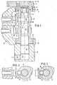
- FIG. 1 shows a longitudinal section through a hollow-drilled camshaft 1, which is mounted in slide bearings 2 in the housing 3 or cylinder head of an internal combustion engine (not shown further here). It is driven by a gear 4, which is attached to one of its end faces.
- a gear 4 which is attached to one of its end faces.
- any other type of drive is also possible.
- a control shaft 6 is mounted in the axis of rotation 5 of the camshaft 1, which rotates - but not necessarily - with the camshaft 1 and is arranged axially displaceably in the camshaft 1 against the force of a spring 7.
- the spring 7 is supported on the one hand on the drive gear 4 and on the other hand on an end face of the control shaft 6.
- the spring 7 has the task of holding the control shaft 6 in its initial position or rest position. This corresponds to the "driving mode" position.
- the other end face of the control shaft 6 is designed as a piston 8, which is guided in a housing 9 acting as a cylinder.
- a bore 10 to the pressure chamber 17 is provided in the housing 9, to which a pressure medium line can be connected.
- the camshaft 1 shown in FIG. 1 also has two cams 11, 12, of which the cam 11 controls an exhaust valve, not shown here, and the cam 12 controls an intake valve, also not shown, of the internal combustion engine. Only parts of the pushrods of the valve control are shown. Approximately 160 ° in the direction of rotation of the camshaft in front of the cam tip of the cam 11, the cam has an opening 13 in which a roller working as an additional cam 14 is arranged so as to be retractable (FIGS. 1, 3). The additional cam 14 is extended by the control shaft 6.
- the control shaft 6 in the region of the cam 11 has a circumferential collar 15 which projects out of the control shaft via conical transitions 16.
- Fig. 1 the control shaft 6 is shown in the braking mode position.
- the circumferential collar 15 is located under the additional cam 14 so that it has moved out of the cam base circle and can actuate the exhaust valve.
- a pressure medium advantageously engine oil
- the pressure medium supplied under pressure acts in the pressure chamber 17 on the piston 8, so that the control shaft 6 is axially displaced against the force of the spring 7.
- the pressure medium supply to the supply bore 10 is interrupted and the pressure chamber 17 is depressurized.
- the spring 7 can shift the control shaft 6.
- the piston 8 empties the pressure chamber 17.
- the axial displacement of the control shaft 6 by the spring 7 causes the sections of the control shaft with thinner diameters to come to rest under the additional cam 14 (FIG. 3).
- the first rotation of the camshaft following the backward displacement of the control shaft causes the tappet of the exhaust valve to push the additional cam 14 still pushed out into its opening 13 due to the closing force of the exhaust valve.
- the exhaust valve can only be operated by the cam 11 alone.
- FIGS. 4a, b show an alternative embodiment of the actuation of the control shaft 6.
- the free end of the control shaft 6 does not have a piston 8, but a recess 20.
- a link piece 21 engages in this recess, which can be pivoted via a gear mechanism formed by a lever 22 and a shaft 23.
- the pivoting movement of the shaft 23 causes the link piece to axially shift the control shaft 6.
- This displacement arrangement is also housed in a separate housing 9.1, which is flanged to the housing 3 of the internal combustion engine.
- the pivoting movement of the shaft 23 can be carried out manually, hydraulically or electrically.
- control shaft 6 rotates with the camshaft 1 and is still relatively rotatable with respect to the latter. It has a hydraulically operating clutch 30 on its free end face instead of a piston.
- the clutch 30 consists of a clutch half 30.1 firmly connected to the control shaft and of a clutch half 30.2 arranged in the housing 3 so as to be screwable.
- the clutch is supplied with oil from the internal combustion engine via a supply line 31.
- a gap is provided between the two coupling halves, which serves for the oil flow so that the coupling empties automatically when the oil supply is switched off.
- control shaft 6 in FIG. 5 has an eccentric 32 at the level of the additional cam 14.1.
- the additional cam 14.1 is rotatably attached to the eccentric 32 by moving its cheeks over the center of the eccentric base circle to grab.
- the additional cam 14.1 has a cup-shaped outer contour in Fig. 5.
- the cup-shaped edge 40 also serves as a guide for the additional cam in the opening 13. This also ensures that the additional cam 14.1 can move back and forth with the control shaft 6 due to its eccentric attachment in the opening 13 due to its eccentric attachment.
- the hydraulically operating clutch 30 is filled by the supply line 31.
- the filling creates a frictional connection between the coupling half 30.1 rotating with the camshaft and the standing half 30.2.
- the control shaft 6 is rotated against the force of the spring 33 and 180 ° to a further stop 38 (FIG. 7).
- Both stops 35 and 37 are connected to one another via a semicircular annular groove 39 in which the nose 37 is guided.
- the eccentric 32 pushes the additional cam 14.1 out of the opening 13 by the amount of its eccentricity.
- the additional cam 14.1 thus comes into operative connection with the outlet valve, so that it is additionally opened.
- the hydraulically operating clutch 30 is no longer filled with oil through the supply line 31.
- the oil can now flow out of the hydraulically operating clutch 30 through gaps between the two clutch halves 30.1 and 30.2 and thus returns to the oil sump of the internal combustion engine via corresponding channels 34.
- the torsion spring 33 can turn the control shaft 6 back so that the additional cam 14.1 is retracted.
- the cam 11 again takes over the control of the exhaust valve in the usual way.
Abstract
Die Erfindung bezieht sich auf eine Bremsvorrichtung für ventilgesteuerte Brennkraftmaschinen und besteht aus einem in dem für den Fahrbetrieb zur zur Betätigung des Auslaßventils vorgesehenen Hauptnocken (11) versenkbar angeordneten Zusatznocken (14, 14.1). Der Zusttznocken (14, 14.1) wird über einen geeigneten Verstellmechanismus (Steuerwelle 6) im Bremsbetrieb aus dem Hauptnocken (11) ausgefehren. Er ist hierbei derart angeordnet, daß durch ihn das Auslaßventil in wesentlichen Hubbereichen des Kompressionshubes geöffnet ist.The invention relates to a braking device for valve-controlled internal combustion engines and consists of an additional cam (14, 14.1) which is retractable in the main cam (11) provided for driving operation for actuating the exhaust valve. The auxiliary cam (14, 14.1) is carried out from the main cam (11) by a suitable adjusting mechanism (control shaft 6) in braking mode. It is arranged in such a way that the outlet valve is opened in substantial stroke areas of the compression stroke.
Description
Die Erfindung bezieht sich auf eine Bremsvorrichtung für eine ventilgesteuerte Brennkraftmaschine für Kraftfahrzeuge, bei welcher jeder Zylinder mindestens ein Auslaßventil aufweist, welches über eine Nockenwelle mit einem Hauptnocken für den Fahrbetrieb und mit einem im Bremsbetrieb zusätzlich eingreifende Zusatznocken im Öffnungssinne steuerbar ist.The invention relates to a braking device for a valve-controlled internal combustion engine for motor vehicles, in which each cylinder has at least one exhaust valve which can be controlled in the opening direction via a camshaft with a main cam for driving operation and with an additional cam which engages in braking operation.
Fahrzeuge mit einem zulässigen Gesamtgewicht von mehr als 9 t müssen außer der vorgeschriebenen Betriebsbremse und Feststellbremse noch eine dritte Bremseinrichtung, die sogenannte Motorbremse, die als Dauerbremse ausgebildet ist, aufweisen.Vehicles with a permissible total weight of more than 9 t must have a third braking device, the so-called engine brake, which is designed as a permanent brake, in addition to the prescribed service brake and parking brake.
Eine derartige Motorbrems-Einrichtung ist aus der DE-OS 15 26 485 bekannt. Dort ist eine Vorrichtung beschrieben, bei welcher die Nockenwelle für jedes Auslaßventil zwei Nocken aufweist, die hintereinander angeordnet sind. Der zweite Nocken arbeitet mit einem hydraulischen Stößel zusammen, über den das entsprechende Auslaßventil zusätzlich im Bremsbetrieb betätigt werden kann. Der zweite Nocken ist hierbei derart auf der Nockenwelle angeordnet, daß er an oder nahe dem Ende des Kompressionshubes das Anlaßventil öffnet, so daß aus dem Zylinder komprimierte Luft freigegeben wird und damit Energie austreten kann, die sonst den Kolben bei seinem anschließenden Expansionshub abwärts bewegen würde. Damit wird erreicht, daß auch in der Phase des Expansionshubes die Brennkraftmaschine angetrieben werden muß, da der abwärts bewegte Kolben nicht von der komprimierten Luft bewegt wird, sondern von dem sich bewegenden Fahrzeug über die Kurbelwelle angetrieben wird.Such an engine brake device is known from DE-OS 15 26 485. A device is described there, in which the camshaft has two cams for each exhaust valve, which are arranged one behind the other. The second cam works together with a hydraulic tappet, via which the corresponding exhaust valve can also be operated in braking mode. The second cam is arranged on the camshaft in such a way that it is at or near the end of the compression Hubes opens the starter valve so that compressed air is released from the cylinder and thus energy can escape, which would otherwise move the piston downward during its subsequent expansion stroke. This ensures that the internal combustion engine must be driven even in the phase of the expansion stroke, since the piston moved downward is not moved by the compressed air, but is driven by the moving vehicle via the crankshaft.
Der Nachteil der in der DE-OS 15 26 485 beschriebenen Vorrichtung besteht allerdings darin, daß zu-jedem Auslaßventil auf der Nockenwelle ein mit einem axialen Abstand versehener zweiter Nocken vorgesehen ist, so daß die Nockenwelle wesentlich länger baut als üblich. Da die verlängerte Nockenwelle im Zylinderkopf oder im Motorgehäuse untergebracht werden muß, muß der ganze Motor länger bauen. Dies ist aber bei den heute vorhandenen, beengten Raumverhältnissen aufgrund der Forderung nach hoher Leistungsdichte bei geringst möglichem Raum nur sehr schlecht möglich.The disadvantage of the device described in DE-OS 15 26 485, however, is that for each exhaust valve on the camshaft there is a second cam provided with an axial distance, so that the camshaft builds much longer than usual. Since the extended camshaft has to be accommodated in the cylinder head or in the engine housing, the whole engine has to build longer. However, given the limited space available today, this is very difficult because of the demand for high power density in the smallest possible space.
Aufgabe der hier vorliegenden Erfindung ist es deshalb, eine Vorrichtung für eine Motorbrems-einrichtung für Hubkolbenbrennkraftmaschinen der eingangs genannten Art vorzuschlagen, die diese Nachteile nicht aufweisen.The object of the present invention is therefore to propose a device for an engine brake device for reciprocating piston internal combustion engines of the type mentioned at the outset which do not have these disadvantages.
Diese Aufgabe wird erfindungsgemäß dadurch gelöst, daß der Zusatznocken in der Ebene des Hauptnockens und in der Nockenwelle versenkbar angeordnet ist. Dadurch ist es möglich, den Zusatznocken, der nur im Bremsbetrieb benötigt wird, in den Hauptnocken zu integrieren, so daß die Nockenwelle trotz Zusatznocken die gleiche Baulänge wie ohne Zusatznocken aufweist. Ein weiterer Vorteil ist darin zu sehen, daß der Zusatznocken auf den gleichen Kipphebel ohne Zwischenschaltung weiterer Übertragungselemente wie der Hauptnocken wirkt.This object is achieved in that the additional cam is arranged retractable in the plane of the main cam and in the camshaft. This makes it possible to integrate the additional cam, which is only required in braking operation, in the main cam, so that the camshaft has the same overall length as without additional cams despite additional cams. Another advantage can be seen in the fact that the additional cam acts on the same rocker arm without the interposition of further transmission elements as the main cam.
Versuche haben gezeigt, daß es vorteilhaft ist, die Nockenspitze des Zusatznockens in Drehrichtung der Nockenwelle im Bereich von 160° bis 200° vor der Hauptnockenspitze anzuordnen. Dies bedeutet, daß etwa 80 vor dem oberen Totpunkt im Bremsbetrieb das Auslaßventil geöffnet wird, so daß der Kolben die schon verdichtete Luft durch das Auslaßventil in die Abgasanlage schieben kann, wodurch eine zusätzliche Bremswirkung des Motors erzeugt wird, da sie dort auf die geschlossene Bremsklappe trifft.Experiments have shown that it is advantageous to arrange the cam tip of the additional cam in the direction of rotation of the camshaft in the range from 160 ° to 200 ° in front of the main cam tip. This means that the exhaust valve is opened about 80 before top dead center in braking operation, so that the piston can push the already compressed air through the exhaust valve into the exhaust system, which creates an additional braking effect of the engine, since it is there on the closed brake flap meets.
Ist der Zusatznocken derart ausgebildet, daß er bei Erreichen des oberen Totpunktes schließt, so wird damit der Vorteil erreicht, daß eine Versorgung der Zylinderrntt Gegendruck aus der Abgasanlage vermieden wird und sogar durch die anschließende Expansion die im oberen Totpunkt im Zylinder verbliebenen Restluft ein Unterdruck erzeugt, der ebenfalls einen weiteren Zusatzbremseffekt darstellt. Aufgrund dieser Öffnungs- und Schließverhältnisse wird eine höchstmögliche Bremsleistung erzielt, ohne daß Schäden an der Brennkraftmaschine in Folge von Schwierigkeiten bei der Schmierung im Zylinder auftreten.If the additional cam is designed in such a way that it closes when top dead center is reached, the advantage is achieved that a supply of the cylinder back pressure from the exhaust system is avoided and even through the subsequent expansion that occurs in top dead center Residual air remaining in the cylinder generates a negative pressure, which also represents a further additional braking effect. Due to these opening and closing conditions, the highest possible braking performance is achieved without damage to the internal combustion engine as a result of difficulties in lubricating the cylinder.
Eine Weiterbildung der Erfindung schlägt vor, den Zusatznocken, der nur im Bremsbetrieb der Brennkraftmaschine in den Ventiltrieb mit eingreifen darf, über eine in der Drehachse der Nockenwelle angeordnete Steuerwelle zu betätigen. Diese Ausführungsform hat den Vorteil, daß kein zusätzlicher Platzbedarf für eine separate Steuereinrichtung zum Betätigen des Zusatznockens an jedem Zusatznocken selbst vorgesehen werden muß. Aufgrund der Steuerwelle in der Nockenwelle ist es möglich, sämtliche Zusatznocken der Brennkraftmaschine gleichzeitig aus- bzw. einfahren zu lassen.A further development of the invention proposes to actuate the additional cam, which may only intervene in the valve train when the internal combustion engine is braking, via a control shaft arranged in the axis of rotation of the camshaft. This embodiment has the advantage that no additional space is required for a separate control device for actuating the additional cam on each additional cam itself. Due to the control shaft in the camshaft, it is possible to have all the auxiliary cams of the internal combustion engine extended or retracted simultaneously.
Hierbei ist es vorteilhaft, den Zusatznocken dadurch auszufahren, daß die Steuerwelle axial verschiebbar in der Nockenwelle angeordnet ist und im Bereich des Zusatznockens einen Absatz mit konisch ausgebildeten Flanken aufweist. Besonders einfach wird die Betätigung der Steuerwelle dann, wenn sie nur in einer Richtung betätigt werden muß und in der anderen Richtung durch die Kraft einer Feder in ihre Ausgangsstellung zurückgeholt wird. Hierbei ist es zweckmäßig, daß die Steuerwelle von einer Steuereinrichtung nur im Bremsbetrieb betätigt wird und daß die Feder die Steuerwelle in ihrer unbetätigten Stellung hält.It is advantageous here to extend the additional cam in that the control shaft is arranged axially displaceably in the camshaft and has a shoulder with conical flanks in the region of the additional cam. The actuation of the control shaft becomes particularly simple when it only has to be actuated in one direction and is brought back into its starting position in the other direction by the force of a spring. It is useful that the control shaft from a tax device is operated only in braking mode and that the spring holds the control shaft in its unactuated position.
Das Verschieben der Steuerwelle kann elektrisch, pneumatisch, hydraulisch oder über ein Gestänge von Hand oder in Verbindung mit dem Einschalten der Bremsbetriebssteuerung erfolgen. Um nun nicht eine raumaufwendige Betätigungseinrichtung in den Zylinderkopf - bei obenliegender Nockenwelle - einbringen zu müssen, wodurch dessen Baulänge dann doch noch verändert würde, wird weiterhin vorgeschlagen, die Steuerwelle durch Verdrehen eines Winkelhebels, der über einen Zapfen zwischen zwei Anschlägen auf der Steuerwelle mit dieser verbunden ist, gegen die Federkraft in Betriebsstellung zu verschieben. Dieses einfach aufgebaute Getriebe nimmt wenig Raum in Anspruch und kann durch außen an den Zylinderkopf - bei obenliegender Nockenwelle - angeordnete Betätigungseinrichtungen bedient werden. Hierbei wurde besonders Wert darauf gelegt, daß auch große Kräfte, die erforderlich sind, um den Zusatznocken in seiner ausgefahrenen Stellung zu halten, übertragen werden können.The control shaft can be moved electrically, pneumatically, hydraulically or by means of a linkage by hand or in connection with the activation of the brake operation control. In order not to have to introduce a space-consuming actuating device into the cylinder head - with the camshaft on top, which would then change its overall length, it is further proposed to rotate the control shaft by rotating an angle lever which has a pin between two stops on the control shaft is connected to move against the spring force in the operating position. This simply constructed transmission takes up little space and can be operated by means of actuating devices arranged on the outside of the cylinder head, with the camshaft at the top. Particular emphasis was placed on the fact that large forces that are required to hold the additional cam in its extended position can also be transmitted.
Als Zusatznocken eignet sich eine zylindrische Rolle, die in einer Öffnung in der Nockenwelle eingepasst ist und die durch eine Verjüngung des Öffnungsdurchmessers zum Außenumfang des Hauptnockens hin daran gehindert wird, vollständig aus der Nockenwelle herauszutreten. Diese Art des Zusatznockens gestattet im Zusammenhang mit einer verschiebbar gelagerten Steuerwelle eine einfache Ausführungsform, die die nötige Flächenpressung zum Betätigen des Auslaßventils aufweist. Das Einholen des Zusatznockens ist hierbei besonders einfach, da der Zusatznocken durch den Schließdruck des Ventils bei in Ruhestellung befindlicher Steuerwelle in seine Bohrung zurückgedrückt wird.A cylindrical roller, which is fitted in an opening in the camshaft and which is prevented from completely emerging from the camshaft by a tapering of the opening diameter towards the outer circumference of the main cam, is suitable as an additional cam. This type of additional cam allows in connection with a slidably mounted control shaft a simple embodiment, which has the necessary surface pressure for actuating the exhaust valve. Obtaining the additional cam is particularly easy, since the additional cam is pressed back into its bore by the closing pressure of the valve when the control shaft is in the rest position.
Eine andere Weiterbildung der Erfindung sieht vor, anstelle des Winkelhebels zur Verschiebung der Steuerwelle deren freies Ende als Kolben auszubilden, der über Drucköl gegen die Kraft der Ruhefeder betätigt wird. Diese Ausführungsform, die zwar eine geringe Verlängerung der Baulänge bedeutet, da ein Zylinderraum am Steuerwellenende vorgestehen werden muß, hat aber den Vorteil, daß auf diese Art eine Schmierung der beweglich gelagerten Steuerwelle und - falls erwünscht - des Zusatznockens erfolgen kann, da das zum Verschieben der Steuerwelle benötigte Drucköl ohne weiteres aus dem Ölsumpf der Brennkraftmaschine entnommen werden kann. Dies bringt den weiteren Vorteil mit sich, daß in diese Druckleitung nur ein steuerbares Ventil angeordnet werden muß, das beim Bremsbetrieb entsprechend betätigt wird.Another development of the invention provides that instead of the angle lever for displacing the control shaft, its free end is designed as a piston which is actuated via pressure oil against the force of the rest spring. This embodiment, which means a slight extension of the overall length, since a cylinder space must be protruded at the end of the control shaft, has the advantage that in this way lubrication of the movably mounted control shaft and - if desired - the additional cam can take place, since this can be shifted required pressure oil from the control shaft can be easily removed from the oil sump of the internal combustion engine. This has the further advantage that only a controllable valve has to be arranged in this pressure line, which valve is actuated accordingly during braking operation.
Eine andere Weiterbildung der Erfindung sieht vor, die Steuerwelle in der Nockenwelle umlaufend anzuordnen und im Bereich der Zusatznocken einen Exzenter vorzusehen. Hierbei wird der Zusatznocken durch eine Drehung des Exzenters relativ zur Nockenwelle betätigt. Die Drehung geschieht auch hier zweckmäßig gegen die Kraft einer Feder, die zwischen der Nockenwelle und der Steuerwelle angeordnet ist und letztere in Ruhestellung hält.Another development of the invention provides for the control shaft to be arranged in the camshaft in a circumferential manner and for an eccentric to be provided in the region of the additional cams. Here, the additional cam becomes relative to the cam by rotating the eccentric wave actuated. Here, too, the rotation is expedient against the force of a spring which is arranged between the camshaft and the control shaft and holds the latter in the rest position.
Wie eine andere Weiterbildung der Erfindung vorschlägt,-läßt sich die Steuerwelle besonders dann mit geringem Raum- und Arbeitsaufwand derart verdrehen, daß der Zusatznocken in den Ventiltrieb mit eingreift, wenn eine Stirnseite der Steuerwelle aus der Nockenwelle herausragt und an dieser Stirnseite eine hydraulisch arbeitende Kupplung vorgesehen wird, die im Bremsbetrieb btätigt wird und die Steuerwelle entgegen der Nockenwellendrehrichtung verdreht.As another development of the invention proposes, the control shaft can be rotated in such a way that the additional cam engages in the valve train when a front face of the control shaft protrudes from the camshaft and a hydraulically operating clutch on this front face is provided, which is actuated in braking mode and rotates the control shaft counter to the camshaft direction of rotation.
Ein besonders mit einer drehbar angeordneten Steuerwelle vorteilhaft zusammenarbeitender Zusatznocken ist dadurch gekennzeichnet, daß er im wesentlichen zylindrisch aufgebaut ist und an der Steuerwelle drehbar befestigt ist. Zur Führung dieses Zusatznockens im Hauptnocken ist es vorteilhaft, wenn er sich in Verschieberichtung kelchartig erweitert. Hierbei ist es leicht möglich, die Führungsfläche ohne großen fertigungstechnischen Aufwand fürseine Führungsaufgabe zu optimieren. Diese Art des Zusatznockens erlaubt eine eindeutige Zuordnung seiner Stellung zur Lage der Steuerwelle und damit zum Betriebszustand der die Steuerwelle verdrehenden hydraulischen Kupplung.An additional cam which advantageously cooperates with a rotatably arranged control shaft is characterized in that it is essentially cylindrical and is rotatably attached to the control shaft. To guide this additional cam in the main cam, it is advantageous if it widens like a cup in the direction of displacement. It is easily possible to optimize the guiding surface for your management task without great manufacturing expenditure. This type of additional cam allows a clear assignment of its position to the position of the control shaft and thus to the operating state of the hydraulic clutch rotating the control shaft.
Im folgenden wird die Erfindung anhand eines bevorzugten Ausführungsbeispiels näher erläutert. Es stellen dar:
- Fig. 1 : einen Längsschnitt durch eine Nockenwelle mit Steuerwelle;
- Fig. 2 : einen Querschnitt durch einen Auslaß- ` ventilnocken mit einem erfindungsgemäßen Zusatznocken in Stellung Bremsbetrieb;
- Fig. 3 : einen Querschnitt durch einen Auslaßventilnocken mit dem erfindungsgemäßen Zusatznocken in Stellung Fahrbetrieb;
- Fig. 4a, b : eine alternative Ausführungsform der Steuerung der Steuerwelle;
- Fig. 5 : einen Längsschnitt durch eine Nockenwelle mit ihrem Endlager und einer alternativen Ausführung der Steuerwelle;
- Fig. 6 : einen Querschnitt durch einen Auslaßventilnocken der Nockenwelle gemäß Fig. 5;
- Fig. 7 : eine stirnseitige Ansicht der Nockenwelle gemäß Fig. 5.
- 1 shows a longitudinal section through a camshaft with a control shaft;
- FIG. 2 shows a cross section through an exhaust valve cam `with an inventive position brake additional cam in operation;
- 3 shows a cross section through an exhaust valve cam with the additional cam according to the invention in the driving mode position;
- 4a, b: an alternative embodiment of the control of the control shaft;
- 5 shows a longitudinal section through a camshaft with its end bearing and an alternative embodiment of the control shaft;
- 6: a cross section through an exhaust valve cam of the camshaft according to FIG. 5;
- 7: an end view of the camshaft according to FIG. 5.
In Fig. 1 ist ein Längsschnitt durch eine hohlgebohrte Nockenwelle 1 dargesbllt, die in Gleitlagern 2 im Gehäuse 3 oder Zylinderkopf einer hier nicht weiter dargestellten Brennkraftmaschine gelagert ist. Sie wird über ein Zahnrad 4, welches an einer ihrer Stirnseiten befestigt ist, angetrieben. Es ist jedoch auch jede andere Antriebsart möglich.1 shows a longitudinal section through a hollow-drilled
In der Drehachse 5 der Nockenwelle 1 ist eine Steuerwelle 6 gelagert, die sich - aber nicht zwangsweise - mit der Nockenwelle 1 dreht und in der Nockenwelle 1 axial gegen die Kraft einer Feder 7 verschiebbar angeordnet ist. Die Feder 7 stützt sich einerseits an dem Antriebszahnrad 4 und andererseits an einer Stirnseite der Steuerwelle 6 ab. Die Feder 7 hat die Aufgabe, die Steuerwelle 6 in ihrer Ausgangsstellung bzw. Ruhestellung zu halten. Diese entspricht der Stellung "Fahrbetrieb". Die andere Stirnseite der Steuerwelle 6 ist als Kolben 8 ausgebildet, der in einem als Zylinder wirkenden Gehäuse 9 geführt ist. Im Gehäuse 9 ist eine Bohrung 10 zum Druckraum 17 vorgesehen, an der eine Druckmittelleitung angeschlossen werden kann.A
Die in Fig. 1 dargestellte Nockenwelle 1 weist weiterhin zwei Nocken 11, 12 auf, von denen der Nocken 11 ein hier nicht dargestelltes Auslaßventil und der Nocken 12 ein ebenfalls nicht dargestelltes Einlaßventil der Brennkraftmaschine steuert. Von der Ventilsteuerung sind lediglich Teile der Stößelstangen dargestellt. Etwa 160° in Drehrichtung der Nockenwelle vor der Nockenspitze des Nockens 11 weist der Nocken eine Öffnung 13, auf, in der eine als Zusatznocken 14 arbeitende Rolle versenkbar angeordnet ist (Fig. 1, 3). Der Zusatznocken 14 wird von der Steuerwelle 6 ausgefahren. Hierzu weist die Steuerwelle 6 im Bereich des Nockens 11 einen umlaufenden Bund 15 auf, der über konische Übergänge 16 aus der Steuerwelle herausragt.The
In Fig. 1 ist die Steuerwelle 6 in Stellung Bremsbetrieb dargestellt. Aus diesem Grunde befindet sich der umlaufende Bund 15 unter dem Zusatznocken 14, so daß dieser aus dem Nockengrundkreis herausgefahren ist und das AusLaßventil betätigen kann. Um die Steuerwelle 6 in diese Stellung zu verschieben, ist es erforderlich, daß über die Zuführbohrung 10 ein Druckmittel, vorteilhafterweise Motoröl, zugeführt wird. Das unter Druck zugeführte Druckmittel wirkt im Druckraum 17 auf den Kolben 8, so daß die Steuerwelle 6 gegen die Kraft der Feder 7 axial verschoben wird.In Fig. 1, the
Soll vom Bremsbetrieb auf Fahrbetrieb wieder zurückgeschaltet werden, so wird die Druckmittelzufuhr zu der Zufuhrbohrung 10 unterbrochen und der Druckraum 17 druckentlastet. Dadurch kann die Feder 7 die Steuerwelle 6 verschieben. Der Kolben 8 entleert den Druckraum 17. Die axiale Verschiebung der Steuerwelle 6 durch die Feder 7 bewirkt, daß unter dem Zusatznocken 14 nunmehr noch die durchmesserdünneren Abschnitte der Steuerwelle zu liegen kommen (Fig. 3). Die erste auf der Rückverschiebung der Steuerwelle folgende Umdrehung der Nockenwelle bewirkt, daß der Stößel des Auslaßventils den noch herausgeschobenen Zusatznocken 14 aufgrund der Schließkraft des Ausläßventils in seine Öffnung 13 zurückdrückt. Somit kann das Auslaßventil nur noch von dem Nocken 11 alleine betätigt werden.If it is desired to switch back from braking operation to driving operation, the pressure medium supply to the supply bore 10 is interrupted and the
In Fig. 2 ist die Stellung des Zusatznockens 14 im Bremsbetrieb dargestellt. Wie daraus ersichtlich ist, ist der Zusatznocken 14 bei Betätigung des Auslaßventils zwischen dessen Stößel und dem Bund 15 der Steuerwelle 6 eingespannt.2 shows the position of the
Im Fahrbetrieb (Fig. 3) liegt ein durchmesserjüngerer Abschnitt der Steuerwelle 6 unter dem Zusatznocken 14, so daß die Stößelstange des Auslaßventils den Zusatznocken 14 vollständig in seine Öffnung 13 hineinschieben kann. Die Differenz der Radien der Steuerwelle 16 und ihres Bundes 15 entspricht der Hubbewegung des Zusatznockens 14.When driving (Fig. 3) is a younger section of the
In Fig. 4a, b ist eine alternative Ausführung der Betätigung der Steuerwelle 6 dargestellt. Hierbei weist das freie Ende der Steuerwelle 6 keinen Kolben 8, sondern eine Aussparung 20 auf. In diese Aussparung greift ein Kulissenstück 21 ein, welches über ein aus einem Hebel 22 und einer Welle 23 gebildetes Getriebe verschwenkbar ist. Die Verschwenkungsbewegung der Welle 23 bewirkt, daß das Kulissenstück die Steuerwelle 6 axial verschiebt. Diese Verschiebeanordnung ist ebenfalls in einem separatem Gehäuse 9.1 untergebracht, welches an dem Gehäuse 3 der Brennkraftmaschine angeflanscht ist. Die Verschwenkbewegung der Welle 23 kann von Hand, hydraulisch oder elektrisch durchgeführt werden. Wird die Feder 7 an dem anderen Ende der Steuerwelle vorgesehen, so braucht die Verschwenkbewegung nur in einer Richtung, nämlich in Gegenrichtung der Druckwirkung der Feder 7 ausgeführt zu werden. In Fig. 4b ist die Steuerwelle in Stellung "Bremsbetrieb" ausgezeichnet dargestellt; die Stellung "Fahrbetrieb" ist gestrichelt dargestellt.4a, b show an alternative embodiment of the actuation of the
In den Ausführungen nach Fig. 5 bis 7 ist eine Alternative des Zusatznockens und der Betätigung der Steuerwelle 6 dargestellt. Die Steuerwelle 6 dreht sich in dieser Ausführungsform mit der Nockenwelle 1 und ist gegenüber dieser weiterhin relativ drehbar. Sie hat an ihrer freien Stirnseite anstelle eines Kolbens eine hydraulisch arbeitende Kuppung 30. Die Kupplung 30 besteht aus einer mit der Steuerwelle fest verbundenen Kupplungshälfte 30.1 und aus einer im Gehäuse 3 fest verschraubbar angeordneten Kupplungshälfte 30.2. Die Kupplung wird über eine Zufuhrleitung 31 mit Öl aus der Brennkraftmaschine versorgt. Zwischen beiden Kupplungshälften ist ein Spalt vorgesehen, der dem Öldurchfluß dient, so daß bei Abstellen der Ölzufuhr sich die Kupplung selbsttätig entleert.5 to 7 an alternative of the additional cam and the actuation of the
Im Gegensatz zu den vorhergehenden Abbildungen weist die Steuerwelle 6 in Fig. 5 auf der Höhe des Zusatznockens 14.1 einen Exzenter 32 auf. An dem Exzenter 32 ist der Zusatznocken 14.1 drehbar befestigt, indem er mit seinen Wangen über den Mittelpunkt des Exzentergrundkreises greifen. Der Zusatznocken 14.1 hat in Abb. 5 eine kelchförmige Außenkontur. Der kelchförmige Rand 40 dient gleichzeitig als Führung des Zusatznockens in der Öffnung 13. Damit wird ebenfalls erreicht, daß sich der Zusatznocken 14.1 bei der Drehbewegung der Steuerwelle 6 aufgrund seiner exzentrischen Befestigung in der Öffnung 13 mit der Steuerwelle 6 hin- und herbewegen kann.In contrast to the previous figures, the
In der in Fig. 5 und 6 dargestellten Lage ist der Zusatznocken 14.1 vollkommen in der Öffnung 13 versenkt, so daß er das Auslaßventil nicht steuern kann. In dieser Stellung wird die Steuerwelle 6 von der Torsionsfeder 33, die in einer ringförmigen Vertiefung 36 in der Nockenwelle 1 eingelassen und zwischen dieser und der Kupplungshälfte 30.1 eingespannt ist, über eine Nase 37 an der Kupplungshälfte 30.1 gegen einen Anschlag 35, der in der Nockenwelle 1 eingelassen ist, gedrückt.In the position shown in FIGS. 5 and 6, the additional cam 14.1 is completely sunk in the
Im Fahrbetrieb ist die Kupplung 30 nicht gefüllt. Damit kommt die Torsionsfeder 33 zum Tragen, so daß die Steuerwelle derart verdreht ist, daß der Zusatznocken 14.1 in seiner eingefahrenen Position beharrt, wie sie in Fig. 5 und 6 dargestellt ist.When driving, the clutch 30 is not filled. So that the
Im Bremsbetrieb wird durch die Zufuhrleitung 31 die hydraulisch arbeitende Kupplung 30 gefüllt. Die Füllung erzeugt einen Reibschluß zwischen der mit der Nockenwelle drehenden Kupplungshälfte 30.1 und der stehenden Hälfte 30.2. Dadurch wird die Steuerwelle 6 entgegen der Kraft der Feder 33 verdreht und zwar um ca. 180° bis zu einem weiteren Anschlag 38 (Fig. 7). Beide Anschläge 35 und 37 sind über eine halbkreisförmige Ringnut 39, in der die Nase 37 geführt ist, miteinander verbunden. Bei dieser-Drehung schiebt der Exzenter 32 den Zusatznocken 14.1 aus der Öffnung 13 um den Betrag seiner Exzentrizität hinaus. Damit gelangt der Zusatznocken 14.1 mit dem Auslaßventil in Wirkverbindung, so daß dieses zusätzlich geöffnet wird.In braking operation, the hydraulically operating
Das durch die Erfindung erreichte zusätzliche Öffnen des Auslaßventils im Bremsbetrieb aufgrund des Zusatznockens bewirkt nun, daß der derart gesteuerte Kolben der Brennkraftmaschine bei seinem Verdichtungshub einen wesentlichen Teil der angesaugten Luft in die Auslaßleitung schiebt. Bei Erreichen des oberen Totpunktes des Kolbens wird das Auslaßventil durch den Zusatznocken geschlossen. So kann bei anschließender Expansion keine in Form von komprimierter Luft gespeicherte Arbeit mehr den Kolben abwärts bewegen. Um den Abwärtshub nun ausführen zu können, muß die Kurbelwelle anderweitig angetrieben werden. Dies geschieht beim Bremsbetrieb über das Getriebe und die Räder durch das sich bewegende Fahrzeug. Es ist sogar möglich, den Zusatznocken derart anzuordnen, daß bei dem Expansionshub des Kolbens im Zylinder ein leichter Unterdruck entsteht. Dadurch wird die Bremswirkung der Brennkraftmaschine wesentlich erhöht.The additional opening of the exhaust valve achieved by the invention in braking operation due to the additional cam now causes the piston of the internal combustion engine controlled in this way to push a substantial part of the intake air into the exhaust line during its compression stroke. When the top dead center of the piston is reached, the exhaust valve is closed by the additional cam. With subsequent expansion, no work stored in the form of compressed air can move the piston downwards. In order to be able to carry out the downward stroke, the crankshaft must be driven otherwise. This happens during braking operation via the gearbox and the wheels through the moving vehicle. It is even possible to arrange the additional cam in such a way that a slight negative pressure is created in the cylinder during the expansion stroke of the piston. This significantly increases the braking effect of the internal combustion engine.
Wird vom Bremsbetrieb wieder auf Fahrbetrieb umgeschaltet, so wird die hydraulisch arbeitende Kupplung 30 nicht mehr weiter mit Öl durch die Zufuhrleitung 31 gefüllt. Das Öl kann nun aus der hydraulisch arbeitenden Kupplung 30 durch Spalte zwischen den beiden Kupplungshälften 30.1 und 30.2 abfließen und gelangt so über entsprechende Kanäle 34 in den Ölsumpf der Brennkraftmaschine zurück. Durch das Entleeren der Kupplung 30 kann die Torsionsfeder 33 die Steuerwelle 6 wieder zurückdrehen, so daß der Zusatznocken 14.1 wieder eingefahren wird. Damit übernimmt der Nocken 11 alleine wieder in üblicher Weise die Steuerung des Auslaßventils.If the brake mode is switched back to driving mode, the hydraulically operating
Claims (15)
dadurch gekennzeichnet, daß die Nockenspitze des Zusatznockens (14, 14.1) in Drehrichtung der Nockenwelle (1) im Bereich von 160° bis 200° vor der Hauptnockenspitze angeordnet ist.2. Braking device according to claim 1,
characterized in that the cam tip of the additional cam (14, 14.1) is arranged in the direction of rotation of the camshaft (1) in the range from 160 ° to 200 ° in front of the main cam tip.
dadurch gekennzeichnet, daß der Zusatznocken (14, 14.1) durch eine in der Drehachse (5) der Nockenwelle (1) angeordnete Steuerwelle (6) betätigbar ist.4. Braking device according to one of the preceding claims,
characterized in that the additional cam (14, 14.1) can be actuated by a control shaft (6) arranged in the axis of rotation (5) of the camshaft (1).
dadurch gekennzeichnet, daß die Steuerwelle (6) in der Nockenwelle (1) axial verschiebbar angeordnet ist und im Bereich des Zusatznockens_(14, 14.1) einen Absatz (15) mit konisch ausgebildeten Flanken (16) aufweist.5. Braking device according to one of the preceding claims,
characterized in that the control shaft (6) is axially displaceable in the camshaft (1) and has a shoulder (15) with conical flanks (16) in the region of the additional cam (14, 14.1).
dadurch gekennzeichnet, daß auf einer Stirnseite der Steuerwelle (6) eine Druckfeder (7) entgegengesetzt zur Verschieberichtung der Steuerwelle (6) wirkend angeordnet ist.6. Braking device according to one of the preceding claims,
characterized in that a compression spring (7) is arranged on one end of the control shaft (6) so as to act counter to the direction of displacement of the control shaft (6).
dadurch gekennzeichnet, daß die Steuerwelle (6) durch Verdrehen eines Winkelhebels (22, 23), der über ein Kulissenstück (21) zwischen zwei Anschlägen auf der Steuerwelle (6) mit dieser verbunden ist, gegen die Federkraft (7) in Betriebsstellung verschiebbar ist.7. Braking device according to one of the preceding claims,
characterized in that the control shaft (6) can be moved against the spring force (7) into the operating position by turning an angle lever (22, 23), which is connected to the control shaft (6) via a link piece (21) between two stops .
dadurch gekennzeichnet, daß als Zusatznocken (14) eine in einer Öffnung (13) in der Nockenwelle (1) eingepasste zylindrische Rolle vorgesehen ist, wobei die Öffnung (13) im Bereich des Nockenumfangs einen geringeren Durchmesser als die zylindrische Rolle aufweist.B. braking device according to one of the preceding claims,
characterized in that a cylindrical roller fitted in an opening (13) in the camshaft (1) is provided as the additional cam (14), the opening (13) having a smaller diameter in the region of the cam circumference than the cylindrical roller.
dadurch gekennzeichnet, daß die der Druckfeder (7) abgewandte Stirnseite der Steuerwelle (6) als Kolben (8) ausgebildet ist, der in einem über ein Steuerelement mit Drucköl füllbaren Zylinder (9) verschiebbar angeordnet ist.9. Braking device according to one of the preceding claims,
characterized in that the end of the control shaft (6) facing away from the compression spring (7) is designed as a piston (8) which is arranged displaceably in a cylinder (9) which can be filled with pressure oil via a control element.
dadurch gekennzeichnet, daß die Steuerwelle (6) mit der Nockenwelle (1) umläuft und im Bereich des Zusatznockens (14.1) einen Exzenter (32) aufweist.10. Braking device according to one of the preceding claims,
characterized in that the control shaft (6) rotates with the camshaft (1) and has an eccentric (32) in the region of the additional cam (14.1).
dadurch gekennzeichnet, daß die Steuerwelle (6) relativ zur Nockenwelle (1) gegen die Kraft einer Feder (32) verdrehbar gelagert ist.11. Braking device according to one of the preceding claims,
characterized in that the control shaft (6) is rotatably mounted relative to the camshaft (1) against the force of a spring (32).
dadurch gekennzeichnet, daß eine Stirnseite der Steuerwelle (6) aus der Nockenwelle (1) herausragt und daß an dieser Stirnseite eine hydraulisch arbeitende Kupplung (30) vorgesehen ist.12. Braking device according to one of the preceding claims,
characterized in that one end face of the control shaft (6) protrudes from the camshaft (1) and that a hydraulically operating clutch (30) is provided on this end face.
dadurch gekennzeichnet, daß der Zusatznocken (14.1) an einem Exzenter (32) der Steuerwelle (6) drebarbefestigt ist.13. Braking device according to one of the preceding claims,
characterized in that the additional cam (14.1) is rotatably attached to an eccentric (32) of the control shaft (6).
dadurch gekennzeichnet, daß sich der Zusatznocken (14.1) in der Verschieberichtung kelchartig erweitert.14. Braking device according to one of the preceding claims,
characterized in that the additional cam (14.1) widens in the direction of the cup.
dadurch gekennzeichnet, daß der Außenumfang der kelchartigen Erweiterung als Führung des Zusatznockens (14.1) in der Öffnung (13) der Nockenwelle (1) ausgebildet ist.15. Braking device according to one of the preceding claims,
characterized in that the outer periphery of the goblet-like extension is designed as a guide for the additional cam (14.1) in the opening (13) of the camshaft (1).
Applications Claiming Priority (2)
| Application Number | Priority Date | Filing Date | Title |
|---|---|---|---|
| DE19803003566 DE3003566A1 (en) | 1980-02-01 | 1980-02-01 | BRAKE DEVICE FOR A VALVE CONTROLLED INTERNAL COMBUSTION ENGINE |
| DE3003566 | 1980-02-01 |
Publications (2)
| Publication Number | Publication Date |
|---|---|
| EP0033372A1 true EP0033372A1 (en) | 1981-08-12 |
| EP0033372B1 EP0033372B1 (en) | 1983-12-21 |
Family
ID=6093428
Family Applications (1)
| Application Number | Title | Priority Date | Filing Date |
|---|---|---|---|
| EP80107377A Expired EP0033372B1 (en) | 1980-02-01 | 1980-11-26 | Braking gear for valve controlled internal combustion engines |
Country Status (3)
| Country | Link |
|---|---|
| US (2) | US4378765A (en) |
| EP (1) | EP0033372B1 (en) |
| DE (1) | DE3003566A1 (en) |
Cited By (1)
| Publication number | Priority date | Publication date | Assignee | Title |
|---|---|---|---|---|
| DE3920528C1 (en) * | 1989-06-22 | 1990-06-07 | Daimler-Benz Aktiengesellschaft, 7000 Stuttgart, De | IC engine camshaft drive - incorporates braking system controlled by microprocessor to eliminate drive chain chatter |
Families Citing this family (25)
| Publication number | Priority date | Publication date | Assignee | Title |
|---|---|---|---|---|
| US4455977A (en) * | 1981-08-31 | 1984-06-26 | Tecumseh Products Company | Compression brake system |
| GB2105785B (en) * | 1981-09-10 | 1984-10-03 | Honda Motor Co Ltd | Controlling opening of multiple i c engine intake and exhaust valves |
| USRE33499E (en) * | 1983-06-29 | 1990-12-18 | Honda Giken Kogyo Kabushiki Kaisha | Method and apparatus for the control of valve operations in internal combustion engine |
| JPS608407A (en) * | 1983-06-29 | 1985-01-17 | Honda Motor Co Ltd | Valve operation control device in intenral-combustion engine |
| US4696266A (en) * | 1985-05-14 | 1987-09-29 | Fuji Jukogyo Kabushiki Kaisha | Decompression apparatus for engines |
| KR880701317A (en) * | 1986-05-21 | 1988-07-26 | 원본미기재 | An engine using gaseous fuel |
| DE3900739A1 (en) * | 1989-01-12 | 1990-07-19 | Man Nutzfahrzeuge Ag | METHOD FOR INCREASING ENGINE BRAKING PERFORMANCE IN FOUR-STROKE PISTON PISTON COMBUSTION ENGINES |
| SE466320B (en) * | 1989-02-15 | 1992-01-27 | Volvo Ab | PROCEDURES AND DEVICE FOR ENGINE BRAKING WITH A FIREWORKS ENGINE |
| IT1255447B (en) * | 1991-11-08 | 1995-10-31 | Iveco Fiat | ENGINE EQUIPPED WITH A CONTINUOUS BRAKING DEVICE, PARTICULARLY FOR AN INDUSTRIAL VEHICLE. |
| US5402759A (en) * | 1994-07-08 | 1995-04-04 | Outboard Marine Corporation | Cylinder decompression arrangement in cam shaft |
| US5540201A (en) * | 1994-07-29 | 1996-07-30 | Caterpillar Inc. | Engine compression braking apparatus and method |
| US5647318A (en) * | 1994-07-29 | 1997-07-15 | Caterpillar Inc. | Engine compression braking apparatus and method |
| US5526784A (en) * | 1994-08-04 | 1996-06-18 | Caterpillar Inc. | Simultaneous exhaust valve opening braking system |
| US5809964A (en) * | 1997-02-03 | 1998-09-22 | Diesel Engine Retarders, Inc. | Method and apparatus to accomplish exhaust air recirculation during engine braking and/or exhaust gas recirculation during positive power operation of an internal combustion engine |
| US5787859A (en) * | 1997-02-03 | 1998-08-04 | Diesel Engine Retarders, Inc. | Method and apparatus to accomplish exhaust air recirculation during engine braking and/or exhaust gas recirculation during positive power operation of an internal combustion engine |
| US5957097A (en) * | 1997-08-13 | 1999-09-28 | Harley-Davidson Motor Company | Internal combustion engine with automatic compression release |
| JP4020346B2 (en) * | 1998-10-12 | 2007-12-12 | ヤマハ発動機株式会社 | Engine decompression mechanism |
| US6189497B1 (en) | 1999-04-13 | 2001-02-20 | Gary L. Griffiths | Variable valve lift and timing camshaft support mechanism for internal combustion engines |
| DE10038916B4 (en) * | 2000-08-09 | 2004-02-19 | Fev Motorentechnik Gmbh | Piston engine with gas exchange valves that can be controlled to generate additional braking power |
| AT500680B8 (en) * | 2004-07-01 | 2007-02-15 | Avl List Gmbh | DEVICE FOR SWITCHING ON AN ADDITIONAL CAM ELEMENT FOR AN INTERNAL COMBUSTION ENGINE |
| DE102005023006B4 (en) * | 2005-05-19 | 2019-05-23 | Daimler Ag | Camshaft adjustment device |
| DE102007056749A1 (en) * | 2007-11-26 | 2009-05-28 | Knorr-Bremse Systeme für Nutzfahrzeuge GmbH | Valve train of an internal combustion engine with means for engine braking |
| DE102010011454B4 (en) | 2010-03-15 | 2020-08-06 | Schaeffler Technologies AG & Co. KG | Reciprocating internal combustion engine with decompression engine brake |
| DE102010011455A1 (en) | 2010-03-15 | 2011-09-15 | Schaeffler Technologies Gmbh & Co. Kg | Reciprocating internal combustion engine with adjustable inflating element |
| DE102011005575A1 (en) | 2011-03-15 | 2012-09-20 | Schaeffler Technologies Gmbh & Co. Kg | Valve gear with additional lift in the cam base circle |
Citations (1)
| Publication number | Priority date | Publication date | Assignee | Title |
|---|---|---|---|---|
| FR55635E (en) * | 1943-02-08 | 1952-09-02 | Groupement Francais Pour Le Developpement Des Recherches Aeronautiques | Two-stroke engine with volatile fuel injection |
Family Cites Families (17)
| Publication number | Priority date | Publication date | Assignee | Title |
|---|---|---|---|---|
| FR334619A (en) * | 1903-08-13 | 1903-12-28 | Gustave Cornilleau | Extendable cam for regulating motors |
| US862448A (en) * | 1906-04-20 | 1907-08-06 | Gustave Cornilleau | Explosive-engine. |
| US868765A (en) * | 1906-11-19 | 1907-10-22 | Dock Gas Engine Company | Internal-combustion engine. |
| AT33177B (en) * | 1907-05-15 | 1908-06-10 | Anciens Etablissements Panhard | Method and device for braking motor vehicles by means of the prime mover. |
| US1080495A (en) * | 1912-03-13 | 1913-12-02 | Gen Electric | Valve-gear for internal-combustion engines. |
| US1439798A (en) * | 1921-07-09 | 1922-12-26 | Wright Aeronautical Corp | Compression-relief device for internal-combustion engines |
| GB268984A (en) * | 1926-05-13 | 1927-04-14 | Triumph Cycle Co Ltd | Improvements in the construction of cams for valve operating mechanism |
| GB371519A (en) * | 1931-02-18 | 1932-04-28 | Ici Ltd | Compression release device for internal-combustion engines |
| US2178152A (en) * | 1938-03-14 | 1939-10-31 | Clinton L Walker | Brake cycle for internal combustion engines |
| DE950037C (en) * | 1953-11-12 | 1956-10-04 | Eisen & Stahlind Ag | Device for four-stroke engines with a control shaft driven by the crankshaft to enable optional operation of the engine as a compressor |
| US3144009A (en) * | 1962-05-14 | 1964-08-11 | Dick Schoep | Variable valve timing mechanism |
| BE673717A (en) * | 1965-01-12 | 1966-06-14 | ||
| US3332405A (en) * | 1965-10-01 | 1967-07-25 | Jacobs Mfg Co | Internal combustion engine brake |
| US3395689A (en) * | 1966-09-15 | 1968-08-06 | Studebaker Corp | Engine decompression apparatus |
| US3523465A (en) * | 1968-10-31 | 1970-08-11 | William Emory Harrell | Adjustable cam shafts |
| FR2258561B1 (en) * | 1974-01-21 | 1976-10-08 | Renault | |
| FR2298000A1 (en) * | 1975-01-17 | 1976-08-13 | Bernard Moteurs | DECOMPRESSION DEVICE TO FACILITATE THE LAUNCHING OF INTERNAL COMBUSTION ENGINES |
-
1980
- 1980-02-01 DE DE19803003566 patent/DE3003566A1/en not_active Withdrawn
- 1980-11-26 EP EP80107377A patent/EP0033372B1/en not_active Expired
-
1981
- 1981-01-28 US US06/229,124 patent/US4378765A/en not_active Expired - Fee Related
-
1983
- 1983-01-14 US US06/458,141 patent/US4440126A/en not_active Expired - Fee Related
Patent Citations (1)
| Publication number | Priority date | Publication date | Assignee | Title |
|---|---|---|---|---|
| FR55635E (en) * | 1943-02-08 | 1952-09-02 | Groupement Francais Pour Le Developpement Des Recherches Aeronautiques | Two-stroke engine with volatile fuel injection |
Cited By (1)
| Publication number | Priority date | Publication date | Assignee | Title |
|---|---|---|---|---|
| DE3920528C1 (en) * | 1989-06-22 | 1990-06-07 | Daimler-Benz Aktiengesellschaft, 7000 Stuttgart, De | IC engine camshaft drive - incorporates braking system controlled by microprocessor to eliminate drive chain chatter |
Also Published As
| Publication number | Publication date |
|---|---|
| DE3003566A1 (en) | 1981-08-06 |
| US4440126A (en) | 1984-04-03 |
| EP0033372B1 (en) | 1983-12-21 |
| US4378765A (en) | 1983-04-05 |
Similar Documents
| Publication | Publication Date | Title |
|---|---|---|
| EP0033372A1 (en) | Braking gear for valve controlled internal combustion engines | |
| EP0423160B1 (en) | Drive arrangement for a camshaft in an internal combustion engine | |
| DE19703948C1 (en) | Device for altering the compression of a stroke piston internal combustion engine | |
| EP2132418B1 (en) | Valve drive for gas exchange valves of an internal combustion engine, comprising a movable cam support and a twin worm gear | |
| DE10230108B4 (en) | Device for adjusting the stroke of a valve actuated by a camshaft | |
| EP0335083B1 (en) | Device for the relative angular displacement between two geared shafts | |
| EP0469332A1 (en) | Method for changing valve timing in an internal combustion engine | |
| DE4004726C2 (en) | Drive unit of a trolley of a paper machine | |
| DE2542312B2 (en) | Device for pneumatic braking and restarting in the opposite direction for a diesel engine | |
| DE3815233A1 (en) | DRIVE FOR A LUBRICANT PUMP | |
| DE4410381A1 (en) | Valve gear for an internal combustion engine | |
| EP0593908B1 (en) | Engine brake with exhaust throttle | |
| DE19600536C2 (en) | Device for variably controlling an intake valve | |
| DE3937628A1 (en) | DRIVE DEVICE FOR A CAMSHAFT BEARED IN THE CYLINDER HEAD OF AN INTERNAL COMBUSTION ENGINE | |
| DE19702389A1 (en) | Valve drive for internal combustion engine | |
| DE2339529A1 (en) | Accelerator linkage for heavy vehicle with fuel injection pump - has hydraulic servo to alter linkage length when changing gear | |
| EP0020791A1 (en) | Device for controlling a valve disposed in the charge air conduit of a combustion engine | |
| DE19505725C2 (en) | Engine brake | |
| DE2161518A1 (en) | Steam engines, in particular for motor vehicles | |
| DE10137072A1 (en) | Device for driving valve of piston stroke engine includes operating cam which completes rotationally swinging movements about constant rotational point | |
| DE3209813A1 (en) | CONTROL DEVICE FOR A FUEL INJECTION PUMP | |
| DE759760C (en) | Reversible internal combustion engine | |
| DE869768C (en) | Drive controlled by a pressure medium for an alternating rotating or tilting movement, in particular for garbage can tipping devices from garbage trucks | |
| EP1505468B1 (en) | Actuating device | |
| DE4239040A1 (en) | Movement transmission device between camshaft and valve - is used in IC engine and has shut=off valve in oil return line, so that only oil from high pressure oil chamber can flow into return line |
Legal Events
| Date | Code | Title | Description |
|---|---|---|---|
| PUAI | Public reference made under article 153(3) epc to a published international application that has entered the european phase |
Free format text: ORIGINAL CODE: 0009012 |
|
| AK | Designated contracting states |
Designated state(s): CH FR GB NL SE |
|
| 17P | Request for examination filed |
Effective date: 19811024 |
|
| GRAA | (expected) grant |
Free format text: ORIGINAL CODE: 0009210 |
|
| AK | Designated contracting states |
Designated state(s): CH FR GB LI NL SE |
|
| ET | Fr: translation filed | ||
| PGFP | Annual fee paid to national office [announced via postgrant information from national office to epo] |
Ref country code: FR Payment date: 19841008 Year of fee payment: 5 |
|
| PGFP | Annual fee paid to national office [announced via postgrant information from national office to epo] |
Ref country code: CH Payment date: 19841015 Year of fee payment: 5 |
|
| PLBE | No opposition filed within time limit |
Free format text: ORIGINAL CODE: 0009261 |
|
| STAA | Information on the status of an ep patent application or granted ep patent |
Free format text: STATUS: NO OPPOSITION FILED WITHIN TIME LIMIT |
|
| 26N | No opposition filed | ||
| PGFP | Annual fee paid to national office [announced via postgrant information from national office to epo] |
Ref country code: SE Payment date: 19841231 Year of fee payment: 5 |
|
| PGFP | Annual fee paid to national office [announced via postgrant information from national office to epo] |
Ref country code: NL Payment date: 19851130 Year of fee payment: 6 |
|
| PG25 | Lapsed in a contracting state [announced via postgrant information from national office to epo] |
Ref country code: SE Effective date: 19861127 |
|
| PG25 | Lapsed in a contracting state [announced via postgrant information from national office to epo] |
Ref country code: LI Effective date: 19861130 Ref country code: CH Effective date: 19861130 |
|
| PG25 | Lapsed in a contracting state [announced via postgrant information from national office to epo] |
Ref country code: NL Effective date: 19870601 |
|
| NLV4 | Nl: lapsed or anulled due to non-payment of the annual fee | ||
| GBPC | Gb: european patent ceased through non-payment of renewal fee | ||
| PG25 | Lapsed in a contracting state [announced via postgrant information from national office to epo] |
Ref country code: FR Free format text: LAPSE BECAUSE OF NON-PAYMENT OF DUE FEES Effective date: 19870731 |
|
| REG | Reference to a national code |
Ref country code: CH Ref legal event code: PL |
|
| REG | Reference to a national code |
Ref country code: FR Ref legal event code: ST |
|
| PG25 | Lapsed in a contracting state [announced via postgrant information from national office to epo] |
Ref country code: GB Effective date: 19881118 |
|
| EUG | Se: european patent has lapsed |
Ref document number: 80107377.6 Effective date: 19870901 |