EP0033177A1 - Appareil de découpage de volailles abattues en morceaux séparés - Google Patents
Appareil de découpage de volailles abattues en morceaux séparés Download PDFInfo
- Publication number
- EP0033177A1 EP0033177A1 EP81200079A EP81200079A EP0033177A1 EP 0033177 A1 EP0033177 A1 EP 0033177A1 EP 81200079 A EP81200079 A EP 81200079A EP 81200079 A EP81200079 A EP 81200079A EP 0033177 A1 EP0033177 A1 EP 0033177A1
- Authority
- EP
- European Patent Office
- Prior art keywords
- frame
- bird
- cutting
- cam
- arm
- Prior art date
- Legal status (The legal status is an assumption and is not a legal conclusion. Google has not performed a legal analysis and makes no representation as to the accuracy of the status listed.)
- Granted
Links
Images


Classifications
-
- A—HUMAN NECESSITIES
- A22—BUTCHERING; MEAT TREATMENT; PROCESSING POULTRY OR FISH
- A22C—PROCESSING MEAT, POULTRY, OR FISH
- A22C21/00—Processing poultry
- A22C21/0023—Dividing poultry
-
- A—HUMAN NECESSITIES
- A22—BUTCHERING; MEAT TREATMENT; PROCESSING POULTRY OR FISH
- A22C—PROCESSING MEAT, POULTRY, OR FISH
- A22C21/00—Processing poultry
- A22C21/0046—Support devices
Definitions
- the present invention relates to a device for cutting slaughtered poultry in separate pieces.
- the object of the present invention is to remove the objections of said known method and device.
- the device is characterized by a frame, by at least one radial processing device movable on the frame by a driving device, which is provided with a processing arm, at the side facing the frame being provided with an adjustment mechanism, which can adjust the processing device during the movement of the arm in a number of various positions of rotation with respect to the arm and a blocking mechanism which can fix the processing device in said positions of rotation, with a deblocking mechanism for unlocking the processing device, and said processing arm at the side facing away from the frame being provided with a stretching mechanism for the bird and by a number of driven knives mounted on the frame consisting of a first knife for cutting the breast, a second knife for cutting the first wing, a third knife for cutting the bird lengthwise in two halves, a fourth knife for cutting the other wing, a fifth knife for cutting the entire legs and a sixth knife for cutting the lower legs from the rumps.
- the poultry can be cut into nine pieces in a quick and safe manner with the device according to the invention, said nine pieces each having substantially the same weight.
- the device according to the invention With the device according to the invention .a production of about 1500 birds per hour can be reached with one person for placing the birds on the stretching mechanism.
- the blocking mechanism is provided with a number of deblocking cams circularly fixedly mounted on the frame, a blocking pin which is mounted on the processing arm and which is retractable by means of the deblocking cams and can grip into a corresponding number
- the adjustment mechanism is provided with a number of adjusting pins mounted on a hub on the processing arm and which can engage with a number of adjusting cams during the rotation of the processing arm, by which the processing device can be brought in said various positions of rotation.
- the stretching mechanism is provided with a support means for the bird, means for hanging the bird at its legs, means for holding the wings of the bird and means for holding the body of the bird on the support means.
- the stretching means comprises a rectangular frame mounted on the hub of the processing arm, a back support for the body of the bird, mounted at the front side of the frame, a two-armed lever with U-shaped suspension hooks for the knee joints, said lever being pivotable mounted on the upper side of the frame and opposite the suspension hooks at the other side of the pivot shaft connected to the frame by a tension spring, pivotable wing clamps, two pairs of pivotable support arms for the body of the bird, and a cam plate slidably mounted in the frame and provided with cam recesses for operating the support arms and with cams for operating the pivotable wing clamps.
- the bird can easily and quickly be stretched with the stretching mechanism according to the invention, whereas the bird is fixedly stretched and is cut at the desired locations. After cutting all portions of the bird, apart from the breast, remain on the stretching mechanism, which can be loosened with a cam mounted on the frame of the device and the portions of the bird fall from the mechanism or can easily be removed therefrom respectively.
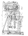
- the device according to the invention is mounted in a frame 1, substantially comprising a central column 2 and a horizontal frame plate 3, supported on legs 4.
- a driving shaft 5 is supported by means of ball bearings 6, which shaft 5 is driven by a not-drawn motor and drives the various knives by means of a V-pulley 7, which knives are drawn in fig. 3.
- These knives are circular-saw-shaped and can otherwise be provided with an own driving motor, for instance an electromotor or a hydraulic motor.
- a hub 8 is mounted by means of conical roller bearings 9, said hub 8 driving an upper plate 10 which is supported on the hub 8 by a lower ring 11 and an upper ring 12 and a number of support rods 13.
- the hub 8 is driven by a motor with reduction mechanism 14, driving the hub 8 via chain wheels 15 and 16 and a not-drawn chain.
- a number of processing devices 18 are supported by means of supports 17 and 17', said processing devices essentially comprising a processing arm 19, and adjustment mechanism 20 and a stretching mechanism 21.
- the processing arm 19 is rotatably mounted in the supports 17 by means of ball bearings 22 and 23.
- a slidable blocking pin 24 is supported in the supports 17 and 17', which is moreover guided on the processing arm 19 by means of a guide arm 25 secured on the blocking pin 24, and a guide ring 26.
- a ring 27 is mounted on the blocking pin 24, whereas between the support 17 and the ring 27 a pressure spring 28 is mounted on the pin 24, which tries to press the pin 24 in fig. 1 to the right.
- the guide arm is at its free end provided with a rotatable roll 29, which can cooperate with three deblocking cams 30, 31 and 32, which are all uniform, and one deblocking cam 33 which is longer than the first three cams. The meaning thereof will be elucidated hereafter.
- the deblocking cams 30-33 are mounted on the lower plate 3 of the frame 1.
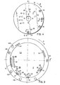
- an adjusting and blocking disc 34 is mounted (vide fig. 4), in which four blocking holes 35, 36, 37 and 38 are applied, according to the number of deblocking cams 30-33.
- the blocking pin 24 can engage in the four blocking holes 35-38 in the disc 34, the first hole 35 of which corresponds to the vertical starting position A of the processing device 18, drawn in the fig. 1, 2, 3 and 4, and the other holes 36, 37 and 38 subsequently correspond to an angle of rotation of the processing device 18 over 56,5 0 , 90o and 123,5 from the vertical starting position A, in clockwise direction (vide arrow B in fig. 4), seen in radial direction from the inside.
- two axial adjusting pins 39 and 40 are mounted, in which, starting from the vertical starting position A in fig. 4, the adjusting pin 39 is displaced in clockwise direction over an angle of 165 0 and the adjusting pin 40 over an angle of 90 0 in the same direction.
- these adjusting pins cooperate with fixed adjusting cams 41, 42 and 43 which are secured to the lower plate 3 as will be further elucidated hereunder (vide the fig. 3 and 6-8).
- a crown of adjusting pins 45-52 is mounted, in which, starting from the vertical starting position A in fig. 4, the pin 45 is displaced in clockwise direction over an angle of 225 0 and the pins 45, 46, 47 etc. each have a mutual angular distance of about 30 0 .
- these adjusting pins 45-52 cooperate with an adjusting cam 44, as will be further elucidated on the basis of the fig. 3 and 9.
- the device according to the invention can, seen in plan view, be devided into four quadrants I, II, III and IV of each 90 0 (vide fig. 3).
- the bird is preferably placed and stretched on the stretching mechanism 21, in the second quadrant II, in the third quadrant III, and in a part of the fourth quadrant IV the slaughtered bird is cut in nine pieces of about the same weight, whereas in the remaining part of the fourth quadrant the stretching mechanism 21 is opened, and the loose portions of the bird are for instance received on a conveyor belt, placed beneath the fourth quadrant.
- the first deblocking cam 30 is positioned at an angle of rotation of the processing arm 19 of about 32°, before which cam the stretching mechanism 21 is still vertical (position A in fig. 4).
- the deblocking cam 30 presses the arm and therewith the locking pin 24 back from the hole 35 in the disc 24.
- the adjusting pin 39 runs into the adjustment slot 53 of the first adjusting cam 41, which is also positioned at an angle of rotation of about 32 0 , the adjusting disc 34 and therewith the processing device 18 being rotated, clockwise over an angle of 56,5° in the direction B, seen from outside in radial direction after which the first deblocking cam 30 releases the blocking pin 24, and the latter grips into the second hole 36 in the disc 34.
- the second deblocking cam 31 is positioned at an angle of rotation of about 87 0 in which the blocking pin 24 is retracted in the above-described manner.
- the second adjusting cam 42 is also positioned at an angle of rotation of about 87°. Therewith the second adjusting pin 40 runs into the adjusting slot 54 of the second adjusting cam 42 and the processing device 18 is rotated over an angle of 33,5° in the direction B, after which the cam 31 releases the pin 24 and the latter grips into the third hole 37, the processing device 18 and the stretching mechanism 21 respectively being rotated totally about an angle of 90 0 in the direction B from the vertical starting position A.
- the third deblocking cam 32 is positioned at an angle of rotation of about 127 0 , the blocking pin 24 being retracted and the third adjusting cam 43 being positioned at an angle of rotation of also about 127 0 .
- the second adjusting pin 40 runs into the adjusting slot 55 of the third adjusting cam 43 and the processing device 18 is once again rotated over an angle of 33,5 in the direction of the arrow B, after which the cam 32 releases the pin 24 and the latter grips into the fourth hole 38 in the disc 34.
- the fourth deblocking cam 33 is positioned at an angle of rotation of about 172 0 of the processing arm 19, the blocking pin 24 being retracted.
- the fourth adjusting cam 44 is also positioned at an angle of rotation of about 172°, after which the last two adjusting pins 52 and 51 of the crown 45-52 move in a horizontal plane to the horizontal plane 56 of the fourth adjusting cam 44, consisting of a gear rack with seven teeth holes 57, the crown of adjusting pins rolling-off as a pinion on the gear rack and the cam 58 urging.the first adjusting pin 45 of the crown in upward direction.
- the processing device 18 is thereby further rotated over an angle of 236,5 0 up to the starting position A, after which the blocking pin 24 is released by the fourth deblocking cam 33 and the pin 24 grips again into the first blocking hole 35.
- the configuration of the deblocking cam is drawn, in which the cams30, 31 and 32 are uniform, have the same size and are constructed in straight manner.
- the cam 33 can be curved according to the circle of rotation of the roller 29 on the blocking pin 24, is longer than the cams 30, 31 and 32 and is provided with a rising face 59 and a falling face 60 just like the deblocking cams 30, 31 and 32.
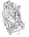
- the stretching mechanism is mounted on a hub 61 at the end of the processing arm 19, fig. 1.
- the stretching mechanism 21 is provided with a rectangular frame 61', on which at the upper side the lever 62 is mounted, which is pivotable on a shaft 63 and which is connected to the frame 61' by means of a tension spring 64 at the side facing the column 2.
- the lever 62 is double and at the other end of the two arms 62' and 62'' provided with U-shaped suspension hooks 65 and 66, in which the bird is hanged at the knee joints.
- the lever 62 can be provided with an adjustable stop, for instance a screw bolt in a transverse piece between the arms 62' and 62" of the U-shaped lever 62, said screw bolt being provided with a safety nut and engaging the upper side of the frame 61'.
- an adjustable stop for instance a screw bolt in a transverse piece between the arms 62' and 62" of the U-shaped lever 62, said screw bolt being provided with a safety nut and engaging the upper side of the frame 61'.
- the position of the suspension hooks 65 and 66 can be adapted to the size of the bird and the pulling force exerted on the bird by the suspension hooks is restricted to a certain maximum.
- a shaft 67 is mounted on which two pairs of support arms 68, 69 and 70, 71 are supported.
- the support arms are kept at the correct distance from each other and in the frame 61' by means of distance sleeves 72, 73.
- the support arms 69, 68 are at their free ends provided with support plates 74 and 75 resp., fig. 2, which press against the sides of the rumps of the bird.
- retaining plates 76 and 77 are mounted, which are supported by means of sleeves 78 and 79 on the arms 68, 69 and are adjustably mounted on the arms 68 and 69 by means of bolt 80, 81.
- Said retaining plates 76 and 77 press against the upper side of the rumps of the bird such that the legs of the bird, when they are cut with one of the knives, cannot be drawn further upwardly by the lever 62.
- the support arms 70 and 71 are at their free ends provided with support plates 82 and 83, fig. 2, engaging beneath the wings with the body of the bird.
- transverse grippers 84 and 85 are mounted on the support arms70 and 71, said grippers engaging behind the backbone of the bird.
- the grippers 84, 85 are mounted on the support arms 70 and 71 in the configuration of a lying U.
- a back support 86 is mounted by means of bolts through the holes 87 and 88, which bolts are screwed in the frame 61', vide the fig. 1 and 2.
- the back support 86 is in the centre provided with a longitudinal slot 89, in which the knife for cutting the bird in two halves is moving.
- the back support 86 is furthermore provided with a recess 90, in which the knife for cutting the entire legs can move, with two lateral slots 91 and 92, in which the support arms 70, 71 can be received when stretching the bird and with a bore 93, in which a shaft 94 for pivotable wing clamps 95 and 96 is supported, fig. 2, which engage over the wings of the bird.
- These wing clamps are mounted on sleeves 97 and 98, on which arms 9 9 and 100 are mounted which are provided with a longitudinal slot 101, 102, the function of which will be further elucidated hereafter.
- a slidable rod 103 is supported in slide bearings 104 and 105, fig. 1 and 2, on which rod a cam plate 106 is fixed with bolts, projecting through holes 107 and 108 in the cam plate 106 and are screwed in holes in the rod 103 which are provided with screw thread (fig. 13).
- the cam plate 106 is provided with a pair of cam slots 109 and 110 positioned in the shape of a V, through which the upper support arms 68 and 69 project.
- cam strip 111, 112 is outwardly pivotable against spring force, for instance by means of a torsion spring which is mounted on a shaft which in turn is mounted in a hole 113, 114, for instance with a nut on screw thread on the shaft.
- the cam strips 111 and 112 are provided with a pin 115, 116, which is movable in a slot 117, 118 in the cam plate 106 and pressed against the most inward end of the slot 117, 118 by the torsion spring. In this position of the cam strips 111 and 112 their inner edge is substantially positioned in the extension of the outer edge of the cam slots 109 and 110 and the cam strips cover the broader portion 109' and 110' of the cam slots 109 and 110.
- the cam plate 106 In the vicinity of the lower side the cam plate 106 is provided with a pair of cam slots 119 and 120 positioned in the shape of a V, through which the lower support arms 70 and 71 project. Furthermore in the side faces of the cam plate 106 a hole 121 and 122 provided with screw thread is bored, in which a bolt 123 and 124 resp. is screwed, on the head of which a nylon roller 125 and 126 resp. is rotatably supported. Said nylon rollers 125 and 126 grip into the longitudinal slots 101 and 102 in the actuating arms 99 and 100 of the pivotable wing clamps 95 and 96.
- a pair of nylon rollers 130 and 121 are supported by means of sleeves 128 and 129, whereas on the projecting inner end of the transverse shaft 127 a third nylon roller or cam 132 is mounted, fig. 1.
- a U-shaped lever 134 is pivotably supported on a shaft 135, which lever at the upper side is connected to the frame 61' by a tension spring 136 and at the lower side carries an arm 137 at the one leg of the U, in which a hole 138 is mounted which in the operative position of the stretching mechanism 21 engages with the hole 138 over the nylon roller or cam 132 on the transverse shaft 127 of the slidable rod 103.
- the lever 135 carries an unlocking pin 139 at the other leg of the U.
- an unlocking cam 140 in the quadrant IV and a rising cam 141 in the quadrant I are mounted on the frame 1 of the device, which cooperate with the unlocking pin 139 and the nylon rollers 130 and 131 resp. at the lower side of the slidable rod 103, on which the cam plate 106 for the operation of the pairs of support arms 68, 69 and 70, 71 and the pivotable wing clamps 95 and 96 is mounted.
- the stretching mechanism 21 At the outer side of the pivotable wing clamps 95 and 96 fixed wing hooks 142 and 143 are mounted on the stretching mechanism 21, which facilitate and improve the positioning and stretching of a bird on the stretching mechanism 21 (fig. 2).
- the knives are provided with drive motors of themselves, electrical or hydraulic, or they are centrally driven from the V-pulley 7 (fig. 5).
- the knives are mounted in supports (not drawn), which are universally adjustable, so that each knife is optimally adjustable.
- the knife 144 for cutting the breast is placed on the dividing line between the quadrant I and the quadrant II, where the angle of rotation of the processing device 18 is held at 0 0 .
- the second knife 145 for cutting the_one wing is placed at an angle of rotation of 65 0 in clockwise direction, the third knife 146 for cutting the bird lengthwise in two halves on an angle of rotation of 110 , the fourth knife 147 for cutting the other wing on an angle of rotation of 145°, the fifth knife 148 for cutting off the complete legs on an angle of rotation of 200° and the sixth knife 149 for cutting off the underlegs of the rumps on an angle of rotation of 220 0 .
- the processing device 18 passes the first knife 144 with the stretching mechanism in vertical position A (fig. 4), by which the breast of the bird is being cut off.
- the first knife stands substantially vertically, but inclines backwardly at an angle of 5 and has a free running angle in the direction of rotation D of 8°.
- the processing arm then rotates alongside the second deblocking cam 31 and the second adjusting cam 42 and the stretching mechanism 21 are being rotated further over an angle of 33,5 in arrow direction B, by which the stretching mechanism 21 comes to lie horizontally.
- the bird is cut lengthwise in two halves by the third knife 146, which also lies at a horizontal level, and which is positioned at an angle of rotation of 110 0 .
- a centering member for the breast bone of the bird can be positioned on the frame 1 of the device, which comprises two rolls, mounted on a vertical axle, which are provided with a cone-shaped portion at the sides that are facing each other, so that a V-shaped centering groove is formed for the breast bone of the bird.
- the processing arm passes the third deblocking cam 32 and the third adjusting cam 43, by which the stretching mechanism 21 is rotated again over an angle of 33,5° in the arrow direction B, so that the stretching mechanism is in total rotated over an angle of 123,5 in the arrow direction B.
- the fourth knife 147 which also lies at a horizontal level and is disposed on an angle of rotation of 145 0 , cuts off the other wing of the bird.
- the stretching mechanism 21 is rotated further in the arrow direction B to the position A according to fig. 4, over an angle of rotation of 236,5 0 in the way as described above, by which the stretching mechanism is again vertically.
- the fifth knife 148 is inclined downwardly at an angle of rotation of + 45 0 with respect to the horizontal level and is positioned at an angle of rotation of 200 0 in the arrow direction D.
- the fifth knife cuts off the entire legs of the bird.
- the stretching mechanism keeps standing in the vertical position A and the sixth knife 149 lies in a horizontal level, it is positioned at an angle of rotation of 220 0 in the arrow direction D of the processing arm 19 and cuts off the under-legs from the rumps of the bird.
- the stretching mechanism 21 passes the unlocking cam 140, by which the cam 140 pushes the unlocking pin 139 of the lever 134 (fig. 1) upwardly, the arm 137 moves away from the roll 132 and the rod 103 moves downwardly together with the cam plate 106 because of their own weight, by which the support arms 68, 69 and 70, 71 and also the pivotable wing clamps 95, 96 are being opened by the cam slots 109, 110 and 119, 120 and the rolls 126 respectively and the parts of the bird that are no longer held fall out of the stretching mechanism 21, by which the under-legs are being pushed out of the suspension hooks 65 and 66 with a guide.
- the broader parts 109' and 110' of the cam slots 109, 110 have the purpose of making possible a widthwise variable position of the support arms 68 and 69, so that the birds with variable weight and size can be stretched.
- Six cutting devices are used with the above described device according to the invention, by which the bird can be cut in nine separate pieces. Depending on the desired number of pieces one or more cutting devices can be placed out of action by dismounting the knife or the entire cutting device.
- the device according to the invention can also be embodied as an oval machine, which comprises two straight frame parts, that are connected to each other by two semi-circular parts of the frame, by which the processing devices 18 are being moved alongside the straight parts and the semi-circular parts of the frame, for instance with the aid of a driving chain.
- the frame of the device could also be embodied as a straight frame, in which the processing devices 18 can be led alongside the guides in the straight frame with the aid of for instance a driving chain.
Priority Applications (1)
| Application Number | Priority Date | Filing Date | Title |
|---|---|---|---|
| AT81200079T ATE3937T1 (de) | 1980-01-23 | 1981-01-22 | Vorrichtung zum durchschneiden von geschlachtetem gefluegel in separate stuecke. |
Applications Claiming Priority (2)
| Application Number | Priority Date | Filing Date | Title |
|---|---|---|---|
| NL8000424 | 1980-01-23 | ||
| NL8000424A NL8000424A (nl) | 1980-01-23 | 1980-01-23 | Inrichting voor het doorsnijden van geslacht gevogelte. |
Publications (2)
| Publication Number | Publication Date |
|---|---|
| EP0033177A1 true EP0033177A1 (fr) | 1981-08-05 |
| EP0033177B1 EP0033177B1 (fr) | 1983-06-29 |
Family
ID=19834730
Family Applications (1)
| Application Number | Title | Priority Date | Filing Date |
|---|---|---|---|
| EP81200079A Expired EP0033177B1 (fr) | 1980-01-23 | 1981-01-22 | Appareil de découpage de volailles abattues en morceaux séparés |
Country Status (12)
| Country | Link |
|---|---|
| US (2) | US4406037A (fr) |
| EP (1) | EP0033177B1 (fr) |
| JP (1) | JPS6018371B2 (fr) |
| AT (1) | ATE3937T1 (fr) |
| AU (1) | AU540291B2 (fr) |
| BR (1) | BR8100339A (fr) |
| CA (1) | CA1147914A (fr) |
| DE (1) | DE3160498D1 (fr) |
| DK (1) | DK157160C (fr) |
| NL (1) | NL8000424A (fr) |
| NZ (1) | NZ196079A (fr) |
| ZA (1) | ZA81485B (fr) |
Cited By (1)
| Publication number | Priority date | Publication date | Assignee | Title |
|---|---|---|---|---|
| EP0931459A1 (fr) * | 1998-01-21 | 1999-07-28 | Mayekawa Mfg Co.Ltd. | Procédé et dispositif de désossage automatique de la moitié supérieure de carcasses de volailles |
Families Citing this family (44)
| Publication number | Priority date | Publication date | Assignee | Title |
|---|---|---|---|---|
| NL8200252A (nl) * | 1982-01-25 | 1983-08-16 | Markert Heinrich Willy | Werkwijze en inrichting voor het in delen snijden van geslachte dieren. |
| US4505002A (en) * | 1983-01-06 | 1985-03-19 | Tieleman Edward J | Stretching mechanism of a device for cutting slaughtered poultry |
| US4536919A (en) * | 1983-03-18 | 1985-08-27 | Cagles', Inc. | Breast processor |
| NL188448C (nl) * | 1983-05-20 | 1992-07-01 | Systemate Bv | Delenmachine. |
| US4559672A (en) * | 1983-09-02 | 1985-12-24 | Hazenbroek Jacobus E | Poultry cut-up machine |
| US4557015A (en) * | 1983-10-06 | 1985-12-10 | Thurston Dodd | Poultry halving machine |
| US4745658A (en) * | 1984-01-20 | 1988-05-24 | Automated Packaging Systems, Inc. | Poultry holding mechanism with improved wing hooks |
| US4575901A (en) * | 1984-01-20 | 1986-03-18 | Automated Packaging Systems, Inc. | Poultry holding mechanism with improved wing hooks |
| US4715092A (en) * | 1985-01-04 | 1987-12-29 | Automatic Packaging Systems, Inc. | Apparatus and method for cutting slaughtered poultry into separate pieces |
| US4589165A (en) * | 1985-01-04 | 1986-05-20 | Automated Packaging Systems, Inc. | Apparatus and method for cutting slaughtered poultry into separate pieces |
| US4651506A (en) * | 1985-01-04 | 1987-03-24 | Automated Packaging Systems, Inc. | Packaging apparatus and method |
| USRE32963E (en) * | 1985-01-04 | 1989-06-27 | Automated Packaging Systems, Inc. | Packaging apparatus and method |
| US4669148A (en) * | 1985-01-23 | 1987-06-02 | Simon-Johnson, Inc. | Machine for cutting up poultry into a number of pieces |
| FR2593675B1 (fr) * | 1986-01-31 | 1989-08-25 | Bruyere Jean Claude | Installation de decoupe automatique des membres de volailles et animaux similaires |
| US5154664A (en) * | 1990-10-29 | 1992-10-13 | Hazenbroek Jacobus E | Keel bone cutter with fat remover |
| DE69507012T2 (de) * | 1994-01-18 | 1999-06-10 | Capital Formation Inc | Vorrichtung zum verpacken von geflügel und anderen gegenständen |
| US5782056A (en) * | 1994-01-18 | 1998-07-21 | Delaware Capital Formation, Inc. | Packaging apparatus for removing a product from a continuously moving conveyor and sealing said product in a bag with a closure |
| US6383069B1 (en) | 1998-02-20 | 2002-05-07 | Stork Gamco Inc. | Methods and apparatus for performing processing operations on a slaughtered animal or part thereof |
| US6190250B1 (en) | 1998-02-20 | 2001-02-20 | Stork Gamco Incorporated | Method and apparatus for performing processing operations on a slaughtered animal or part thereof |
| US7004830B2 (en) | 1998-07-16 | 2006-02-28 | Stork Pmt B.V. | Method and device for processing poultry |
| NL1009670C2 (nl) | 1998-07-16 | 2000-01-18 | Stork Pmt | Werkwijze en inrichting voor het bewerken van gevogelte. |
| US8157625B2 (en) | 2010-01-26 | 2012-04-17 | Foodmate Bv | Method and apparatus for collecting meat from an animal part |
| US8632380B2 (en) | 2010-01-26 | 2014-01-21 | Foodmate B.V. | Method and apparatus for removing a sleeve of meat from an animal part having bone with knuckles on each of its opposite ends |
| US8789684B2 (en) | 2010-04-19 | 2014-07-29 | Foodmate Bv | Rotatable article support for a conveyor |
| NL2004574C2 (en) | 2010-04-19 | 2011-10-20 | Foodmate B V | Rotatable article support for a conveyor. |
| NL2006075C2 (en) | 2011-01-26 | 2012-07-30 | Foodmate B V | Rotationally indexed article support for a conveyor system having an alignment station. |
| NL2004573C2 (en) | 2010-04-19 | 2011-10-20 | Foodmate B V | Turning block alignment. |
| US8757354B2 (en) | 2010-04-19 | 2014-06-24 | Foodmate Bv | Turning block alignment |
| US8727839B2 (en) | 2011-01-21 | 2014-05-20 | Foodmate Bv | Poultry wing cutter for narrow pitch poultry lines |
| US8267241B2 (en) | 2011-01-26 | 2012-09-18 | Foodmate Bv | Rotationally indexed article support for a conveyor system having an alignment station |
| KR101966469B1 (ko) | 2011-01-26 | 2019-04-05 | 푸드메이트 비.브이. | 동물의 대퇴부들로부터 고기를 분리하고 수집하기 위한 동물의 대퇴부들을 발골하는 방법 및 이를 수행하기 위한 장치 |
| US8882571B2 (en) | 2011-01-26 | 2014-11-11 | Foodmate Bv | Method of deboning animal thighs for separating and collecting meat therefrom and apparatus for performing the method |
| US8430728B2 (en) | 2011-02-14 | 2013-04-30 | Foodmate Bv | Special cut poultry wing cutter |
| US8888569B2 (en) | 2011-09-26 | 2014-11-18 | Tyson Foods, Inc. | Big poultry cut-up method |
| US8727840B2 (en) | 2012-04-30 | 2014-05-20 | Tyson Foods, Inc. | Method of cutting a pork loin |
| NL2009033C2 (en) | 2012-06-19 | 2013-12-23 | Foodmate B V | Weighing method and apparatus. |
| US8808068B2 (en) | 2012-10-29 | 2014-08-19 | Foodmate Bv | Method of and system for automatically removing meat from an animal extremity |
| NL2009718C2 (en) | 2012-10-29 | 2014-05-01 | Foodmate B V | Method of mechanically removing skin from animal parts. |
| US9078453B2 (en) | 2013-11-01 | 2015-07-14 | Foodmate B.V. | Method and system for automatically deboning poultry breast caps containing meat and a skeletal structure to obtain breast fillets therefrom |
| US8961274B1 (en) | 2013-12-18 | 2015-02-24 | Foodmate Bv | Selective tendon cutter and method |
| US10244769B2 (en) | 2014-08-07 | 2019-04-02 | Tyson Foods, Inc. | Method of cutting a pork loin and a boneless pork loin product |
| CN109673711A (zh) * | 2018-12-27 | 2019-04-26 | 广州富港万嘉智能科技有限公司 | 一种家禽传送装置及一种家禽加工设备 |
| CN109673710A (zh) * | 2018-12-27 | 2019-04-26 | 广州富港万嘉智能科技有限公司 | 一种家禽加工设备 |
| CN114600936B (zh) * | 2022-05-16 | 2022-07-29 | 河南科技学院 | 一种禽肉切割机 |
Citations (1)
| Publication number | Priority date | Publication date | Assignee | Title |
|---|---|---|---|---|
| US3950820A (en) * | 1974-01-24 | 1976-04-20 | Duncan Creations, Inc. | Poultry cutter |
Family Cites Families (32)
| Publication number | Priority date | Publication date | Assignee | Title |
|---|---|---|---|---|
| US2941238A (en) * | 1960-06-21 | reeves | ||
| US1536782A (en) * | 1924-07-12 | 1925-05-05 | Cincinnati Butchers Supply Co | Method of trimming heads and apparatus therefor |
| US2643778A (en) * | 1948-12-30 | 1953-06-30 | American Can Co | Conveyer mechanism with article turning units |
| US2957198A (en) * | 1958-08-25 | 1960-10-25 | Merchants Poultry Co | Machine for cutting poultry and the like |
| US3132373A (en) * | 1961-09-13 | 1964-05-12 | Jr William F Altenpohl | Poultry shackle for overhead conveyor and carriage assembly |
| US3722032A (en) * | 1968-03-26 | 1973-03-27 | Pillsbury Co | Apparatus for cutting and removing meat from bones |
| US3518717A (en) * | 1968-06-13 | 1970-07-07 | Us Agriculture | Rigid turkey shackle and positioning device |
| US3564644A (en) * | 1969-12-08 | 1971-02-23 | David T Cannon | Automatic poultry breast cutter |
| US3665553A (en) * | 1970-04-07 | 1972-05-30 | Avi Simplot Inc | Keel bone extractor for poultry products |
| US3624863A (en) * | 1970-05-08 | 1971-12-07 | Geno N Gasbarro | Poultry cutting apparatus |
| US3675272A (en) * | 1970-08-26 | 1972-07-11 | Henry Neil Schacht | Method of cutting and packing poultry |
| US3787926A (en) * | 1972-05-24 | 1974-01-29 | Pillsbury Co | Apparatus for cutting and packing poultry |
| US3916484A (en) * | 1973-10-05 | 1975-11-04 | Raymond A Kennedy | Method and apparatus for automatic carcass cutting |
| US3943600A (en) * | 1974-05-06 | 1976-03-16 | Campbell Soup Company | Apparatus and process for cutting chicken |
| US3946461A (en) * | 1975-01-06 | 1976-03-30 | Victor F. Weaver, Inc. | Poultry breast sectioning machine |
| US4083083A (en) * | 1975-06-05 | 1978-04-11 | Duncan Creations, Inc. | Machine for cutting poultry into selectively variable portions |
| CA1017509A (fr) * | 1975-06-06 | 1977-09-20 | Eric R.L. Baker | Machine a debiter la carcasse de volaille |
| US4016624A (en) * | 1975-10-17 | 1977-04-12 | Victor F. Weaver, Inc. | Poultry cut-up machine |
| US4067085A (en) * | 1976-02-09 | 1978-01-10 | Gasbarro Geno N | Automatic poultry cutting apparatus |
| US4136421A (en) * | 1977-09-22 | 1979-01-30 | Gordon Johnson Company | Method and apparatus for opening the body cavity of poultry |
| US4178659A (en) * | 1977-10-31 | 1979-12-18 | Stork Gamco, Inc. | Transfer apparatus for poultry processing conveyor |
| US4184229A (en) * | 1978-03-06 | 1980-01-22 | Beatrice Foods Co. | Device for processing poultry backs |
| US4214345A (en) * | 1978-08-23 | 1980-07-29 | Duncan Creations, Inc. | Machine for severing poultry into predetermined portions |
| US4251901A (en) * | 1979-07-20 | 1981-02-24 | Holly Farms Poultry Industries, Inc. | Apparatus and method for splitting poultry breasts |
| US4262387A (en) * | 1979-09-10 | 1981-04-21 | Simon-Johnson Inc. | Method and apparatus for eviscerating poultry |
| US4271561A (en) * | 1979-09-11 | 1981-06-09 | Lewis Eugene J | Poultry dismembering apparatus |
| US4270243A (en) * | 1979-11-29 | 1981-06-02 | Lewis Eugene J | Poultry breast splitting apparatus |
| US4306335A (en) * | 1980-05-09 | 1981-12-22 | Hawk Charles A | Method and apparatus for cutting poultry |
| SE433424B (sv) * | 1980-06-24 | 1984-05-28 | Meyn Maschf | Styckningsanordning for faglar |
| US4373232A (en) * | 1981-01-28 | 1983-02-15 | Foster Poultry Farms | Poultry cutting machine |
| US4407046A (en) * | 1981-11-16 | 1983-10-04 | Precision Automation Co., Inc. | Poultry cutting apparatus |
| US4424608A (en) * | 1982-04-01 | 1984-01-10 | Victor F. Weaver, Inc. | Automatic poultry breast processing machine and method |
-
1980
- 1980-01-23 NL NL8000424A patent/NL8000424A/nl not_active Application Discontinuation
-
1981
- 1981-01-15 AU AU66248/81A patent/AU540291B2/en not_active Ceased
- 1981-01-21 DK DK027481A patent/DK157160C/da not_active IP Right Cessation
- 1981-01-22 US US06/227,515 patent/US4406037A/en not_active Ceased
- 1981-01-22 AT AT81200079T patent/ATE3937T1/de not_active IP Right Cessation
- 1981-01-22 NZ NZ196079A patent/NZ196079A/xx unknown
- 1981-01-22 DE DE8181200079T patent/DE3160498D1/de not_active Expired
- 1981-01-22 CA CA000369056A patent/CA1147914A/fr not_active Expired
- 1981-01-22 EP EP81200079A patent/EP0033177B1/fr not_active Expired
- 1981-01-22 BR BR8100339A patent/BR8100339A/pt not_active IP Right Cessation
- 1981-01-23 JP JP56008091A patent/JPS6018371B2/ja not_active Expired
- 1981-01-23 ZA ZA00810485A patent/ZA81485B/xx unknown
-
1985
- 1985-09-26 US US06/780,737 patent/USRE32697E/en not_active Expired - Lifetime
Patent Citations (1)
| Publication number | Priority date | Publication date | Assignee | Title |
|---|---|---|---|---|
| US3950820A (en) * | 1974-01-24 | 1976-04-20 | Duncan Creations, Inc. | Poultry cutter |
Cited By (2)
| Publication number | Priority date | Publication date | Assignee | Title |
|---|---|---|---|---|
| EP0931459A1 (fr) * | 1998-01-21 | 1999-07-28 | Mayekawa Mfg Co.Ltd. | Procédé et dispositif de désossage automatique de la moitié supérieure de carcasses de volailles |
| US6059648A (en) * | 1998-01-21 | 2000-05-09 | Mayekawa Mfg. Co., Ltd. | Automatic deboning method and apparatus for upper half of poultry carcass |
Also Published As
| Publication number | Publication date |
|---|---|
| JPS6018371B2 (ja) | 1985-05-10 |
| ZA81485B (en) | 1982-02-24 |
| ATE3937T1 (de) | 1983-07-15 |
| DK157160B (da) | 1989-11-20 |
| NL8000424A (nl) | 1981-08-17 |
| DE3160498D1 (en) | 1983-08-04 |
| USRE32697E (en) | 1988-06-21 |
| NZ196079A (en) | 1983-12-16 |
| JPS56113247A (en) | 1981-09-07 |
| AU540291B2 (en) | 1984-11-08 |
| BR8100339A (pt) | 1981-08-11 |
| DK27481A (da) | 1981-07-24 |
| US4406037A (en) | 1983-09-27 |
| DK157160C (da) | 1990-04-30 |
| EP0033177B1 (fr) | 1983-06-29 |
| CA1147914A (fr) | 1983-06-14 |
| AU6624881A (en) | 1981-07-30 |
Similar Documents
| Publication | Publication Date | Title |
|---|---|---|
| EP0033177A1 (fr) | Appareil de découpage de volailles abattues en morceaux séparés | |
| US4059868A (en) | Apparatus for cutting open a fowl | |
| DE69630178T2 (de) | Verfahren und Vorrichtung zum Bearbeiten von Schlachtgeflügel | |
| DE69618599T3 (de) | Ausnehmer | |
| DE2559683A1 (de) | Verfahren und vorrichtung zum trennen und transportieren je einer lappigen lage aus einem stapel | |
| DK168352B1 (da) | Apparat til flåning af fjerkræ | |
| JPH0156734B2 (fr) | ||
| EP0245543A1 (fr) | Dispositif à ouvrir par découpe le corps d'une volaille | |
| DE2756347C3 (de) | Vorrichtung zum Ausscheiden der Kloaka von Geflügel | |
| DE1779209A1 (de) | Ausweidungsvorrichtung fuer Gefluegel | |
| CA1080919A (fr) | Appareil et methode pour preparer la volaille a l'evisceration | |
| DE3049679T1 (de) | Apparatus for pulling-off the skin of sheep carcasses in slaugh tering | |
| US20220151248A1 (en) | A Slaughtered Pig Part Processing Plant, A Clamp Structure For Retaining A Slaughtered Pig Part, And A Method Of Retaining A Slaughtered Pig Part By A Clamp Structure | |
| EP0310713A1 (fr) | Procédé et appareil de découpage de volailles abattues | |
| US3571845A (en) | Chicken-slaughtering mechanism | |
| US20220159978A1 (en) | A Slaughtered Pig Part Processing Plant, And a Coupling for the Plant | |
| DE60215055T2 (de) | Vorrichtung zum abziehen einer socke oder dergleichen von einer form | |
| US3323164A (en) | Separation of poultry shanks from drumsticks | |
| EP0357843A1 (fr) | Dispositif pour transférer la volaille saignée | |
| DE69726699T2 (de) | Vorrichtung zum Herausschneiden und/oder Öffnen des Afters bei Geflügel während des Schlachtens | |
| DE2746350A1 (de) | Verfahren und vorrichtung zum abhaeuten von tierkadavern | |
| US5425668A (en) | Poultry slaughtering machine | |
| DE1285906B (de) | Vorrichtung zum vollstaendigen oder teilweisen Ausschneiden des Rueckenbeins haengender Schlachtkoerper | |
| DE659557C (de) | Maschine zum Zurichten von Fischen | |
| AT500269B1 (de) | Vorrichtung zum einschneiden von wursthüllen |
Legal Events
| Date | Code | Title | Description |
|---|---|---|---|
| PUAI | Public reference made under article 153(3) epc to a published international application that has entered the european phase |
Free format text: ORIGINAL CODE: 0009012 |
|
| AK | Designated contracting states |
Designated state(s): AT BE CH DE FR GB IT LI LU NL SE |
|
| 17P | Request for examination filed |
Effective date: 19810716 |
|
| RAP1 | Party data changed (applicant data changed or rights of an application transferred) |
Owner name: TIELEMAN B.V. |
|
| ITF | It: translation for a ep patent filed |
Owner name: ING. C. CORRADINI & C. S.R.L. |
|
| GRAA | (expected) grant |
Free format text: ORIGINAL CODE: 0009210 |
|
| AK | Designated contracting states |
Designated state(s): AT BE CH DE FR GB IT LI LU NL SE |
|
| PG25 | Lapsed in a contracting state [announced via postgrant information from national office to epo] |
Ref country code: SE Effective date: 19830629 |
|
| REF | Corresponds to: |
Ref document number: 3937 Country of ref document: AT Date of ref document: 19830715 Kind code of ref document: T |
|
| PG25 | Lapsed in a contracting state [announced via postgrant information from national office to epo] |
Ref country code: AT Effective date: 19830801 |
|
| REF | Corresponds to: |
Ref document number: 3160498 Country of ref document: DE Date of ref document: 19830804 |
|
| ET | Fr: translation filed | ||
| PG25 | Lapsed in a contracting state [announced via postgrant information from national office to epo] |
Ref country code: LU Free format text: LAPSE BECAUSE OF NON-PAYMENT OF DUE FEES Effective date: 19840131 |
|
| PLBE | No opposition filed within time limit |
Free format text: ORIGINAL CODE: 0009261 |
|
| STAA | Information on the status of an ep patent application or granted ep patent |
Free format text: STATUS: NO OPPOSITION FILED WITHIN TIME LIMIT |
|
| 26N | No opposition filed | ||
| ITTA | It: last paid annual fee | ||
| PGFP | Annual fee paid to national office [announced via postgrant information from national office to epo] |
Ref country code: BE Payment date: 19950103 Year of fee payment: 15 |
|
| PGFP | Annual fee paid to national office [announced via postgrant information from national office to epo] |
Ref country code: CH Payment date: 19950120 Year of fee payment: 15 |
|
| PGFP | Annual fee paid to national office [announced via postgrant information from national office to epo] |
Ref country code: DE Payment date: 19950130 Year of fee payment: 15 |
|
| PG25 | Lapsed in a contracting state [announced via postgrant information from national office to epo] |
Ref country code: LI Effective date: 19960131 Ref country code: CH Effective date: 19960131 Ref country code: BE Effective date: 19960131 |
|
| BERE | Be: lapsed |
Owner name: TIELEMAN B.V. Effective date: 19960131 |
|
| REG | Reference to a national code |
Ref country code: CH Ref legal event code: PL |
|
| PG25 | Lapsed in a contracting state [announced via postgrant information from national office to epo] |
Ref country code: DE Effective date: 19961001 |
|
| PGFP | Annual fee paid to national office [announced via postgrant information from national office to epo] |
Ref country code: GB Payment date: 19990121 Year of fee payment: 19 |
|
| PGFP | Annual fee paid to national office [announced via postgrant information from national office to epo] |
Ref country code: FR Payment date: 19990127 Year of fee payment: 19 |
|
| PG25 | Lapsed in a contracting state [announced via postgrant information from national office to epo] |
Ref country code: GB Free format text: LAPSE BECAUSE OF NON-PAYMENT OF DUE FEES Effective date: 20000122 |
|
| PGFP | Annual fee paid to national office [announced via postgrant information from national office to epo] |
Ref country code: NL Payment date: 20000131 Year of fee payment: 20 |
|
| GBPC | Gb: european patent ceased through non-payment of renewal fee |
Effective date: 20000122 |
|
| PG25 | Lapsed in a contracting state [announced via postgrant information from national office to epo] |
Ref country code: FR Free format text: LAPSE BECAUSE OF NON-PAYMENT OF DUE FEES Effective date: 20000929 |
|
| REG | Reference to a national code |
Ref country code: FR Ref legal event code: ST |
|
| PG25 | Lapsed in a contracting state [announced via postgrant information from national office to epo] |
Ref country code: NL Free format text: LAPSE BECAUSE OF EXPIRATION OF PROTECTION Effective date: 20010122 |
|
| NLV7 | Nl: ceased due to reaching the maximum lifetime of a patent |
Effective date: 20010122 |