EP0017144B1 - An apparatus for precisely moving a table - Google Patents
An apparatus for precisely moving a table Download PDFInfo
- Publication number
- EP0017144B1 EP0017144B1 EP80101576A EP80101576A EP0017144B1 EP 0017144 B1 EP0017144 B1 EP 0017144B1 EP 80101576 A EP80101576 A EP 80101576A EP 80101576 A EP80101576 A EP 80101576A EP 0017144 B1 EP0017144 B1 EP 0017144B1
- Authority
- EP
- European Patent Office
- Prior art keywords
- axial
- movable table
- movable
- drive means
- tables
- Prior art date
- Legal status (The legal status is an assumption and is not a legal conclusion. Google has not performed a legal analysis and makes no representation as to the accuracy of the status listed.)
- Expired
Links
Images

Classifications
-
- G—PHYSICS
- G03—PHOTOGRAPHY; CINEMATOGRAPHY; ANALOGOUS TECHNIQUES USING WAVES OTHER THAN OPTICAL WAVES; ELECTROGRAPHY; HOLOGRAPHY
- G03F—PHOTOMECHANICAL PRODUCTION OF TEXTURED OR PATTERNED SURFACES, e.g. FOR PRINTING, FOR PROCESSING OF SEMICONDUCTOR DEVICES; MATERIALS THEREFOR; ORIGINALS THEREFOR; APPARATUS SPECIALLY ADAPTED THEREFOR
- G03F7/00—Photomechanical, e.g. photolithographic, production of textured or patterned surfaces, e.g. printing surfaces; Materials therefor, e.g. comprising photoresists; Apparatus specially adapted therefor
- G03F7/70—Microphotolithographic exposure; Apparatus therefor
- G03F7/70691—Handling of masks or workpieces
- G03F7/70716—Stages
-
- B—PERFORMING OPERATIONS; TRANSPORTING
- B23—MACHINE TOOLS; METAL-WORKING NOT OTHERWISE PROVIDED FOR
- B23Q—DETAILS, COMPONENTS, OR ACCESSORIES FOR MACHINE TOOLS, e.g. ARRANGEMENTS FOR COPYING OR CONTROLLING; MACHINE TOOLS IN GENERAL CHARACTERISED BY THE CONSTRUCTION OF PARTICULAR DETAILS OR COMPONENTS; COMBINATIONS OR ASSOCIATIONS OF METAL-WORKING MACHINES, NOT DIRECTED TO A PARTICULAR RESULT
- B23Q1/00—Members which are comprised in the general build-up of a form of machine, particularly relatively large fixed members
- B23Q1/25—Movable or adjustable work or tool supports
- B23Q1/44—Movable or adjustable work or tool supports using particular mechanisms
- B23Q1/56—Movable or adjustable work or tool supports using particular mechanisms with sliding pairs only, the sliding pairs being the first two elements of the mechanism
- B23Q1/60—Movable or adjustable work or tool supports using particular mechanisms with sliding pairs only, the sliding pairs being the first two elements of the mechanism two sliding pairs only, the sliding pairs being the first two elements of the mechanism
- B23Q1/62—Movable or adjustable work or tool supports using particular mechanisms with sliding pairs only, the sliding pairs being the first two elements of the mechanism two sliding pairs only, the sliding pairs being the first two elements of the mechanism with perpendicular axes, e.g. cross-slides
- B23Q1/621—Movable or adjustable work or tool supports using particular mechanisms with sliding pairs only, the sliding pairs being the first two elements of the mechanism two sliding pairs only, the sliding pairs being the first two elements of the mechanism with perpendicular axes, e.g. cross-slides a single sliding pair followed perpendicularly by a single sliding pair
-
- Y—GENERAL TAGGING OF NEW TECHNOLOGICAL DEVELOPMENTS; GENERAL TAGGING OF CROSS-SECTIONAL TECHNOLOGIES SPANNING OVER SEVERAL SECTIONS OF THE IPC; TECHNICAL SUBJECTS COVERED BY FORMER USPC CROSS-REFERENCE ART COLLECTIONS [XRACs] AND DIGESTS
- Y10—TECHNICAL SUBJECTS COVERED BY FORMER USPC
- Y10T—TECHNICAL SUBJECTS COVERED BY FORMER US CLASSIFICATION
- Y10T74/00—Machine element or mechanism
- Y10T74/20—Control lever and linkage systems
- Y10T74/20207—Multiple controlling elements for single controlled element
- Y10T74/20341—Power elements as controlling elements
- Y10T74/20354—Planar surface with orthogonal movement only
Definitions
- This invention relates to an apparatus for precisely moving a table according to the introductory portion of claim 1 or 2, the apparatus being used in a step-and-repeat camera, a step-and-repeat projection printing apparatus, etc.
- the apparatus of step-and-repeat cameras etc. as above mentioned project and print photographically an integrated circuit pattern on a mask substrate or wafer which is usually coated with photoresist.
- a precisely movable X-Y table is provided, the mask substrate or wafer is installed thereon, and, while intermittently driving the table in the X- and Y-directions, the integrated circuit pattern is arrayed and printed on the entire area of the mask substrate or wafer.
- circuit patterns differing from one another be overlapped on a single wafer, at a positioning precision of approximately 0.2 pm, ordinarily 8 to 12 times or so. For this reason, the drive and movement of the X-Y movable table has to occur with an equal or higher positioning precision. Further, such X-Y movable table is required to execute high-speed positioning in order to enhance the productivity.
- a Y-directional movable table is stacked on an X-directional movable table and a driving system for the Y-directional movement including a motor, feed screws etc. is installed on the X-directional movable table.
- an X-Y movable table-- has- -been known, as shown in Fig. 1, wherein both X- and Y-driving systems are fixed to a rest frame (refer to "Kikai Sekkei (Machine Design)", vol. 14, No. 2, 1970, page 35).
- this structure however, in case where the movable table moves in the Y-axial direction, guide surfaces are both, the surfaces of an X-frame portion 1 and a Y-frame portion 2, so that the straightness of the moving direction is liable to be spoilt disadvantageously.
- the X-Y two-dimensional movable table as stated above incurs another disadvantage in contrast to the aforecited advantages. That is, strain energy which corresponds to the parellelism error between both the guide surfaces of the X-frame portion 1 and the Y-frame portion 2 in Fig. 1 is accumulated in the frame members etc., and this brings about such disadvantage that the yaw or the stick slip is caused. This is attributed to the frictional forces of the sliding parts.
- a further disadvantage is that the strain energy is gradually released to give rise to a phenomenon in which the movable table drifts at a very low speed of, for example, 0.1 to 0.5 pm/sec after the positioning thereof.
- a stage drive for a step-and-repeat camera which comprises a movable member and rectilinear drive means respectively disposed and fixed on X- and Y-coordinate axes.
- the movable member is constructed of an X-axial movable intermediate member named "cross" and the Y-axial movable stage itself.
- the movement of the cross is constrained to the X-direction by two colinear quartz guide blocks.
- the stage is also guided by a pair of quartz guide blocks mounted on the top surface of the cross in parallel to the Y-axis.
- Stage and cross are driven by drive systems with low backlash resulting inevitably from the use of movable mechanical members and air bearings. While the X-axis drive is attached to the cross through a slender flexible column which allows both, vertical and horizontal misalignment between the cross and the drive, the Y-axis drive is coupled directly to the stage through two air bearings and a guide bar attached to the stage.
- the object of the present invention is to provide an apparatus for precisely moving a table, which permits high-speed positioning and high- precision movement of the movable table.
- an apparatus which apparatus comprises a movable member constructed of an X-axial movable table and a Y-axial movable table, which tables are driven by respective rectilinear drive means and are coupled thereto by coupling means.
- said coupling means comprises a roller portion whose rotary shaft is fastened to a part of said Y-axial movable table and which serves for the Y-axial drive, and a member having an oblong opening extending in the X-axial direction, whose width is greater than the outside diameter of said roller portion.
- the coupling means is constructed of two rollers whose respective rotary shafts are fastened to a part of said Y-axial movable table, and a rod which extends in the X-axial direction and which is held between said two rollers with a backlash.
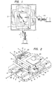
- FIG. 2 is a schematic perspective view showing an embodiment of this invention.
- three guide rails 4, 5 and 6 for an X-axis are provided on a base 3, and an X-axis movable table 7 slides with its load carried by the guide rails 4 and 6.
- sheets 8 made of a high polyer material for example, sliders made of ethylene tetrafluoride polymer or the like
- a high polyer material for example, sliders made of ethylene tetrafluoride polymer or the like
- Two yaw sliders 9 one of which does not appear in the figure) are disposed in the middle parts of the X-axis movable table 7, and are pushed against a side surface of the guide rail 5 by rollers 11 which are urged by leaf springs in advance. That is, the X-axis movable table 7 carries out a rectilinear motion along this guide rail 5.
- guide rails 12, 13 and 14 for a Y-axis are provided on the X-axis movable table 7, and a Y-axis movable table 15 for placing a workpiece or the like thereon carries out a rectilinear motion in the Y-axial direction in such a manner that the guide rail 13 is held between yaw sliders 16 and 17 and rollers 18 and 19.
- the rectilinear motion of a driving system which is not shown and which is made up of a combination of a D.C. servomotor, ball screws etc. is transmitted to the movable tables 7 and 15 through respective connecting rods (driving rods) 20 and 21 for the X- and Y-axes.
- the fore end part of the Y-axial connecting rod assembly 21 is provided with a driving frame 22 having an oblong opening, within which a roller portion (for example, bearing) 23 is constrained. Since a rotary shaft of the roller portion 23 is fixed onto the yaw slider 17, the motion of the connecting rod assembly 21 is transmitted to the Y-axial movable table 15.
- a roller portion for example, bearing
- the width of the oblong opening of the driving frame 22 is greater than the outside diameter of the roller portion 23, in other words, a backlash is provided between both the parts. Therefore, the Y-axial movable table 15 is guided by only the X-axial guide rail 5 without being restrained by the driving frame 22 and can be moved also in the X-axial direction at high precision without causing a yaw or spoiling the rectilinearity.
- a part 24 on the Y-axial movable table 15 is a workpiece (for example, glass substrate), and a part 25 is a reflector for a laser interference measuring instrument (not shown) which detects the position of the Y-axial movable table 15.
- the position control is carried out by a closed loop control which employs the laser interference measuring instrument as a position sensor.
- the position control with respect to the X-axis is the conventional linear position control, whereas in case of the Y-axis, the ordinary closed loop control incurs hunting and cannot achieve a good positioning accuracy on account of the existence of the backlash.
- Figure 3 is a diagram for explaining the Y-axial control.
- the axis of abscisses represents the positional deviation AY from a desired position O
- the axis of the ordinate represents the velocity command Vy for the D.C. servomotor.
- the D.C. servomotor is commanded to rotate at the maximum speed.
- 50 mm/s is the maximum speed.
- a reverse command is applied to the D.C. servomotor for, e.g., about 5 ms, and the driving frame 22 is retreated to prepare the backlash.
- Figure 2 may well be replaced by a construction as shown in Figure 4. More specifically, a rod 28 extending in the X-axial direction is disposed instead of the driving frame 22 at the fore ends of the Y-axial connecting rods 21, two rollers 23 and 23' have their respective rotary shafts fixed to a part of the Y-axial movable table 15, and the rod 28 is held between the rollers 23 and 23' with a backlash. Also in this case, the same effects as in the example of Figure 2 are attained.
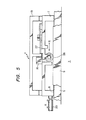
- FIG. 5 is a view for explaining an example of the mechanism for eliminating the problems, and shows a section parallel to the X-axis.
- the feature of this example consists in a weight lightening mechanism for the X-axial movable table 7 as is made up of a load relieving roller 26 and a spring 27 (for example made of a phosphor bronze plate). More specifically, the load relieving roller 26 is previously loaded in the gravitational direction by means of the spring 27 which has its fixed end on the X-axial movable table 7, and it is placed on the X-axial yaw guide 9 to relieve the load of the X-axial movable table 7 to the amount of the loaded component.
- the present invention is greatly effective when applied to workpiece moving tables of high speed and high precision, etc., which are used in semiconductor producing equipment such as step-and-repeat cameras and step-and-repeat projection printing apparatuses, and other precision type measuring instruments and precision machines.
Landscapes
- Engineering & Computer Science (AREA)
- Mechanical Engineering (AREA)
- Physics & Mathematics (AREA)
- General Physics & Mathematics (AREA)
- Machine Tool Units (AREA)
- Transmission Devices (AREA)
- Manipulator (AREA)
Applications Claiming Priority (2)
| Application Number | Priority Date | Filing Date | Title |
|---|---|---|---|
| JP41108/79 | 1979-04-06 | ||
| JP4110879A JPS55134414A (en) | 1979-04-06 | 1979-04-06 | Precise moving unit |
Publications (2)
| Publication Number | Publication Date |
|---|---|
| EP0017144A1 EP0017144A1 (en) | 1980-10-15 |
| EP0017144B1 true EP0017144B1 (en) | 1986-07-16 |
Family
ID=12599271
Family Applications (1)
| Application Number | Title | Priority Date | Filing Date |
|---|---|---|---|
| EP80101576A Expired EP0017144B1 (en) | 1979-04-06 | 1980-03-25 | An apparatus for precisely moving a table |
Country Status (4)
| Country | Link |
|---|---|
| US (1) | US4409860A (enExample) |
| EP (1) | EP0017144B1 (enExample) |
| JP (1) | JPS55134414A (enExample) |
| DE (1) | DE3071661D1 (enExample) |
Families Citing this family (86)
| Publication number | Priority date | Publication date | Assignee | Title |
|---|---|---|---|---|
| FR2501563B1 (fr) * | 1981-03-10 | 1986-07-18 | Sormel Sa | Manipulateur automatique |
| AU551402B2 (en) * | 1981-04-21 | 1986-05-01 | Tinsley Wire (Sheffield) Ltd. | Reinforcing strip for concrete pipe coatings |
| JPS5844144U (ja) * | 1981-09-16 | 1983-03-24 | 日本精工株式会社 | Xyテ−ブルの接続機構 |
| US4525852A (en) * | 1983-03-15 | 1985-06-25 | Micronix Partners | Alignment apparatus |
| NL8301033A (nl) * | 1983-03-23 | 1984-10-16 | Philips Nv | Stralingsapparaat met membraanaandrijving voor een objectdrager. |
| US4580892A (en) * | 1983-06-29 | 1986-04-08 | Dainippon Screen Mfg. Co., Ltd. | Contact printing apparatus |
| US4631382A (en) * | 1983-09-19 | 1986-12-23 | Mitsubishi Denki Kabushiki Kaisha | Bed for electrical discharge machining apparatus |
| JPS60232839A (ja) * | 1984-05-04 | 1985-11-19 | Hitachi Ltd | 直線状案内軌道の固定装置 |
| IT8521711U1 (it) * | 1985-05-03 | 1986-11-03 | O M G Snc | Struttura di supporto per caricatori di segnature e mili, atta a consentire che le segnature stesse, dal loro formato, vengano scaricate sempre con un lato disposto di un piano verticale prefissato |
| US4676492A (en) * | 1985-07-01 | 1987-06-30 | Shamir Arye H | Shallow X-Y table positioning device having large travel capability |
| FR2586853B1 (fr) * | 1985-08-30 | 1988-07-29 | Suisse Electronique Microtech | Dispositif de micropositionnement |
| US4866998A (en) * | 1985-09-20 | 1989-09-19 | Temple University Of The Commonwealth System Of Higher Education | Medical examination table with probe holder |
| US4729536A (en) * | 1986-11-04 | 1988-03-08 | Harry Scala | Anagraphic stand |
| DD297758A7 (de) * | 1987-03-13 | 1992-01-23 | ������@������������k�� | Positionierungseinrichtung fuer die herstellung von halbleiterbauelementen |
| US5040431A (en) * | 1988-01-22 | 1991-08-20 | Canon Kabushiki Kaisha | Movement guiding mechanism |
| US4971159A (en) * | 1988-04-12 | 1990-11-20 | G. G. B. Industries, Inc. | Micropositioner |
| US4972574A (en) * | 1988-06-08 | 1990-11-27 | Mamiya Denshi Co., Ltd. | Table driving apparatus |
| JPH0259494U (enExample) * | 1988-10-21 | 1990-05-01 | ||
| EP0366420A3 (en) * | 1988-10-28 | 1992-04-15 | Mamiya Denshi Co. Ltd. | Table driving apparatus |
| US5095258A (en) * | 1989-12-28 | 1992-03-10 | Mar Engineering, Inc. | Longitudinal motion error compensation apparatus method and apparatus for multiaxis CNC machine |
| JP2727368B2 (ja) * | 1990-01-04 | 1998-03-11 | 株式会社新川 | Xyテーブル |
| US5165296A (en) * | 1990-01-12 | 1992-11-24 | Ken Yanagisawa | Drive system |
| US5214976A (en) * | 1990-01-12 | 1993-06-01 | Ken Yanagisawa | Drive system |
| JPH0719693Y2 (ja) * | 1990-04-27 | 1995-05-10 | エヌティエヌ株式会社 | 移動テーブル |
| US5092193A (en) * | 1990-06-06 | 1992-03-03 | Ken Yanagisawa | Drive system |
| US5061039A (en) * | 1990-06-22 | 1991-10-29 | The United States Of America As Represented By The United States Department Of Energy | Dual axis translation apparatus and system for translating an optical beam and related method |
| JP2535248Y2 (ja) * | 1990-11-30 | 1997-05-07 | 日本トムソン株式会社 | Xyテーブル装置 |
| JPH0790437B2 (ja) * | 1992-05-12 | 1995-10-04 | 健 柳沢 | 2次元運動機構 |
| US5341709A (en) * | 1992-12-17 | 1994-08-30 | Speranza Specialty Machining | Portable vertical boring machine |
| US5341700A (en) * | 1992-12-17 | 1994-08-30 | Speranza Specialty Machining | X-Y movement mechanism |
| US7365513B1 (en) | 1994-04-01 | 2008-04-29 | Nikon Corporation | Positioning device having dynamically isolated frame, and lithographic device provided with such a positioning device |
| US5528118A (en) * | 1994-04-01 | 1996-06-18 | Nikon Precision, Inc. | Guideless stage with isolated reaction stage |
| US6989647B1 (en) * | 1994-04-01 | 2006-01-24 | Nikon Corporation | Positioning device having dynamically isolated frame, and lithographic device provided with such a positioning device |
| US5874820A (en) | 1995-04-04 | 1999-02-23 | Nikon Corporation | Window frame-guided stage mechanism |
| US6246204B1 (en) | 1994-06-27 | 2001-06-12 | Nikon Corporation | Electromagnetic alignment and scanning apparatus |
| US5730031A (en) * | 1994-08-24 | 1998-03-24 | Hewlett-Packard Company | Structure guidance and drive assembly for translation of a robotic picker assembly |
| US5623853A (en) * | 1994-10-19 | 1997-04-29 | Nikon Precision Inc. | Precision motion stage with single guide beam and follower stage |
| US6008500A (en) * | 1995-04-04 | 1999-12-28 | Nikon Corporation | Exposure apparatus having dynamically isolated reaction frame |
| TW318255B (enExample) | 1995-05-30 | 1997-10-21 | Philips Electronics Nv | |
| JP3709896B2 (ja) * | 1995-06-15 | 2005-10-26 | 株式会社ニコン | ステージ装置 |
| US5760564A (en) * | 1995-06-27 | 1998-06-02 | Nikon Precision Inc. | Dual guide beam stage mechanism with yaw control |
| DE19531676C1 (de) * | 1995-08-29 | 1996-11-14 | Hesse Gmbh | Vorrichtung zum Führungstoleranzausgleich bei Mehrachsenpositionierern |
| DE69719847T2 (de) * | 1996-05-16 | 2004-02-05 | Ebara Corp. | Verfahren und Vorrichtung zum Polieren von Werkstücken |
| JP3296976B2 (ja) * | 1996-10-14 | 2002-07-02 | 新日本工機株式会社 | 工作機械のテーブル操作装置及びその制御方法 |
| US5724893A (en) * | 1996-10-15 | 1998-03-10 | Taichung Machinery Works Co. Ltd. | Servo-type shaking table assembly |
| JP3884803B2 (ja) * | 1996-11-11 | 2007-02-21 | 株式会社三共製作所 | 2次元運動生成装置 |
| DE29805195U1 (de) * | 1998-03-21 | 1998-08-13 | Trumpf GmbH & Co., 71254 Ditzingen | Maschine zum Bearbeiten von plattenartigen Werkstücken, insbesondere von Blechen |
| US6193199B1 (en) * | 1998-07-15 | 2001-02-27 | Nanomotion, Inc. | Sample stage including a slider assembly |
| US6346710B1 (en) | 1998-08-31 | 2002-02-12 | Olympus Optical Co., Ltd. | Stage apparatus including displacement amplifying mechanism |
| US6152599A (en) * | 1998-10-21 | 2000-11-28 | The University Of Texas Systems | Tomotherapy treatment table positioning device |
| US6130490A (en) * | 1999-04-06 | 2000-10-10 | Nikon Corporation | X-Y stage with movable magnet plate |
| US6276676B1 (en) * | 1999-07-30 | 2001-08-21 | Excellon Automation Company | Manual registration pin alignment system |
| JP2001328043A (ja) * | 2000-05-24 | 2001-11-27 | Harmonic Drive Syst Ind Co Ltd | テーブル位置決め装置 |
| DE10028393B4 (de) * | 2000-06-13 | 2005-09-01 | System 3R International Ab | Nivelliervorrichtung |
| IT1320478B1 (it) * | 2000-06-30 | 2003-11-26 | Franco Sartorio | Macchina operatrice e dispositivo manipolatore installabile su talemacchina. |
| JP4366877B2 (ja) * | 2001-03-13 | 2009-11-18 | 株式会社デンソー | 自力移動ロボット装置 |
| US6781138B2 (en) * | 2001-05-30 | 2004-08-24 | Nikon Corp. | Positioning stage with stationary actuators |
| US6740998B2 (en) * | 2001-11-02 | 2004-05-25 | Advantest Corporation | Single motor, multi-axis stage |
| JP2005010120A (ja) * | 2003-06-23 | 2005-01-13 | Internatl Business Mach Corp <Ibm> | ポジショニングステージ |
| JP2005144487A (ja) * | 2003-11-13 | 2005-06-09 | Seiko Epson Corp | レーザ加工装置及びレーザ加工方法 |
| US7637487B2 (en) * | 2004-06-15 | 2009-12-29 | Thk Co., Ltd. | XY guide table |
| US7256891B2 (en) * | 2004-08-23 | 2007-08-14 | Beckman Coulter, Inc. | Sensor alignment apparatus for an analysis system |
| KR100711875B1 (ko) * | 2005-07-29 | 2007-04-25 | 삼성에스디아이 주식회사 | 유기 발광표시장치 제조용 석영 플레이트 지지장치 |
| JP4376225B2 (ja) * | 2005-11-29 | 2009-12-02 | 日本ベアリング株式会社 | テーブル装置 |
| ATE514802T1 (de) * | 2006-03-29 | 2011-07-15 | Applied Materials Gmbh & Co Kg | Vakuumtransportvorrichtung mit beweglicher führungsschiene |
| US20110102744A1 (en) * | 2006-10-10 | 2011-05-05 | Philip Saad | Camera support for cinematography equipment |
| US7794088B1 (en) * | 2006-10-10 | 2010-09-14 | Philip Saad | Camera support for cinematography equipment |
| US7854512B2 (en) * | 2007-02-22 | 2010-12-21 | Skyler M Tegland | Apparatus for mounting motion picture camera equipment |
| WO2008129983A1 (ja) * | 2007-04-16 | 2008-10-30 | Ulvac, Inc. | コンベアおよび成膜装置とそのメンテナンス方法 |
| CN102037552B (zh) * | 2008-05-19 | 2013-01-23 | 株式会社爱发科 | 平台 |
| US8556246B2 (en) * | 2008-06-27 | 2013-10-15 | Qem, Inc. | Low-profile X-Y table |
| US7883077B2 (en) * | 2008-06-27 | 2011-02-08 | QEM, Inc, | Low-profile X-Y table |
| US20100077877A1 (en) * | 2008-09-26 | 2010-04-01 | Ming-Hung Hsieh | Rotary micro-adjustment mechanism for a synchronous double-drive positioning platform |
| US8763999B2 (en) * | 2009-10-27 | 2014-07-01 | Applied Materials Israel, Ltd. | Stage structure for operation in vacuum |
| WO2012040705A2 (en) * | 2010-09-24 | 2012-03-29 | Rudolph Technologies, Inc. | Support for semiconductor substrate |
| US20120152042A1 (en) * | 2010-12-21 | 2012-06-21 | Chung-Shan Institute of Science and Technology, Armaments, Bureau, Ministry of National Defense | Multi-Dimensional Micro Driver |
| CN102554638B (zh) * | 2010-12-31 | 2016-06-29 | 富泰华工业(深圳)有限公司 | 定位机台 |
| JP5763936B2 (ja) * | 2011-03-01 | 2015-08-12 | カヤバ システム マシナリー株式会社 | 起震装置 |
| US9272442B2 (en) | 2012-12-31 | 2016-03-01 | Sunedison, Inc. | Methods for aligning an ingot with mounting block |
| US9950402B2 (en) * | 2012-12-31 | 2018-04-24 | Corner Star Limited | System and method for aligning an ingot with mounting block |
| EP2982472B1 (de) * | 2014-08-06 | 2017-09-13 | FESTO AG & Co. KG | Positioniersystem |
| KR101520401B1 (ko) * | 2015-01-13 | 2015-05-15 | 재단법인차세대융합기술연구원 | 이동 가능한 테이블 시스템 |
| CN104801994B (zh) * | 2015-05-07 | 2017-07-25 | 中铁十二局集团第七工程有限公司 | 钢板钻孔定位装置 |
| US10881561B2 (en) * | 2016-09-16 | 2021-01-05 | Fenton Mobility Products, Inc. | Shiftable assembly for a platform wheelchair lift |
| KR101866076B1 (ko) * | 2016-10-21 | 2018-06-11 | 현대자동차주식회사 | 변속기의 시프트레일 이송장치 |
| CN108214616B (zh) * | 2018-02-11 | 2024-03-15 | 深圳市裕同包装科技股份有限公司 | 一种用于v槽的加工设备 |
Family Cites Families (14)
| Publication number | Priority date | Publication date | Assignee | Title |
|---|---|---|---|---|
| US1760710A (en) * | 1929-01-25 | 1930-05-27 | Jesse J Mitchell | Multiple-control device |
| US2164412A (en) * | 1936-07-30 | 1939-07-04 | Siemens App Und Maschinen Gmbh | Navigating apparatus for instruction purposes |
| US2941136A (en) * | 1957-09-23 | 1960-06-14 | Micro Path Inc | Digital servomotor control system |
| US3124018A (en) * | 1961-07-07 | 1964-03-10 | gough | |
| US3188910A (en) * | 1962-06-25 | 1965-06-15 | Dietzgen Co Eugene | Projector viewer and image scanning assembly therefor |
| US3155383A (en) * | 1962-10-11 | 1964-11-03 | Link Division Of General Prec | Precision positioning apparatus |
| US3586273A (en) * | 1969-02-25 | 1971-06-22 | Jerome J Sloyan | Motor base with nonlubricated sliding carriage |
| US3638933A (en) * | 1970-08-10 | 1972-02-01 | Yosemite Lab | Precision x-y positioning table |
| US3790266A (en) * | 1970-10-24 | 1974-02-05 | Fuji Photo Film Co Ltd | Microfiche projecting apparatus |
| US3690642A (en) * | 1971-01-20 | 1972-09-12 | Saab Scania Ab | Means for confining a translatable member to straight line motion |
| US3743904A (en) * | 1972-05-01 | 1973-07-03 | Teledyne Inc | Precision positioning mechanism, particularly for positioning test probes and the like with respect to micro-electronic units |
| US3801090A (en) * | 1972-07-10 | 1974-04-02 | Gillen William F | Coordinate table |
| US3918167A (en) * | 1974-03-01 | 1975-11-11 | Gerber Scientific Instr Co | Apparatus for sensing relative movement of a work table and tool |
| JPS5650517Y2 (enExample) * | 1977-02-09 | 1981-11-26 |
-
1979
- 1979-04-06 JP JP4110879A patent/JPS55134414A/ja active Granted
-
1980
- 1980-03-25 DE DE8080101576T patent/DE3071661D1/de not_active Expired
- 1980-03-25 EP EP80101576A patent/EP0017144B1/en not_active Expired
- 1980-04-07 US US06/138,095 patent/US4409860A/en not_active Expired - Lifetime
Also Published As
| Publication number | Publication date |
|---|---|
| JPS5640852B2 (enExample) | 1981-09-24 |
| EP0017144A1 (en) | 1980-10-15 |
| US4409860A (en) | 1983-10-18 |
| DE3071661D1 (en) | 1986-08-21 |
| JPS55134414A (en) | 1980-10-20 |
Similar Documents
| Publication | Publication Date | Title |
|---|---|---|
| EP0017144B1 (en) | An apparatus for precisely moving a table | |
| US4648725A (en) | Guide mechanism | |
| DE69702601T2 (de) | Zweidimensionale balancierte positioniervorrichtung und mit dieser positioniervorrichtung ausgerüstete lithographische vorrichtung | |
| JP2960423B2 (ja) | 試料移動装置及び半導体製造装置 | |
| DE60032568T2 (de) | Positionierungsapparat und damit versehener lithographischer Apparat | |
| KR100512450B1 (ko) | 두개의물체홀더를가진이차원적으로안정화된위치설정장치와이런위치설정장치를구비한리소그래픽장치 | |
| DE3751515T2 (de) | Positioniervorrichtung. | |
| DE69937547T2 (de) | Geraet zur genauen hochgeschwindigkeits-positionierung | |
| US6937911B2 (en) | Compensating for cable drag forces in high precision stages | |
| KR100625625B1 (ko) | 기판, 스테이지 장치, 스테이지 구동 방법, 노광 장치 및노광 방법 | |
| DE69629087T2 (de) | Positionierungsgerät mit einem referenzrahmen für ein messsystem | |
| US5760564A (en) | Dual guide beam stage mechanism with yaw control | |
| US6449030B1 (en) | Balanced positioning system for use lithographic apparatus | |
| JP2631485B2 (ja) | 位置決め装置 | |
| US4744675A (en) | Moving mechanism | |
| EP0259776B1 (en) | Screen printing machine | |
| KR102676391B1 (ko) | 노광 장치, 노광 방법, 플랫 패널 디스플레이의 제조 방법, 및 디바이스 제조 방법 | |
| DE60314557T2 (de) | Verwaltung von Reaktionskräften in einem lithographischen System | |
| WO2003026838A1 (en) | Decoupled planar positioning system | |
| KR20170128602A (ko) | 노광 장치, 플랫 패널 디스플레이의 제조 방법, 디바이스 제조 방법, 및 노광 방법 | |
| US4563820A (en) | Aligning system | |
| JPH0434166B2 (enExample) | ||
| JPS6018918A (ja) | ステージ装置 | |
| US4595257A (en) | Support mechanism utilizing flexual pivots | |
| CN109116870B (zh) | 一种用于轨道检测的相机稳定平台 |
Legal Events
| Date | Code | Title | Description |
|---|---|---|---|
| PUAI | Public reference made under article 153(3) epc to a published international application that has entered the european phase |
Free format text: ORIGINAL CODE: 0009012 |
|
| AK | Designated contracting states |
Designated state(s): DE FR GB NL |
|
| 17P | Request for examination filed |
Effective date: 19810324 |
|
| GRAA | (expected) grant |
Free format text: ORIGINAL CODE: 0009210 |
|
| AK | Designated contracting states |
Kind code of ref document: B1 Designated state(s): DE FR GB NL |
|
| REF | Corresponds to: |
Ref document number: 3071661 Country of ref document: DE Date of ref document: 19860821 |
|
| ET | Fr: translation filed | ||
| PGFP | Annual fee paid to national office [announced via postgrant information from national office to epo] |
Ref country code: NL Payment date: 19870331 Year of fee payment: 8 |
|
| PLBE | No opposition filed within time limit |
Free format text: ORIGINAL CODE: 0009261 |
|
| STAA | Information on the status of an ep patent application or granted ep patent |
Free format text: STATUS: NO OPPOSITION FILED WITHIN TIME LIMIT |
|
| 26N | No opposition filed | ||
| PG25 | Lapsed in a contracting state [announced via postgrant information from national office to epo] |
Ref country code: NL Effective date: 19881001 |
|
| NLV4 | Nl: lapsed or anulled due to non-payment of the annual fee | ||
| PG25 | Lapsed in a contracting state [announced via postgrant information from national office to epo] |
Ref country code: GB Free format text: LAPSE BECAUSE OF NON-PAYMENT OF DUE FEES Effective date: 19881118 |
|
| GBPC | Gb: european patent ceased through non-payment of renewal fee | ||
| PG25 | Lapsed in a contracting state [announced via postgrant information from national office to epo] |
Ref country code: DE Effective date: 19881201 |
|
| PGFP | Annual fee paid to national office [announced via postgrant information from national office to epo] |
Ref country code: FR Payment date: 19990316 Year of fee payment: 20 |