EP0003952B1 - Verfahren und Vorrichtung zur thermischen Behandlung von Fäden - Google Patents
Verfahren und Vorrichtung zur thermischen Behandlung von Fäden Download PDFInfo
- Publication number
- EP0003952B1 EP0003952B1 EP78101745A EP78101745A EP0003952B1 EP 0003952 B1 EP0003952 B1 EP 0003952B1 EP 78101745 A EP78101745 A EP 78101745A EP 78101745 A EP78101745 A EP 78101745A EP 0003952 B1 EP0003952 B1 EP 0003952B1
- Authority
- EP
- European Patent Office
- Prior art keywords
- drum
- thread plug
- thread
- pot
- last
- Prior art date
- Legal status (The legal status is an assumption and is not a legal conclusion. Google has not performed a legal analysis and makes no representation as to the accuracy of the status listed.)
- Expired
Links
- 238000000034 method Methods 0.000 title claims description 16
- 238000007669 thermal treatment Methods 0.000 title claims description 6
- 238000004804 winding Methods 0.000 claims description 28
- 238000001816 cooling Methods 0.000 claims description 11
- 230000008569 process Effects 0.000 claims description 11
- 239000004033 plastic Substances 0.000 claims description 4
- 238000005299 abrasion Methods 0.000 claims description 3
- 239000011248 coating agent Substances 0.000 claims 1
- 238000000576 coating method Methods 0.000 claims 1
- 230000003247 decreasing effect Effects 0.000 claims 1
- 239000003570 air Substances 0.000 description 32
- 230000035699 permeability Effects 0.000 description 11
- 208000027418 Wounds and injury Diseases 0.000 description 10
- 239000012634 fragment Substances 0.000 description 7
- 238000004090 dissolution Methods 0.000 description 6
- 239000007789 gas Substances 0.000 description 4
- 230000006378 damage Effects 0.000 description 3
- 239000012530 fluid Substances 0.000 description 3
- 239000000463 material Substances 0.000 description 3
- 239000000725 suspension Substances 0.000 description 3
- 230000005484 gravity Effects 0.000 description 2
- 230000007257 malfunction Effects 0.000 description 2
- 230000002093 peripheral effect Effects 0.000 description 2
- -1 polypropylene Polymers 0.000 description 2
- 239000003380 propellant Substances 0.000 description 2
- 238000000926 separation method Methods 0.000 description 2
- 238000009987 spinning Methods 0.000 description 2
- 239000004952 Polyamide Substances 0.000 description 1
- 239000004743 Polypropylene Substances 0.000 description 1
- 230000009471 action Effects 0.000 description 1
- 239000012080 ambient air Substances 0.000 description 1
- 238000013459 approach Methods 0.000 description 1
- 238000007664 blowing Methods 0.000 description 1
- 238000002788 crimping Methods 0.000 description 1
- 230000007423 decrease Effects 0.000 description 1
- 230000000694 effects Effects 0.000 description 1
- 230000002349 favourable effect Effects 0.000 description 1
- 239000003517 fume Substances 0.000 description 1
- 238000010438 heat treatment Methods 0.000 description 1
- 239000011261 inert gas Substances 0.000 description 1
- 208000014674 injury Diseases 0.000 description 1
- 230000007246 mechanism Effects 0.000 description 1
- 229920002647 polyamide Polymers 0.000 description 1
- 229920001155 polypropylene Polymers 0.000 description 1
- 229920001343 polytetrafluoroethylene Polymers 0.000 description 1
- 239000004810 polytetrafluoroethylene Substances 0.000 description 1
- 230000000284 resting effect Effects 0.000 description 1
- 229920002994 synthetic fiber Polymers 0.000 description 1
- 239000012209 synthetic fiber Substances 0.000 description 1
- 229920001059 synthetic polymer Polymers 0.000 description 1
- 230000007704 transition Effects 0.000 description 1
- XLYOFNOQVPJJNP-UHFFFAOYSA-N water Chemical compound O XLYOFNOQVPJJNP-UHFFFAOYSA-N 0.000 description 1
Images
Classifications
-
- D—TEXTILES; PAPER
- D02—YARNS; MECHANICAL FINISHING OF YARNS OR ROPES; WARPING OR BEAMING
- D02G—CRIMPING OR CURLING FIBRES, FILAMENTS, THREADS, OR YARNS; YARNS OR THREADS
- D02G1/00—Producing crimped or curled fibres, filaments, yarns, or threads, giving them latent characteristics
- D02G1/12—Producing crimped or curled fibres, filaments, yarns, or threads, giving them latent characteristics using stuffer boxes
- D02G1/122—Producing crimped or curled fibres, filaments, yarns, or threads, giving them latent characteristics using stuffer boxes introducing the filaments in the stuffer box by means of a fluid jet
-
- D—TEXTILES; PAPER
- D02—YARNS; MECHANICAL FINISHING OF YARNS OR ROPES; WARPING OR BEAMING
- D02G—CRIMPING OR CURLING FIBRES, FILAMENTS, THREADS, OR YARNS; YARNS OR THREADS
- D02G1/00—Producing crimped or curled fibres, filaments, yarns, or threads, giving them latent characteristics
- D02G1/20—Combinations of two or more of the above-mentioned operations or devices; After-treatments for fixing crimp or curl
- D02G1/205—After-treatments for fixing crimp or curl
Definitions
- the invention relates to methods for thermal treatment, in particular for cooling at least one continuously running thread plug made of synthetic fibers, formed in stowage chambers, according to the preamble of claims 1 and 2, and devices for carrying out the method.
- Such devices consist of a rotationally drivable, air-permeable drum, on which the thread plug (s) are guided and wound into a closed position of a plurality of helical turns which are axially advanced by a feed device.
- This device was proposed in the older patent application DE - A - 26 32 082, which goes back to the applicant, for carrying out an in particular continuous spinning and drawing texturing method with continuous ram chamber crimping and subsequent thermal treatment.
- the thread plug windings wound helically on the treatment drum are removed at the end of the drum after the thermal treatment, in particular fixing of the crimp and cooling of the threads with a sufficient dwell time, by a pull-off device driven at a selectable speed under adjustable thread tension and wound up.
- the thread stopper which may have been loosened beforehand in its consistency - to improve its gas permeability on the drum - is loosened and a textured thread is drawn off at a speed which is lower than the peripheral speed of the stretching godets, but very much higher than the peripheral speed of the Treatment drum is.
- the object of the invention is now to separate the textured thread material, which has been wound into a closed layer of closely spaced, helical thread plug turns around the drum, at the end of the drum, reliably and without damage to individual capillary threads, from the subsequent thread plug winding and to dissolve the or the To make the thread stopper more uniform and more reproducible (with multiple threads).
- the stated object is achieved by the measures described in the characterizing part of claims 1 and 2 and in such a way that both measures are effective in each case, but when combined, lead to a particularly safe and complete dissolution of the thread plug.
- the radial and / or axial forces applied according to this invention are applied by mechanical means and / or by pneumatic means.
- additional axial, i.e. Axially parallel forces on the last thread plug turn are provided, which is designed as a separating element and in its outer shape approximates the slope of the thread plug turns wound on the treatment drum. This device is well suited for separating the adjacent turns of the textured thread material.
- the separating element Because of its extension over part of the drum circumference, the separating element effortlessly slides between the two last turns of the thread plug, as seen in the direction of the thread, without touching or damaging the drum surface.
- the further proposed measure of a firmly clamped suspension of the separating element at a defined distance from the drum surface completely prevents the breakage of individual capillaries in a simple manner.
- the oscillating suspension of the separating element in which the separating element - even with a short loop around the treatment drum - always strives to optimally adapt to the slope of the thread plug turns, is preferred if, for example, texturing with multiple threads and two thread plug turns are wound side by side. It is then not absolutely necessary to replace the trigger aid with a similar separating element with a double pitch, since the separating element can automatically adjust somewhat at an angle.
- the axis parallel to the axis of the treatment drum is provided for mounting the separating element above the treatment drum and the axis of gravity of the separating element is placed as little as possible outside the vertical plane through the axis of the treatment drum, so that the separating element only lies on the drum circumference with little pressure or if possible not at all and leads to undesirable wear there.
- the separating element is coated with an abrasion-resistant plastic layer.
- the separating element extends at least 90 ° around the circumference of the drum.
- the guidance of the separating element on the treatment drum is improved and the separating element is pushed securely between the thread plug turns to be separated.
- the floating mounting of the separating element, in which the separating element rests freely on the drum and is only secured against rotation by a stop, can also be realized in a favorable manner.
- a device is proposed as preferred in which a stationary, cylindrical pot is pushed over the end of the drum on the thread outlet side, which is pushed into extends the area of the last thread plug turn and nestles with its inner diameter of the last thread plug turn, the cylindrical jacket of the pot having outlet openings for the thread or threads running off.
- the bottom of the pot nestles closely against the end face of the cooling drum, so that no air or only a limited amount of air can be drawn in via the bottom side.
- the jacket of the pot has a perforation to prevent excessive air flow and the last thread plug turn or the dissolved thread is sucked too far to the drum end.
- the air permeability of the pot casing resulting from the perforation is preferably less than the air permeability of the drum with regard to its area-related proportion of openings. This ensures that, on the one hand, an axially directed air flow to the end of the cooling drum is created, but on the other hand, this air flow cannot take harmful, strong forms.
- a device for exerting mechanical forces is characterized in that a stationary cage is arranged on the circumference of the drum, the clearance between the drum surface and the thread plug on the drum circumference decreases in the direction of movement.
- This cage can be arranged with respect to the drum on a spiral which narrows in the direction of movement of the thread plug.
- the cage preferably extends approximately over the drum circumference up to the tangential outlet point of the loosened thread from the drum.
- the cage can consist of a plurality of pins of the same length parallel to the drum axis, which are connected at their projecting ends by a ring element. However, it can also be a smooth, perforated or corrugated sheet which is spirally bent with respect to the drum. However, the cage can also be an annular jacket which is fixed in place with respect to the treatment drum, but is so eccentrically suspended that its distance from the drum surface is initially slightly larger than the diameter of a thread plug and then becomes smaller.
- This preferred embodiment of the invention achieves a very uniform and controlled dissolution of the thread plug.
- the cage which in no way has to impair the gas permeability of the treatment drum in the area of the last thread plug turns, increases the operational safety of the device to a particular extent, since it effectively prevents the chipping and uncontrolled removal of larger fragments of the thread plug.
- Such fragments of the thread plug which preferably loosen when the consistency of the thread plug is already deliberately reduced (to increase the gas permeability), already get the same high speed at which the thread is drawn off and wound up.
- Such fragments of the thread plug would be thrown off tangentially from the drum circumference due to their high initial speed or would be withdrawn from there.
- the cage acts as a catch device, in which the fragments of the thread plug are caught and completely dissolved.
- the device preferred for producing this radial air flow according to this invention consists of an orifice, which extends at least over part of the drum shell and which extends axially at least from the drum end to the area of the last thread plug turn, and which is arranged in front of the desired opening point of the last thread plug turn.
- Such a diaphragm is preferably also provided behind the desired opening point of the last thread plug turn.
- the screens can either be arranged on the inner circumference of the drum or on the outer circumference of the drum. In the latter case, the inside diameter of the diaphragm or diaphragms is so large that they cling to the last thread plug turn.
- the diaphragms serve the purpose of reducing the air flow through the drum at the end of the drum and over part of the last thread plug turn by throttling in such a way that an increased air flow occurs behind the diaphragm covering the thread plug or in the recess between the two diaphragm pieces. As a result, the thread plug is pressed behind the screen or between the two screen pieces against the drum with increased contact pressure, which leads to the thread plug being released in this area.
- the end of the drum is covered up to the area of the penultimate thread plug turn by the jacket of a pot with low air permeability, that the pot is mounted in a stationary manner and with it closed bottom surface nestles at a defined, narrow distance from the free end face of the drum, that the jacket of the pot has a recess, the extent of which in the axial direction is substantially equal to the sum of the diameters of the thread plug windings to be loosened, and the extent of which in the circumferential direction corresponds to a multiple of the thread plug diameter ( up to approx. 1/4 of the drum circumference).
- the pot has an edge whose axial slope corresponds to the slope of the penultimate thread plug turn or is larger.
- the jacket of the pot is perforated in such a way that its air permeability per unit area is less than the air permeability per unit area of the cooling drum.
- the pot is arranged in relation to the drum in such a way that the distance between the jacket and the cooling drum behind the recess becomes narrower.
- the pot preferably has an axially directed outlet slot for the thread or threads that are redissolved.
- the pot can have a spiral plan view. However, it can also be a pot with a circular cross section, which is fixed and eccentric to the drum.
- the pot is floating and eccentrically mounted on the shaft of the cooling drum and is secured against rotation by a stop.
- the pot is pressed against an axial stop by the prevailing differential pressure, so that there is a predetermined narrow gap between the bottom of the pot and the end face of the drum.
- Such a pot is able to exert an increased radial and axial air force in the area of the recess on the last thread plug turn in the area of the desired opening point, this air force being directed radially and axially parallel to the free end of the drum.
- the increased pressure on the thread plug and the lifting of the last thread plug winding and in particular the lifting of the loosened thread from the penultimate thread plug winding leads to the thread plug being released in the area of the recess.
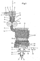
- the capillary threads made of synthetic polymers in particular polyamides such as PA 6 and PA 6.6 or polypropylene, which are spun in the spinning shaft and combined to form thread 1, are drawn off from a godet (not shown) and stretched between it and another godet in a known manner.
- the drawn thread 1 is then fed to a blow nozzle 2.
- the blowing nozzle has a supply line 4, which can be heated by electrical heating devices 3 or the like, for a propellant fluid, preferably air, water vapor or an inert gas.
- a propellant fluid preferably air, water vapor or an inert gas.
- the Driving fluid is distributed over the ring channel 5 and expanded via the conical annular gap 6, then hits the thread 1 in the thread channel 7 at high speed in order to plasticize it and drag it into the storage chamber 8, where the thread 1 is on the one already deposited Thread material strikes and is compressed into a compact thread plug 9.
- the propellant fluid can escape through openings 10 in the wall of the storage chamber 8.
- the diameter or cross section of the thread plug 9 corresponds to that of the storage chamber.
- the lower end of the storage chamber 8 is closed by the slide 11, so that the thread plug 9 can initially form.
- the stowage chamber 8 is then opened and the thread stopper is continuously conveyed at its growth rate and fed to the driven conveyor rollers 12.
- the conveyor rollers 12 have a semicircular or rectangular recess on the circumference and thus form the thread stopper 9 conveyed out of the storage chamber 8. They convey the thread stopper 9 to a treatment drum 13 which rotates slowly. Although they are not absolutely necessary, they are used in a preferred embodiment of the texturing device in order to achieve constant operating conditions as a result of the forced conveyance of the thread plug 9.
- the thread plug 9 is guided tangentially onto the treatment drum 13.
- a deflection plate 14 is optionally provided between the outlet gap of the conveyor rollers 12 and the treatment drum 13. Such a deflection can loosen the consistency of the thread plug 9, for example, and significantly increase its gas permeability.
- the thread stopper 9 which, for example, has a circular cross section due to the recess on the circumference of the conveyor rollers 12, is wound onto the rotatingly driven treatment drum 13.
- a feed device 15, which is arranged in a stationary manner and surrounds the treatment drum 13 in a helical manner on part of its circumference, forces the deposited thread stopper 9 to have a movement component in the axial direction of the treatment drum 13, so that the thread stopper in helical windings and in dense layers side by side over the treatment drum is moved.
- the treatment drum 13 has openings 16 distributed over its jacket, for example in the form of slots or perforations. For better illustration, some turns of the thread plug 9 are omitted in FIG. 1. It can also be seen from FIG. 1 that the treatment drum is mounted in the bearings 17 and is driven in the direction of rotation 20 via a pulley 18 with tangential belts 19. The speed of rotation of the treatment drum - adjusted to the growth speed of the thread plug 9 and the dissolution speed of the thread plug at the end of the drum - can be adjusted via a speed control drive (not shown) in such a way that the steady state of the dissolving point of the thread plug 9 remains approximately at the set point and on the Drum circumference does not move.
- a speed control drive not shown
- the drive axis of the treatment drum 13 is connected via a labyrinth 21 to the stationary suction nozzle 22 of a suction device known per se.
- a negative pressure is hereby generated in the hollow drum 13. Due to this negative pressure, ambient air is sucked through the layers of the thread plug turns 9.1 lying next to one another in a helical manner on the treatment drum 13, and these are sufficiently cooled so that the crimp generated in the storage chamber 8 is fixed before the thread plug 9 at the end of the drum is released and the textured thread is drawn off tangentially from the trigger device 23.
- the thread pulling aid 24 is now arranged, by means of which the last turn of the thread plug is separated from the other, closely spaced turns 9.1.
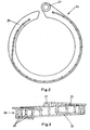
- the thread take-off aid 24 is designed as a sickle-like separating element which at least partially surrounds the circumference of the treatment drum 13 like a helical ring 25.
- the separating element is shown according to a preferred embodiment. It surrounds the treatment drum 13 over almost the entire drum circumference and has an open cage 26 which projects towards the end of the drum.
- Reference numeral 27 designates the bearing eye in which the separating element is axially displaceable and oscillating on an axis arranged parallel to and above the drum axis.
- the center of gravity of the separating element should lie in a vertical plane in which the drum axis also lies.
- the cage 26 consists of several, oriented parallel to the drum axis and the same long rods, for example, cylindrical pins 28 of equal length, which are arranged on two circular arc sections concentric to the drum axis with an intermediate transition region.
- the cage 26 is closed at its projecting end by a ring element 30 through which the free ends of the pins 28 are connected to one another. This prevents the thread from being caught in the pins when it is put on; the risk of injury for the operating personnel is also less great.
- the arrangement of the pins prevents chipped fragments of the thread plug 9 from being flung away from the drum surface at high speed. Rather, such bridges are caught and held or clamped between the drum surface and the cage bars until said fragment of the thread plug 9 is completely dissolved.
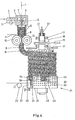
- a thread pulling aid 24 is shown, which essentially exerts pneumatic effects.
- the treatment drum 13 is again shown with thread plug turns wound thereon.
- a circular cylindrical pot (34) is placed over the thread take-off end of the treatment drum, the bottom surface 35 of which rests closely against the free end face 36 of the drum 13.
- the diameter of the pot essentially corresponds to the diameter of the drum with a closed thread plug turn resting on it.
- the pot has an axially directed thread outlet slot 37 through which the threads or the thread are drawn off by means of delivery mechanism 23 (take-off device).
- a first screen 31 adjoins the axial slot as part of the pot casing.
- a recess 48 This is followed by a recess 48 and this in turn is followed by a second, rear panel 33.
- a recess 48 Between the panels 31 and 33, i.e. - in the recess 48 is the desired opening point 32 of the thread plug.
- Both diaphragms extend socially essentially over the last thread plug turn (s).
- the rear edge 49 of the recess essentially forms the front edge of the last thread plug turn (s).
- the jacket has a perforation 46, the air permeability of which is, however, less than the air permeability of the treatment drum.
- the rear panel 33 extends to the thread outlet slot. It should be mentioned that the thread runs over more than 90 °, preferably also more than 180 °, from the point of dissolution until it is removed from the treatment drum over the drum surface.
- the aperture 31 and the aperture 33 cause a particularly high air flow in the recess 48, which is directed radially onto the surface of the cooling drum.
- air is also passed over the edge of the fume cup, i.e. the front edges of the diaphragms 31 and 33 and over the circumferential edge 49 of the recess 48 are drawn in the axis-parallel direction under the trigger cup. This gives the air flow a very strong axial component.
- the thread stopper in dissolution is pressed very strongly onto the drum surface and the thread stopper and the loosened thread are blown towards the free end of the treatment drum.
- the distance between the bottom surface 35 of the trigger cup and the end face of the cooling drum 36 and the size of the perforation 46 and the exial thread take-off slot 37 are chosen so that the radial and axial components of the air flow prevailing in the recess are sufficiently strong to reach the point of resolution (s) to fix the thread plug (s) in the area of the recess and to ensure a clean separation of the last thread plug thread (s) and in particular the loosened thread (threads) from the penultimate thread plug thread. on the other hand to avoid that the stripped thread stopper thread (s) and in particular the dissolved thread (s) are pulled over the end face 36 of the treatment drum 13, which would lead to a malfunction of the system.
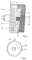
- FIG. 5 shows a modified exemplary embodiment.
- Two threads are treated here, which are wound on the treatment drum 13 to form two thread plug turns 39 and 40 lying side by side. These two thread plugs are released again in the area of the recess between the diaphragms 31 and 33 to form the threads 41, 42.
- the edge of the pot 34 i.e. the leading edge of the diaphragms 31 and 33 is adapted in its slope to the slope of the penultimate pair of thread plug turns and extends up to this penultimate pair of thread plug turns.
- the axial extent of the recess between the diaphragms 31 and 33 is in turn adapted to the sum of the diameters of the thread plugs 39, 40 to be treated, so that the front edge 49 of the recess 48 extends to the last thread plug turn. Because the front edge of the diaphragms 31, 33 is adapted to the slope of the penultimate thread plug turn, the action of the axially directed air flow component can be further improved.
- the pot 34 is mounted with a slide bearing 45 on the free shaft end of the treatment drum. The stopper is prevented from rotating by stop 50.
- the pot 34 is mounted eccentrically on the shaft with its slide bearing bush 45, so that the clear distance between the drum surface and the diaphragm 33 to the thread outlet slot 37 becomes ever narrower.
- the operation of the trigger pot is now as follows: The fact that the free end of the treatment drum 13 through the panels 31st and 33 is substantially covered, a strong axial air flow is drawn under the trigger cup 34 over the leading edges of the diaphragms 31 and 33, which preferably and substantially match the gradient of the penultimate pair of thread plug windings. Furthermore, a strong radial air flow arises in the area of the recess 48, which presses the thread plugs 39 and 40 to be released onto the drum surface.
- thread plugs running side by side are formed from the threads, as shown in FIG. 5 for two threads 41, 42 or two thread plugs 39, 40. If one speaks of a thread plug turn in the context of this application, this always means a number of thread plug turns running side by side, which corresponds to the number of threads running in parallel and treated together.
Landscapes
- Engineering & Computer Science (AREA)
- Mechanical Engineering (AREA)
- Textile Engineering (AREA)
- Yarns And Mechanical Finishing Of Yarns Or Ropes (AREA)
- Spinning Methods And Devices For Manufacturing Artificial Fibers (AREA)
Applications Claiming Priority (2)
| Application Number | Priority Date | Filing Date | Title |
|---|---|---|---|
| DE2809204 | 1978-03-03 | ||
| DE19782809204 DE2809204A1 (de) | 1978-03-03 | 1978-03-03 | Vorrichtung zum thermischen behandeln, insbesondere zum kuehlen mindestens eines kontinuierlich laufenden in staukammern gebildeten fadenstopfens |
Publications (2)
| Publication Number | Publication Date |
|---|---|
| EP0003952A1 EP0003952A1 (de) | 1979-09-19 |
| EP0003952B1 true EP0003952B1 (de) | 1981-09-16 |
Family
ID=6033485
Family Applications (1)
| Application Number | Title | Priority Date | Filing Date |
|---|---|---|---|
| EP78101745A Expired EP0003952B1 (de) | 1978-03-03 | 1978-12-18 | Verfahren und Vorrichtung zur thermischen Behandlung von Fäden |
Country Status (4)
| Country | Link |
|---|---|
| US (1) | US4301578A (enExample) |
| EP (1) | EP0003952B1 (enExample) |
| JP (1) | JPS54125749A (enExample) |
| DE (2) | DE2809204A1 (enExample) |
Cited By (1)
| Publication number | Priority date | Publication date | Assignee | Title |
|---|---|---|---|---|
| CN103243423A (zh) * | 2013-05-29 | 2013-08-14 | 济南大自然化学有限公司 | 纤维丝束与卷曲机自动对接装置 |
Families Citing this family (12)
| Publication number | Priority date | Publication date | Assignee | Title |
|---|---|---|---|---|
| US4620345A (en) * | 1983-05-19 | 1986-11-04 | Fleissner Gmbh & Company | Apparatus for crimping and setting synthetic fiber groups |
| US5974777A (en) * | 1998-04-21 | 1999-11-02 | Davis; David M | Yarn texturizer cooling drum |
| EP0982418B1 (de) * | 1998-08-27 | 2005-12-21 | Saurer GmbH & Co. KG | Vorrichtung und Verfahren zum Stauchkräuseln eines synthetischen Fadens |
| US6892702B2 (en) * | 2000-10-12 | 2005-05-17 | Kabushiki Kaisha Moric | Ignition controller |
| US7150083B2 (en) * | 2001-05-10 | 2006-12-19 | Saurer Gmbh & Co. Kg | Compressive crimping device for a synthetic multi-threaded yarn |
| DE10202788A1 (de) * | 2002-01-25 | 2003-07-31 | Rieter Ag Maschf | Texturieranlage und Texturierdüse hierfür |
| DE102005020884A1 (de) * | 2005-05-04 | 2006-11-09 | Dietze & Schell Maschinenfabrik Gmbh | Verfahren und Vorrichtung zur Herstellung von Kunstgras |
| US7386925B2 (en) * | 2006-10-04 | 2008-06-17 | Dietze & Schell Maschinenfabrik | Process and apparatus for the production of artificial grass |
| EP2084315B1 (de) | 2006-11-04 | 2014-01-08 | Oerlikon Textile GmbH & Co. KG | Verfahren und vorrichtung zum kräuseln eines multifilen fadens |
| DE102012004747A1 (de) * | 2012-03-08 | 2013-09-12 | Oerlikon Textile Gmbh & Co. Kg | Kräuselvorrichtung |
| US10072363B2 (en) * | 2015-07-13 | 2018-09-11 | Oerlikon Textile Gmbh & Co. Kg | Cooling drum for cooling a thread plug |
| BE1024740B1 (nl) * | 2016-11-22 | 2018-06-18 | Wiele Michel Van De Nv | Inrichting en werkwijze voor het vervaardigen van gekroesd textielgaren en koeltrommel voor een dergelijke inrichting |
Family Cites Families (7)
| Publication number | Priority date | Publication date | Assignee | Title |
|---|---|---|---|---|
| US2321757A (en) * | 1941-07-22 | 1943-06-15 | American Viscose Corp | Method and apparatus for crimping textile fibrous material |
| GB1085057A (en) * | 1963-07-29 | 1967-09-27 | Courtaulds Ltd | Yarn production |
| US3217482A (en) * | 1963-08-30 | 1965-11-16 | Monsanto Co | Apparatus for texturizing yarn |
| GB1082452A (en) * | 1963-09-26 | 1967-09-06 | Ici Ltd | Apparatus for heating filamentary material |
| BE653626A (enExample) * | 1963-09-26 | |||
| US3478401A (en) * | 1967-12-08 | 1969-11-18 | Deering Milliken Res Corp | Method and apparatus for treating textile yarn |
| US4118843A (en) * | 1976-07-16 | 1978-10-10 | Barmag Barmer Maschinenfabrik Aktiengesellschaft | Processes and apparatus for thermal treatment of filaments |
-
1978
- 1978-03-03 DE DE19782809204 patent/DE2809204A1/de not_active Withdrawn
- 1978-12-18 DE DE7878101745T patent/DE2861105D1/de not_active Expired
- 1978-12-18 EP EP78101745A patent/EP0003952B1/de not_active Expired
-
1979
- 1979-03-02 JP JP2351179A patent/JPS54125749A/ja active Granted
- 1979-03-05 US US06/017,251 patent/US4301578A/en not_active Expired - Lifetime
Cited By (1)
| Publication number | Priority date | Publication date | Assignee | Title |
|---|---|---|---|---|
| CN103243423A (zh) * | 2013-05-29 | 2013-08-14 | 济南大自然化学有限公司 | 纤维丝束与卷曲机自动对接装置 |
Also Published As
| Publication number | Publication date |
|---|---|
| JPS54125749A (en) | 1979-09-29 |
| US4301578A (en) | 1981-11-24 |
| JPS6214655B2 (enExample) | 1987-04-03 |
| DE2861105D1 (en) | 1981-12-03 |
| DE2809204A1 (de) | 1979-09-13 |
| EP0003952A1 (de) | 1979-09-19 |
Similar Documents
| Publication | Publication Date | Title |
|---|---|---|
| DE2943063C3 (de) | Offen-end-spinnvorrichtung | |
| EP0003952B1 (de) | Verfahren und Vorrichtung zur thermischen Behandlung von Fäden | |
| CH630123A5 (de) | Verfahren und vorrichtung zum friktionsspinnen von garn nach dem offen-end-prinzip. | |
| EP0310890B1 (de) | Verfahren und Vorrichtung zum kontinuierlichen Kräuseln von thermoplastischen Fäden | |
| CH642403A5 (de) | Spindelloses spinnverfahren und vorrichtung zur herstellung von garnen auf einer spinnmaschine. | |
| CH641215A5 (de) | Verfahren zum friktionsspinnen von garn nach dem offen-end-prinzip und vorrichtung zum durchfuehren dieses verfahrens. | |
| CH666061A5 (de) | Verfahren und vorrichtung zur spinnfasernformation. | |
| DE1510998C3 (de) | Offenend-Spinnvorrichtung | |
| CH655956A5 (de) | Verfahren und vorrichtung zum offenend-spinnen. | |
| CH679224A5 (enExample) | ||
| EP0230974B1 (de) | Fadenabzuggerät | |
| DE19610960A1 (de) | Verfahren zum Offenend-Spinnen | |
| WO2001079595A1 (de) | Verfahren und vorrichtung zur herstellung eines garnes mit ringgarnähnlichem charakter | |
| DE3330414A1 (de) | Verfahren und vorrichtung zum aufbereiten der einer friktionsspinnmaschine zugefuehrten spinnfasern | |
| EP1593762B1 (de) | Verfahren und Vorrichtung zum Stauchkräuseln eines multifilen Fadens | |
| DE2632082C2 (de) | Verfahren zur thermischen Nachbehandlung von gekräuselten thermoplastischen, multifilen Chemiefäden und Vorrichtung zum Durchführen des Verfahrens | |
| DE4225087A1 (de) | Offen-end-spinnvorrichtung des rotor-typs | |
| DE3025470C2 (de) | Offenend-Spinnvorrichtung | |
| DE2707084C2 (de) | Spinnverfahren und -vorrichtung | |
| DE3249876C2 (enExample) | ||
| DE4018702A1 (de) | Vorrichtung zum verspinnen von stapelfasern zu einem garn | |
| DE3402083C2 (de) | Verfahren und Vorrichtung zur Spinnfasernformation | |
| EP0222101B1 (de) | Verfahren zum Anspinnen eines Garnes an einer Friktionsspinnvorrichtung | |
| DE2633474B2 (de) | Vorrichtung zum Ablegen eines fadenförmigen Gutes bzw. eines Fadenkabels in einen Behälter o.dgl. endlos, oder in Form von Teilen begrenzter Länge | |
| DE4013689A1 (de) | Verfahren und vorrichtung zum verspinnen von stapelfasern zu einem garn |
Legal Events
| Date | Code | Title | Description |
|---|---|---|---|
| PUAI | Public reference made under article 153(3) epc to a published international application that has entered the european phase |
Free format text: ORIGINAL CODE: 0009012 |
|
| AK | Designated contracting states |
Designated state(s): BE CH DE FR GB IT NL |
|
| 17P | Request for examination filed | ||
| ITF | It: translation for a ep patent filed | ||
| GRAA | (expected) grant |
Free format text: ORIGINAL CODE: 0009210 |
|
| AK | Designated contracting states |
Designated state(s): BE CH DE FR GB IT NL |
|
| PG25 | Lapsed in a contracting state [announced via postgrant information from national office to epo] |
Ref country code: NL Effective date: 19810916 |
|
| REF | Corresponds to: |
Ref document number: 2861105 Country of ref document: DE Date of ref document: 19811203 |
|
| NLV1 | Nl: lapsed or annulled due to failure to fulfill the requirements of art. 29p and 29m of the patents act | ||
| PGFP | Annual fee paid to national office [announced via postgrant information from national office to epo] |
Ref country code: CH Payment date: 19841029 Year of fee payment: 7 |
|
| PGFP | Annual fee paid to national office [announced via postgrant information from national office to epo] |
Ref country code: FR Payment date: 19841030 Year of fee payment: 7 |
|
| PGFP | Annual fee paid to national office [announced via postgrant information from national office to epo] |
Ref country code: DE Payment date: 19841113 Year of fee payment: 7 |
|
| PGFP | Annual fee paid to national office [announced via postgrant information from national office to epo] |
Ref country code: BE Payment date: 19841231 Year of fee payment: 7 |
|
| PG25 | Lapsed in a contracting state [announced via postgrant information from national office to epo] |
Ref country code: BE Effective date: 19871231 |
|
| BERE | Be: lapsed |
Owner name: BARMAG BARMER MASCHINENFABRIK A.G. Effective date: 19871231 |
|
| GBPC | Gb: european patent ceased through non-payment of renewal fee | ||
| PG25 | Lapsed in a contracting state [announced via postgrant information from national office to epo] |
Ref country code: FR Free format text: LAPSE BECAUSE OF NON-PAYMENT OF DUE FEES Effective date: 19880831 |
|
| PG25 | Lapsed in a contracting state [announced via postgrant information from national office to epo] |
Ref country code: DE Effective date: 19880901 |
|
| REG | Reference to a national code |
Ref country code: FR Ref legal event code: ST |
|
| PG25 | Lapsed in a contracting state [announced via postgrant information from national office to epo] |
Ref country code: GB Free format text: LAPSE BECAUSE OF NON-PAYMENT OF DUE FEES Effective date: 19881117 |
|
| PG25 | Lapsed in a contracting state [announced via postgrant information from national office to epo] |
Ref country code: CH Effective date: 19881231 |
|
| REG | Reference to a national code |
Ref country code: CH Ref legal event code: PL |
|
| PLBE | No opposition filed within time limit |
Free format text: ORIGINAL CODE: 0009261 |
|
| STAA | Information on the status of an ep patent application or granted ep patent |
Free format text: STATUS: NO OPPOSITION FILED WITHIN TIME LIMIT |