EP0001367A1 - Erdbebensichere Gebäudekonstruktionen mit Untergeschossen, welche einen Schutz gegen Atomwaffen bilden - Google Patents
Erdbebensichere Gebäudekonstruktionen mit Untergeschossen, welche einen Schutz gegen Atomwaffen bilden Download PDFInfo
- Publication number
- EP0001367A1 EP0001367A1 EP78400106A EP78400106A EP0001367A1 EP 0001367 A1 EP0001367 A1 EP 0001367A1 EP 78400106 A EP78400106 A EP 78400106A EP 78400106 A EP78400106 A EP 78400106A EP 0001367 A1 EP0001367 A1 EP 0001367A1
- Authority
- EP
- European Patent Office
- Prior art keywords
- elements
- seismic
- construction according
- base
- seismic construction
- Prior art date
- Legal status (The legal status is an assumption and is not a legal conclusion. Google has not performed a legal analysis and makes no representation as to the accuracy of the status listed.)
- Granted
Links
Images

Classifications
-
- E—FIXED CONSTRUCTIONS
- E04—BUILDING
- E04H—BUILDINGS OR LIKE STRUCTURES FOR PARTICULAR PURPOSES; SWIMMING OR SPLASH BATHS OR POOLS; MASTS; FENCING; TENTS OR CANOPIES, IN GENERAL
- E04H9/00—Buildings, groups of buildings or shelters adapted to withstand or provide protection against abnormal external influences, e.g. war-like action, earthquake or extreme climate
- E04H9/04—Buildings, groups of buildings or shelters adapted to withstand or provide protection against abnormal external influences, e.g. war-like action, earthquake or extreme climate against air-raid or other war-like actions
- E04H9/06—Structures arranged in or forming part of buildings
- E04H9/08—Structures arranged underneath buildings, e.g. air-raid shelters
-
- E—FIXED CONSTRUCTIONS
- E04—BUILDING
- E04H—BUILDINGS OR LIKE STRUCTURES FOR PARTICULAR PURPOSES; SWIMMING OR SPLASH BATHS OR POOLS; MASTS; FENCING; TENTS OR CANOPIES, IN GENERAL
- E04H9/00—Buildings, groups of buildings or shelters adapted to withstand or provide protection against abnormal external influences, e.g. war-like action, earthquake or extreme climate
- E04H9/02—Buildings, groups of buildings or shelters adapted to withstand or provide protection against abnormal external influences, e.g. war-like action, earthquake or extreme climate withstanding earthquake or sinking of ground
- E04H9/028—Earthquake withstanding shelters
- E04H9/029—Earthquake withstanding shelters arranged inside of buildings
Definitions
- the present invention relates to the construction of buildings liable to be subjected to earthquakes of natural origin or caused by atomic explosions.
- the shelter must have a mechanical resistance far superior to conventional shelters in order to be able to resist in particular the seismic pressure wave, any cracking removing the seal necessary to cope with pollution and the dangers resulting from radioactive fallout. , gases and thermal effects and also water.
- the determining phenomenon for the collapse of the superstructures can be the atmospheric overpressure wave, or the seismic wave acting on the foundations which shakes the entire structure. In the case of an earthquake, it is the seismic wave that causes the buildings to shake and collapse.
- the aim of the present invention is to produce constructions in which the buried part can withstand intense seismic tremors, whether of natural or atomic origin, without risk of serious degradation, the horizontal displacements to which the buried part may be subjected. of construction, not being transmitted to the superstructure.
- the buried base of the construction is constituted by a plurality of independent elements having a mechanical resistance such that each of them is capable of withstanding without damage to the seismic wave of maximum intensity and to support a large fraction preferably greater than a third of the weight of the superstructure, the superstructure being calculated to resist in the case of an isostatic bearing on three points distributed randomly among its points of support provided for construction on the base elements, the shear strength of the connections to the support points of the super structure on the base elements being less than the overall shear strength of the elements of the structure leading to the point considered.
- the elements of the base can, under the effect of seismic waves, undergo relative displacements without any effort, in particular of shearing, greater than the mechanical resistance of the superstructure, being transmitted to the latter.
- a dislocation of the base into its independent elements can result in a support of the superstructure on only three of these elements providing isostatic support but without dislocation of the superstructure, which protects the occupants from the risk of collapse and allows a resumption in subsequent underpinning, for example by injection, to level the base again.
- the independent elements of the base are constituted, at least in part, by habitable cells forming atomic shelters.
- the independent elements are spaced from each other by a distance at least equal to the compressibility of a ground thickness equal and parallel to their greatest horizontal dimension under the maximum pressure developed by the seismic wave d 'maximum intensity.
- the gap between two independent elements is, in particular in the case of habitable cells, closed by a compressible material as impervious as possible to water, gases and radiation.
- This material distorted ble may be a heavy metal filled foam or a composite material based on foam and malleable metal layers.
- the elements of the base are separated from the elements of vertical walls delimiting the excavation of the base, the gap being filled with a tight compressible material.
- the emergency exit is carried out by tubular elements which can individually resist without crushing the earthquake of maximum intensity, the various elements being joined together by flexible joints capable of absorbing the relative displacements of two successive elements.
- the ends of two tubular elements successive, spaced apart by a sufficient distance to absorb the relative displacement are engaged in a tubular junction element having the same mechanical resistance characteristics but reserving between its internal surface and the external peripheral surface of the internal elements a clearance greater than the relative displacement, this clearance being filled with a deformable material similar to that used between the base elements.
- access to the emergency exit is closed off by a rigid destructible wall with the tools located in the shelter, for example a masonry wall, unreinforced concrete or other similar material.
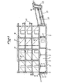
- the invention in the embodiment shown in the drawings, is applied to a two-story building.
- the buried basement is on one floor and has a part 1 forming garages and a part 2 forming an atomic shelter.
- Part 1 comprises a certain number of slabs 3, reinforced concrete slabs having a thickness and a sufficient reinforcement to be able to support each a significant fraction which can theoretically reach a third of the total weight of the construction, concentrated in their center. To increase their resistance, these slabs can be profiled and include beams forming a crossed network.
- the building is supported on the slabs 3 by posts 4 provided with a distribution sole 5.
- the distribution sole 5 is not secured to the slab 3, except possibly by irons of small section capable of being sheared in the event of a shear force exceeding the shear strength of the post 4.
- each support between the building and the base comprises, as shown in Figure 2, a cylinder 6 interposed with a ball joint system between each sole 5 and each post 4 or between a metal distribution sole 5 'bearing on a habitable cell 10 forming atomic shelter as described below and a support plate 7 incorporated in the system of load-bearing beams 8 of the building in superstructure.
- the jacks 6 are divided into three groups and the jacks of the same group are interconnected by pipes 9.
- Each jack or group of jacks can be connected to an enclosure for absorbing pressure waves in the form of a hydropneumatic chamber or analog not shown.
- a vertical wave which propagates under the elements with a vertical amplitude less than the stroke of the cylinders can be absorbed without damaging the construction.
- Part 2 is made up of habitable cells also made of reinforced concrete 10. These cells are calculated individually to be able, like the slabs 3, to support a large fraction of the weight of the construction and to be able to resist crushing by seismic waves acting on their lateral faces. It should be noted that when distributor actuator systems 6 are provided, the weight of the construction is always distributed between the various supports and the fraction of the weight of the building that each support must support is therefore lower. These cells are equipped, like all conventional atomic shelters, with standard emergency equipment with regard to means of survival, ventilation, lighting and disinfection. They can be used directly as support, without mechanical connection preventing a horizontal displacement or limiting it beyond a certain shearing force, to the superstructure construction. This support can also include a hydrostatic connection device as shown in FIG. 2.
- the base elements, slabs 3 and cells 10 are separated by a distance approximately equal to the maximum amplitude of the displacement which can receive the element under the effect of a natural or atomic earthquake.
- the gap thus created is filled by a seal 11 made of an elastically deformable waterproof material which can be a plastic foam loaded with heavy metal salts.
- This joint can, as shown in Figure 2, be delimited or subdivided by lead walls or the like 12 which can be folded and anchored in neighboring elements.
- the plastic foam of the joint which must have as high elongation and compression coefficients, is preferably cast on site and it is possible to provide cavities in the surfaces of the adjacent parts. anchor for the foam (not shown) so that, even when stretched, the foam continues to seal.
- the side walls of the cells 10 directed towards the ground can be doubled by walls 13 which are separated from it by a thickness of foam 14 treated like the foam of the joints 11
- the side walls 15 of the other basements are preferably mounted also floating with seals 11 at the base and at the top.
- the watertightness, gas and radiation tightness of the seals not incorporated in part 2 forming an atomic shelter, can be neglected and they may be simple overlapping seals liable to shear under the stresses resulting from 'an earthquake.
- the superstructure construction 16 is constituted as a self-supporting element, especially when the load is transferred directly, that is to say without connection of the type of jacks 6, to the elements 3 and 10 of the base.
- truss-forming reinforcements 17 are embedded in the partitioning walls made of sheet concrete arranged in two orthogonal orientations.
- Architectural elements such as thresholds 18, pediments 19, balconies 20 and others are calculated as belt elements and reinforced accordingly.
- beams such as 21 in which a part of the truss reinforcement is embedded can be arranged in a grid on the terrace.
- Those of cells 10 which are in the vicinity of the land may include emergency exits leading by a buried hose 22 to an outlet well 23 disposed at a distance from the building 16 substantially equal to its height to prevent its outlet from being blocked by the collapsed parts.
- this outlet is surrounded by a concrete ring 24 forming a barrier against runoff water.
- the hose 22 consists of elements such as centrifugal reinforced concrete pipes 25 capable of resisting the seismic wave.
- the connections between elements are constituted by foam rings 26 having thicknesses sufficient to absorb the relative displacements. These rings are held in place by metal hoops 27. Access to the hose 22 can be achieved by destruction, using the tools located in the shelter, of a thinned part 28 of the facing wall. -vis cell 10, the frames 29 also being interrupted to the right of this thinned part.
Applications Claiming Priority (2)
| Application Number | Priority Date | Filing Date | Title |
|---|---|---|---|
| FR7728622 | 1977-09-22 | ||
| FR7728622A FR2404087A1 (fr) | 1977-09-22 | 1977-09-22 | Constructions anti-sismiques notamment constructions avec sous-sols formant abris anti-atomiques |
Publications (2)
| Publication Number | Publication Date |
|---|---|
| EP0001367A1 true EP0001367A1 (de) | 1979-04-04 |
| EP0001367B1 EP0001367B1 (de) | 1981-01-07 |
Family
ID=9195666
Family Applications (1)
| Application Number | Title | Priority Date | Filing Date |
|---|---|---|---|
| EP78400106A Expired EP0001367B1 (de) | 1977-09-22 | 1978-09-21 | Erdbebensichere Gebäudekonstruktionen mit Untergeschossen, welche einen Schutz gegen Atomwaffen bilden |
Country Status (8)
| Country | Link |
|---|---|
| US (1) | US4250671A (de) |
| EP (1) | EP0001367B1 (de) |
| JP (1) | JPS5457338A (de) |
| CA (1) | CA1116644A (de) |
| DE (1) | DE2837172C2 (de) |
| ES (1) | ES473055A1 (de) |
| FR (1) | FR2404087A1 (de) |
| TR (1) | TR21057A (de) |
Cited By (2)
| Publication number | Priority date | Publication date | Assignee | Title |
|---|---|---|---|---|
| GB2182371A (en) * | 1985-11-02 | 1987-05-13 | Roger Smith Jones | Underground structures |
| US5048244A (en) * | 1990-06-07 | 1991-09-17 | Marcel M. Barbier, Inc. | Underground shock-resistant structure |
Families Citing this family (14)
| Publication number | Priority date | Publication date | Assignee | Title |
|---|---|---|---|---|
| JPS57147953U (de) * | 1980-09-22 | 1982-09-17 | ||
| JPS57193632A (en) * | 1981-05-22 | 1982-11-29 | Saburo Shibata | Multi-purpose building constructed in watery place |
| JPS59150843U (ja) * | 1983-03-29 | 1984-10-09 | 吉松 孝吉 | 地下室を有する建造物 |
| FR2688818B1 (fr) * | 1992-03-17 | 1994-06-24 | Bernard Thomann | Batiment antisismique. |
| US5537790A (en) * | 1994-02-09 | 1996-07-23 | Jackson; Roger L. | Seismic bridge |
| US6298612B1 (en) | 1995-09-05 | 2001-10-09 | James A. Adams | Wall strengthening component |
| US5706626A (en) | 1995-12-14 | 1998-01-13 | Mueller; Lee W. | Pre-assembled internal shear panel |
| CN1080801C (zh) * | 1996-10-07 | 2002-03-13 | 邓庚厚 | 一种由上往下建造建筑物的顶升式建筑法 |
| JP2944565B2 (ja) * | 1996-11-28 | 1999-09-06 | 普 山田 | 地下室構造体、その運搬方法およびその施工方法 |
| US8397454B2 (en) | 1997-11-21 | 2013-03-19 | Simpson Strong-Tie Company, Inc. | Building wall for resisting lateral forces |
| US6385920B1 (en) * | 2000-06-30 | 2002-05-14 | Roy T. Chandler | Modular storm shelter with emergency breakaway access chute |
| US20080016793A1 (en) * | 2004-04-19 | 2008-01-24 | Majlessi Kamran R | Web hole reinforcing for metal wall stubs |
| WO2010151539A1 (en) | 2009-06-22 | 2010-12-29 | Barnet Liberman | Modular building system for constructing multi-story buildings |
| JP6179077B2 (ja) * | 2012-07-31 | 2017-08-16 | 株式会社大林組 | 避難用構造物および避難用施設 |
Citations (6)
| Publication number | Priority date | Publication date | Assignee | Title |
|---|---|---|---|---|
| DE630356C (de) * | 1934-05-27 | 1936-05-26 | Karl Walter Dipl Ing | Ausbau von unterirdischen Luftschutzraeumen zur Sicherung gegen Sprengwirkungen von Fliegerbomben und gegen das Eindringen von Giftgasen |
| DE638110C (de) * | 1934-03-10 | 1936-11-09 | Karl Scherbaum | Bombenabweisende Schutzbedachung fuer Bauwerke usw. |
| FR816490A (fr) * | 1936-04-15 | 1937-08-09 | Abri pour la protection des populations civiles | |
| FR1157413A (fr) * | 1956-08-16 | 1958-05-29 | Abri préfabriqué | |
| US3172377A (en) * | 1961-04-06 | 1965-03-09 | John A Dewar | Bomb shelter building |
| FR1486137A (fr) * | 1966-07-07 | 1967-06-23 | Dispositif ou abri de protection contre l'action des armes nucléaires |
Family Cites Families (14)
| Publication number | Priority date | Publication date | Assignee | Title |
|---|---|---|---|---|
| US981884A (en) * | 1909-03-11 | 1911-01-17 | Otto Ruhl | Earthquake-proof building. |
| DE375822C (de) * | 1921-01-20 | 1923-05-18 | Emil Diepenbrock | Sicherung von Gebaeuden gegen Bergschaeden |
| GB496592A (en) * | 1937-03-13 | 1938-12-02 | Willy Schramm | Improvements in buildings for rendering the same less liable to damage by air attack |
| US2271079A (en) * | 1937-06-16 | 1942-01-27 | Kieser Karl | Structural element |
| GB520326A (en) * | 1938-10-13 | 1940-04-19 | William Herbert Smith | Improvements relating to shelters |
| US2358143A (en) * | 1942-06-11 | 1944-09-12 | Fuller Label & Box Company | Vented panel |
| DE1108890B (de) * | 1956-03-16 | 1961-06-15 | Maschf Augsburg Nuernberg Ag | Gelenk fuer Bauwerke in Erdbeben- oder Bergschadensgebieten |
| US3099110A (en) * | 1957-09-17 | 1963-07-30 | Dur O Wal National Inc | Control joint |
| CH454429A (de) * | 1965-07-08 | 1968-04-15 | Staeheli Fritz | Unterirdischer Raum zum Schutz vor nuklearer Waffenwirkung |
| DE1264737B (de) * | 1966-06-21 | 1968-03-28 | Gustav Luding | Schutzbauanlage |
| CH499711A (de) * | 1969-02-15 | 1970-11-30 | Luding Gustav | Ein- und Ausgangstunnel für Schutzbauanlagen |
| US3908323A (en) * | 1974-07-11 | 1975-09-30 | Robert K Stout | Void creating device to be embedded in a concrete structure |
| US4102097A (en) * | 1974-12-23 | 1978-07-25 | Elemer Zalotay | Construction for supporting space units installed in a building especially a multi-storey building |
| DE2557043A1 (de) * | 1975-12-18 | 1978-09-14 | Peter Valerius | Gebaeude in raumzellenweise |
-
1977
- 1977-09-22 FR FR7728622A patent/FR2404087A1/fr active Granted
-
1978
- 1978-08-25 DE DE2837172A patent/DE2837172C2/de not_active Expired
- 1978-09-02 ES ES473055A patent/ES473055A1/es not_active Expired
- 1978-09-14 TR TR21057A patent/TR21057A/xx unknown
- 1978-09-21 EP EP78400106A patent/EP0001367B1/de not_active Expired
- 1978-09-22 CA CA000311912A patent/CA1116644A/fr not_active Expired
- 1978-09-22 JP JP11739878A patent/JPS5457338A/ja active Granted
- 1978-09-22 US US05/944,739 patent/US4250671A/en not_active Expired - Lifetime
Patent Citations (6)
| Publication number | Priority date | Publication date | Assignee | Title |
|---|---|---|---|---|
| DE638110C (de) * | 1934-03-10 | 1936-11-09 | Karl Scherbaum | Bombenabweisende Schutzbedachung fuer Bauwerke usw. |
| DE630356C (de) * | 1934-05-27 | 1936-05-26 | Karl Walter Dipl Ing | Ausbau von unterirdischen Luftschutzraeumen zur Sicherung gegen Sprengwirkungen von Fliegerbomben und gegen das Eindringen von Giftgasen |
| FR816490A (fr) * | 1936-04-15 | 1937-08-09 | Abri pour la protection des populations civiles | |
| FR1157413A (fr) * | 1956-08-16 | 1958-05-29 | Abri préfabriqué | |
| US3172377A (en) * | 1961-04-06 | 1965-03-09 | John A Dewar | Bomb shelter building |
| FR1486137A (fr) * | 1966-07-07 | 1967-06-23 | Dispositif ou abri de protection contre l'action des armes nucléaires |
Cited By (3)
| Publication number | Priority date | Publication date | Assignee | Title |
|---|---|---|---|---|
| GB2182371A (en) * | 1985-11-02 | 1987-05-13 | Roger Smith Jones | Underground structures |
| GB2182371B (en) * | 1985-11-02 | 1989-10-04 | Roger Smith Jones | Underground structures |
| US5048244A (en) * | 1990-06-07 | 1991-09-17 | Marcel M. Barbier, Inc. | Underground shock-resistant structure |
Also Published As
| Publication number | Publication date |
|---|---|
| CA1116644A (fr) | 1982-01-19 |
| FR2404087B1 (de) | 1982-04-30 |
| DE2837172A1 (de) | 1979-04-05 |
| US4250671A (en) | 1981-02-17 |
| DE2837172C2 (de) | 1984-08-23 |
| ES473055A1 (es) | 1979-04-01 |
| JPS5457338A (en) | 1979-05-09 |
| TR21057A (tr) | 1983-06-10 |
| EP0001367B1 (de) | 1981-01-07 |
| JPS6154905B2 (de) | 1986-11-25 |
| FR2404087A1 (fr) | 1979-04-20 |
Similar Documents
| Publication | Publication Date | Title |
|---|---|---|
| EP0001367B1 (de) | Erdbebensichere Gebäudekonstruktionen mit Untergeschossen, welche einen Schutz gegen Atomwaffen bilden | |
| KR101277967B1 (ko) | 지하 쉘터 | |
| EP0787865B1 (de) | Kasten und System zur Wärmedämmung und Bodendränage | |
| US9279265B1 (en) | Temporary shelter system | |
| US20070189854A1 (en) | Apparatus and method for flood defence | |
| US20110226166A1 (en) | Overhead protection system | |
| KR101921099B1 (ko) | 내진용 파일보강 구조 및 그 시공방법 | |
| US20150315805A1 (en) | Seismic isolation system | |
| RU2721552C1 (ru) | Полевое сборно-разборное фортификационное сооружение | |
| WO2002050377A1 (es) | Sistema constructivo de cimentaciones con placas antisismicas | |
| JP2007056600A (ja) | 逸震型地下室構造体とその構築工法 | |
| EP3666987A1 (de) | Vakuumhülle für selbststehendes, selbstisslierendes, schwimmendes, erdbebensicheres, und halbmobiles, gebäude | |
| AU2011200386B2 (en) | Disaster Protection Shelter | |
| FR2852620A1 (fr) | Dispositif de refuge parasismique | |
| RU2112835C1 (ru) | Устройство для гашения упругих волн при землетрясении | |
| RU2751172C1 (ru) | Полевое сборно-разборное модульное фортификационное сооружение | |
| FR2604462A1 (fr) | Edifice d'habitation destine a une seule famille | |
| JP3238390U (ja) | シェルター | |
| Boas | Archaeological evidence for the Mamluk sieges and dismantling of Montfort: a preliminary discussion | |
| Mallawaarachchi et al. | The effects of cyclones, tsunami and earthquakes on built environments and strategies for reduced damage | |
| JP3878375B2 (ja) | 建物 | |
| RU2065522C1 (ru) | Здание | |
| JP3358799B2 (ja) | 建築物 | |
| Jagadeesan | Upstream Waterproof Treatment with Protective Geomembrane for Masonry Dams-A Case Study on Upper Bhavani Dam, Tamil Nadu | |
| UA151558U (uk) | Модульне захисне сховище |
Legal Events
| Date | Code | Title | Description |
|---|---|---|---|
| PUAI | Public reference made under article 153(3) epc to a published international application that has entered the european phase |
Free format text: ORIGINAL CODE: 0009012 |
|
| AK | Designated contracting states |
Designated state(s): BE CH GB LU NL SE |
|
| 17P | Request for examination filed | ||
| D17P | Request for examination filed (deleted) | ||
| R17P | Request for examination filed (corrected) | ||
| R17P | Request for examination filed (corrected) | ||
| GRAA | (expected) grant |
Free format text: ORIGINAL CODE: 0009210 |
|
| AK | Designated contracting states |
Designated state(s): BE CH GB LU NL SE |
|
| PGFP | Annual fee paid to national office [announced via postgrant information from national office to epo] |
Ref country code: BE Payment date: 19930730 Year of fee payment: 16 |
|
| PGFP | Annual fee paid to national office [announced via postgrant information from national office to epo] |
Ref country code: LU Payment date: 19930819 Year of fee payment: 16 |
|
| PGFP | Annual fee paid to national office [announced via postgrant information from national office to epo] |
Ref country code: CH Payment date: 19930820 Year of fee payment: 16 |
|
| PGFP | Annual fee paid to national office [announced via postgrant information from national office to epo] |
Ref country code: GB Payment date: 19930913 Year of fee payment: 16 |
|
| PGFP | Annual fee paid to national office [announced via postgrant information from national office to epo] |
Ref country code: SE Payment date: 19930916 Year of fee payment: 16 |
|
| PGFP | Annual fee paid to national office [announced via postgrant information from national office to epo] |
Ref country code: NL Payment date: 19930930 Year of fee payment: 16 |
|
| EPTA | Lu: last paid annual fee | ||
| PG25 | Lapsed in a contracting state [announced via postgrant information from national office to epo] |
Ref country code: LU Free format text: LAPSE BECAUSE OF NON-PAYMENT OF DUE FEES Effective date: 19940921 Ref country code: GB Effective date: 19940921 |
|
| PG25 | Lapsed in a contracting state [announced via postgrant information from national office to epo] |
Ref country code: SE Effective date: 19940922 |
|
| PG25 | Lapsed in a contracting state [announced via postgrant information from national office to epo] |
Ref country code: CH Effective date: 19940930 Ref country code: BE Effective date: 19940930 |
|
| EAL | Se: european patent in force in sweden |
Ref document number: 78400106.7 |
|
| BERE | Be: lapsed |
Owner name: SACHET JEAN-MARIE Effective date: 19940930 Owner name: DI CRESCENZO CLAUDE Effective date: 19940930 Owner name: HIRSCH JEAN-RAPHAEL Effective date: 19940930 |
|
| PG25 | Lapsed in a contracting state [announced via postgrant information from national office to epo] |
Ref country code: NL Effective date: 19950401 |
|
| NLV4 | Nl: lapsed or anulled due to non-payment of the annual fee | ||
| GBPC | Gb: european patent ceased through non-payment of renewal fee |
Effective date: 19940921 |
|
| REG | Reference to a national code |
Ref country code: CH Ref legal event code: PL |
|
| EUG | Se: european patent has lapsed |
Ref document number: 78400106.7 |
|
| PLBE | No opposition filed within time limit |
Free format text: ORIGINAL CODE: 0009261 |
|
| STAA | Information on the status of an ep patent application or granted ep patent |
Free format text: STATUS: NO OPPOSITION FILED WITHIN TIME LIMIT |