EP0001080B1 - Unter Druck kuppelbare Verbindungskupplung - Google Patents
Unter Druck kuppelbare Verbindungskupplung Download PDFInfo
- Publication number
- EP0001080B1 EP0001080B1 EP78100763A EP78100763A EP0001080B1 EP 0001080 B1 EP0001080 B1 EP 0001080B1 EP 78100763 A EP78100763 A EP 78100763A EP 78100763 A EP78100763 A EP 78100763A EP 0001080 B1 EP0001080 B1 EP 0001080B1
- Authority
- EP
- European Patent Office
- Prior art keywords
- valve
- pressure
- acted
- coupling half
- coupling
- Prior art date
- Legal status (The legal status is an assumption and is not a legal conclusion. Google has not performed a legal analysis and makes no representation as to the accuracy of the status listed.)
- Expired
Links
- 238000010168 coupling process Methods 0.000 claims description 51
- 230000008878 coupling Effects 0.000 claims description 48
- 238000005859 coupling reaction Methods 0.000 claims description 48
- 238000000034 method Methods 0.000 claims 1
- 239000012530 fluid Substances 0.000 description 4
- 230000000694 effects Effects 0.000 description 3
- 230000006978 adaptation Effects 0.000 description 2
- 230000007704 transition Effects 0.000 description 1
Images
Classifications
-
- F—MECHANICAL ENGINEERING; LIGHTING; HEATING; WEAPONS; BLASTING
- F16—ENGINEERING ELEMENTS AND UNITS; GENERAL MEASURES FOR PRODUCING AND MAINTAINING EFFECTIVE FUNCTIONING OF MACHINES OR INSTALLATIONS; THERMAL INSULATION IN GENERAL
- F16L—PIPES; JOINTS OR FITTINGS FOR PIPES; SUPPORTS FOR PIPES, CABLES OR PROTECTIVE TUBING; MEANS FOR THERMAL INSULATION IN GENERAL
- F16L37/00—Couplings of the quick-acting type
- F16L37/28—Couplings of the quick-acting type with fluid cut-off means
- F16L37/30—Couplings of the quick-acting type with fluid cut-off means with fluid cut-off means in each of two pipe-end fittings
- F16L37/32—Couplings of the quick-acting type with fluid cut-off means with fluid cut-off means in each of two pipe-end fittings at least one of two lift valves being opened automatically when the coupling is applied
-
- Y—GENERAL TAGGING OF NEW TECHNOLOGICAL DEVELOPMENTS; GENERAL TAGGING OF CROSS-SECTIONAL TECHNOLOGIES SPANNING OVER SEVERAL SECTIONS OF THE IPC; TECHNICAL SUBJECTS COVERED BY FORMER USPC CROSS-REFERENCE ART COLLECTIONS [XRACs] AND DIGESTS
- Y10—TECHNICAL SUBJECTS COVERED BY FORMER USPC
- Y10T—TECHNICAL SUBJECTS COVERED BY FORMER US CLASSIFICATION
- Y10T137/00—Fluid handling
- Y10T137/8593—Systems
- Y10T137/87917—Flow path with serial valves and/or closures
- Y10T137/87925—Separable flow path section, valve or closure in each
- Y10T137/87965—Valve- or closure-operated by coupling motion
Definitions
- the invention relates to a pressure-connectable coupling coupling for hydraulic lines with the housing of a temporarily non-pressure-loaded and the housing of a coupling half that is constantly under pressure during operation, wherein a valve guide is mounted centrally in each housing, in each of which a spring-loaded, hydraulically actuatable valve is arranged axially displaceably is such that the valve heads are pressed together during the coupling process and the non-pressurized valve is shifted by twice the possible valve lift of the pressurized valve, and that the non-pressurized valve is loaded with a spring that is stronger than the pressurized valve, so that the pressure is constantly equalized pressurized.
- Valve is pressed into the open position against a stop provided in the constantly pressurized coupling half, resulting in a maximum valve passage cross-section for both valves.
- Coupling couplings of this type work in normal operation, that is to say, with the hydraulic fluid flowing in the same direction from the temporarily non-pressurized to the pressurized coupling half, performing completely satisfactorily.
- the valve that is constantly under pressure can strike, since the valve opposite is not fixed in its position.
- Such connection couplings are not to be used regularly if the direction of flow of the hydraulic fluid reverses operationally, possibly even suddenly, and the valve is also slammed shut. This is the case, for example, if double-acting cylinders are provided in hydraulic systems in which the pressure line and return line are identical.
- An increase in the pressure normally prevailing in such hydraulic systems can also be brought about by the fact that the weight of a consumer-side device rests on the corresponding piston, as is the case, for example, when lowering a fully loaded front loader.
- connection coupling in which the free path of the valve, which is temporarily not pressurized after coupling, can be restricted, so that it is no longer possible for the valves to recede.
- this adaptation of the coupling is perceived as being quite disadvantageous because it can only be carried out with a tool and is therefore often not carried out, or because it is forgotten because the described disadvantage only becomes apparent during operation.
- the object of the invention is to provide a connection coupling of the type described such that an unintentional slamming of the valve, which is constantly under pressure, even with sudden changes in the direction of flow of the hydraulic fluid, as well as with strong and abrupt pressure fluctuations in the hydraulic system, with certainty, even without subsequent adaptation of the coupling , is avoided.
- This is achieved according to the invention in that the diameter of the recess of the interior of the housing of the coupling half, which is temporarily not pressurized, and thus the free passage cross-section around the valve guide or valve stem is larger than that in the constantly pressurized coupling half.
- the valves are in the normal flow direction of the hydraulic fluid from the coupling half, which is sometimes not under pressure, to the coupling half, which is constantly under pressure, on the one hand by the stronger spring pressure of the valve in the coupling half, which is not pressurized at the time, but on the other hand by hydraulic forces are pressed on the stop in the constantly pressurized coupling half and thus kept perfectly open in a known manner.
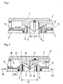
- Valve guides 14, 15 are provided in the housing 1 of a coupling sleeve that is temporarily not pressurized, as well as in the housing 2 of a coupling plug that is constantly pressurized during operation, in which valves 5, 6 are arranged axially displaceably.
- the valves 5, 6 are pressed onto their associated valve seat by springs 3, 4.
- the spring 3 of the valve 5 in the coupling half which is temporarily not pressurized, the coupling sleeve, is formed stronger than the spring 4 in the opposite coupling half.
- valve 6 of the coupling plug being pressed by the powerful spring 3 of the valve 5 of the coupling sleeve against a stop 9 formed by the valve guide 15.
- the valve 6 cannot be moved axially, with the result that the valve 5 is displaced into the coupling sleeve by the path S1 + S 2 . Only when the pressure is equalized can the stronger spring 3 of the valve 5 then have an effect and also move the valve 6 into the open position shown in FIG. 2 against the stop 9 of the valve guide 15.
- the connecting coupling is constructed in such a way that the free passage cross section in the space 18 around the valve guide 14 of the coupling sleeve is larger than that of the space 17 around the valve guide 15 of the coupling plug and that this in turn is larger than the valve passage cross section 13 the volumes of the rooms 18, 17 and the space around the valves 5, 6.
- the valves 5, 6 are designed together with their valve seats 10, 11 so that the valve passage cross section 13 over the entire distance 19, despite the increasing diameter of the Valves 5, 6 remain the same.
- the valve 5 is sharply offset on the side 12 facing the space 18 around the valve guide 14 in the coupling sleeve in order to achieve a sudden transition from the valve passage cross section 13 to the space 18 around the valve guide 14 of the coupling sleeve.
- valve 6 When the hydraulic medium flows in the direction of the arrow 16, the valve 6 is pressed against the stop of the valve guide 15 both by the pressure of the spring 3 and by the pressure of the flowing medium, so that both valves 5, 6 are securely located in FIG 2 open position shown remain. However, even when the direction of the flow is reversed in the direction of arrow 20, this position is maintained since, due to the enlargement of the cross section in space 18, hydraulic pressure builds up, which in turn tends to move valves 5, 6 in the direction of stop 9 . Since the valve passage cross section 13 due to the special shape of the valves 5, 6 and their valve seats 10, 11 on the. entire distance 19 remains the same, there are no pressure changes here or no forces possibly displacing the valves 5, 6 act on these valves 5, 6.
Landscapes
- Engineering & Computer Science (AREA)
- General Engineering & Computer Science (AREA)
- Mechanical Engineering (AREA)
- Check Valves (AREA)
- Safety Valves (AREA)
- Adhesive Tapes (AREA)
- Quick-Acting Or Multi-Walled Pipe Joints (AREA)
- Hydraulic Clutches, Magnetic Clutches, Fluid Clutches, And Fluid Joints (AREA)
Description
- Die Erfindung betrifft eine unter Druck kuppelbare Verbindungskupplung für Hydraulikleitungen mit dem Gehäuse einer zeitweise nicht druckbelasteten und dem Gehäuse einer im Betrieb ständig under Druck stehenden Kupplungshälfte, wobei zentrisch in jedem Gehäuse eine Ventilführung angebracht ist in der je ein federbelastetes, hydraulisch beaufschlagbares Ventil axial verschiebbar angeordnet ist derart, daß die Ventilköpfe beim Kupplungsvorgang aufeinandergedrückt werden und hierbei das nicht durckbeaufschlagte Ventil um den doppelten möglichen Ventilhub des druckbeaufschlagten Ventils verschoben wird, und daß das nicht druckbeaufschlagte Ventil mit einer gegenüber dem druckbeaufschlagten Ventil stärkeren Feder belastet ist, so daß beim Druckausgleich das ständig druckbeaufschlagte. Ventil in die Offenstellung gegen einen in der ständig druckbeaufschlagten Kupplungshälfte vorgesehenen Anschlag gedrückt wird wobei sich ein maximaler Ventil-Durchgangsquerschnitt bei beiden Ventilen ergibt.
- Verbindungskupplungen dieser Art arbeiten im Normalbetrieb, also bei stets in gleicher Richtung von der zeitweise nicht druckbelasteten zur druckbelasteten Kupplungshälfte strömenden Hydraulikflüssigkeit vollkommen zufriedenstellend. Schon dann jedoch, wenn starke Druckschwankungen und Druckstöße auftreten, die eine Umkehrung der Strömungsrichtung hervorrufen können, kann das ständig unter Druck stehende Ventil zuschlagen, da das gegenüberliegende Ventil in seiner Lage nicht fixiert ist. Regelmäßig sind derartige Verbindungskupplungen dann nicht zu gebrauchen, wenn sich die Strömungsrichtung der Hydraulikflüssigkeit betriebsmäßig, unter Umständen sogar noch schlagartig, umkehrt und damit auch das Ventil zugeschlagen wird. Dies ist beispielsweise dann der Fall, wenn doppelt wirkende Zylinder in hydraulischen Anlagen vorgesehen sind, bei denen Druckleitung und Rücklaufleitung identisch sind. Eine Verstärkung des normalerweise in derartigen Hydraulikanlagen herrschenden Druckes kann zudem noch dadurch hervorgerufen werden, daß das Gewicht eines verbraucherseitigen Gerätes auf dem entsprechenden Kolben lastet, wie dies beispielsweise beim Absenken eines vollbelasteten Frontladers der Fall ist.
- Zum Stand der Technik gehört eine Verbindungskupplung, bei der der freie Weg des zeitweise nicht druckbeaufschlagten Ventils nach dem Kuppeln eingeschränkt werden kann, so daß ein Zurückweichen der Ventile nicht mehr möglich ist. Diese Anpassung der Kupplung wird jedoch als recht nachteilig empfunden, da sie zum einen nur mit Werkzeug auszuführen ist und daher öfters nicht veorgenommen wird, oder weil sie, da sich der beschriebene Nachteil erst im Betrieb bemerkbar macht, vergessen wird.
- Aufgabe der Erfindung ist es, eine Verbindungskupplung der beschriebenen Art so auszubilden, daß ein unbeabsichtigtes Zuschlagen des ständig unter Druch stehenden Ventils auch bei schlagartigen Änderungen der Strömungsrichtung der Hydraulikflüssigkeit wie auch bei starken und abrupten Druckschwankungen im Hydrauliksystem mit Sicherheit, auch ohne nachträgliche Anpassung der Kupplung, vermieden wird. Erreicht wird dies nach der Erfindung dadurch, daß der Durchmesser der Ausdrehung des Innenraumes des Gehäuses der zeitweise nicht druckbeaufschlagten Kupplungshälfte und damit der freie Druchgangsquerschnitt um die Ventilführung bzw. den Ventilschaft dentlich größer ist als derjenige in der ständig druckbeaufschlagten Kupplungshälfte.
- Bei einer derartigen Ausbildung der Verbindungskupplung werden bei der Normal-Strömungsrichtung der Hydraulikflüssigkeit von der zeitweise nicht unter Druck stehenden Kupplungshälfte zu der ständig unter Druck stehenden Kupplungshälfte die Ventile einmal durch den stärkeren Federdruck des Ventils in der zeitweise nicht druckbeaufschlagten Kupplungshälfte, zum anderen aber auch durch hydraulische Kräfte auf den Anschlag in der ständig druckbeaufschlagten Kupplungshälfte gedrückt und damit inbekannter Weise einwandfrie offen gehalten. Diese Offenhaltung der Ventile stellt sich durch die erfindungsgemässe Ausbildung aber auch bei einer Umkehr der Strömungsrichtung ein, da sich nach den Strömungsgesetzen in dem deutlich größeren Durchgangsquerschnitt um die Ventilführung bzw, den Ventilschaft der zeitweise nicht unter Druck stehenden Kupplungshälfte, der sich durch die größere Ausdrehung beziehungsweise durch den größeren Innenraum ergibt, relativ zu dem engen Ventildurchgangsquerschnitt ein solch hoher Druck aufbaut, daß zusammen mit der das Ventil in der zeitweise nicht druckbeaufschlagten Kupplungshälfte belasteten starken Feder mit Sicherheit ein Zuschlagen des Ventils in der ständig druckbeaufschlagten Kupplungshälfte Verhindert wird. Diese Wirkung kann noch dadurch unterstützt werden, daß der Ventil-Durchgangsquerschnitt über beide Ventilköpfe hinweg gleichbleibend ist, so daß über diese Wegstrecke keine Druckänderung stattfindet.
- Vorteilhaft ist schließlich auch noch, daß der Durchmesser der Ausdrehung des Innenraumes bis zum in Arbeitslage befindlichen Ventilkopf gleichbleibt und dort sprunghaft übergeht in den deutlich kleineren Aussendurchmesser des Ventil-Durchgangsquerschnittes. Durch diese Maßnahme stellt sich nicht nur der gewünschte Effekt des Druckaufbaues eindeutig ein, sondern es wird auch der Durchgangswiderstand der Verbindungskupplung verkleinert.
- Auf der Zeichnung sind Ausführungsbeispiele des Erfindungsgegenstandes schematisch dargestellt und zwar zeigen:
- Fig. 1 die Verbindungskupplung vor dem Kuppelvorgang,
- Fig. 2 die gekuppelte Verbindungskupplung nach erfolgtem Druckausgleich,
- Fig. 4 eine Ventilausführung mit Ringkolben und.
- Im Gehäuse 1 einer zeitweise nicht druckbeaufschlagten Kupplungsmuffe wie auch im Gehäuse 2 eines im Betrieb ständig druckbeaufschlagten Kupplungssteckers sind Ventilführungen 14, 15, vorgesehen in denen Ventile 5, 6 axial verschiebbar angeordnet sind. Die Ventile 5, 6 werden durch Federn 3, 4 auf ihren zugehörigen Ventilsitz aufgepresst. Die Feder 3 des Ventiles 5 in der zeitweise nicht druckbeaufschlagten Kupplungshälfte, der Kupplungsmuffe, ist hierbei stärker ausgebildet als die Feder 4 in der gegenüberliegenden Kupplungshälfte. Beim Kuppeln der drucklosen Kupplungshälften stoßen die Ventilköpfe 7, 8 aufeinander und verschieben sich während des Kuppelvorganges jeweils um den Ventilhub sl. Hierdurch ergibt sich die Offenstellung nach Fig. 2, wobei das Ventil 6 des Kupplungssteckers durch die kräftige Feder 3 des Ventils 5 der Kupplungsmuffe gegen einen, durch die Ventilführung 15 gebildeten Anschlag 9 gedrückt wird. Steht der Kupplungsstecker jedoch unter Druck, so läßt sich das Ventil 6 nicht axial verschieben, womit das Ventil 5 um den Weg Sl+S2 in die Kupplungsmuffe hineinverschoben wird. Erst bei Druckausgleich kann sich dann die stärkere Feder 3 des Ventiles 5 auswirken und auch das Ventil 6 in die in Fig. 2 gezeigte Offenstellung gegen den Anschlag 9 der Ventilführung 15 verschieben. Konstruktiv ist die Verbindungskupplung so aufgebaut, daß der freie Durchtrittsquerschnitt im Raum 18 um die Ventilführung 14 der Kupplungsmuffe größer ist als derjenige des Raumes 17 um die Ventilführung 15 des Kupplungssteckers und daß dieser wiederum größer ist als der Ventil-Durchgangsquerschnitt 13. Entsprechend verhalten sich auch die Volumina der Räume 18, 17 sowie des Raumes um die Ventile 5, 6. Die Ventile 5, 6 sind zusammen mit ihren Ventilsitzen 10, 11 so ausgelegt, daß der Ventil-Durchgangsquerschnitt 13 über die gesamte Wegstrecke 19, trotz des ansteigenden Durchmessers der Ventile 5, 6 gleich bleibt. Das Ventil 5 ist an der dem Raum 18 um die Ventilführung 14 in der Kupplungsmuffe zugewandten Seite 12 scharfkantig abgesetzt, um einen sprunghalften Übergang von dem Ventil-Durchgangsquerschnitt 13 zu dem Raum 18 um die Ventilführung 14 der Kupplungsmuffe zu erreichen.
- Bei einer Strömung des hydraulischen Mediums in Richtung des Pfeiles 16 wird das Ventil 6 sowohl durch den Druck der Feder 3 wie auch durch den Druck des strömenden Mediums gegen den Anschlag der Ventilführung 15 gedrückt, womit beide Ventile 5, 6 sicher in'der in Fig. 2 gezeigten offenen Lage verbleiben. Jedoch auch bei einer Richtungsumkehr der Strömung in Richtung des Pfeiles 20, wird diese Lage beibehalten, da sich dann, durch die Querschnittsvergrößerung im Raum 18, ein hydraulischer Druck aufbaut der wiederum bestrebt ist die Ventile 5, 6 in Richtung auf den Anschlag 9 zu verschieben. Da der Ventil-Durchgangsquerschnitt 13 durch die besondere Form der Ventile 5, 6 und deren Ventilsitze 10, 11 über die. gesamte Wegstrecke 19 gleich bleibt, finden hier keine Druckänderungen statt beziehungsweise wirken keine die Ventile 5, 6 möglicherweise axial verschiebenden Kräfte auf diese Ventile 5, 6 ein.
Claims (3)
Applications Claiming Priority (2)
| Application Number | Priority Date | Filing Date | Title |
|---|---|---|---|
| DE2741027 | 1977-09-12 | ||
| DE19772741027 DE2741027A1 (de) | 1977-09-12 | 1977-09-12 | Unter druck kuppelbare verbindungskupplung |
Publications (2)
| Publication Number | Publication Date |
|---|---|
| EP0001080A1 EP0001080A1 (de) | 1979-03-21 |
| EP0001080B1 true EP0001080B1 (de) | 1983-04-27 |
Family
ID=6018750
Family Applications (1)
| Application Number | Title | Priority Date | Filing Date |
|---|---|---|---|
| EP78100763A Expired EP0001080B1 (de) | 1977-09-12 | 1978-08-28 | Unter Druck kuppelbare Verbindungskupplung |
Country Status (10)
| Country | Link |
|---|---|
| US (1) | US4274441A (de) |
| EP (1) | EP0001080B1 (de) |
| AT (1) | AT367883B (de) |
| DD (1) | DD138234A5 (de) |
| DE (1) | DE2741027A1 (de) |
| DK (1) | DK398578A (de) |
| FI (1) | FI782686A7 (de) |
| HU (1) | HU178351B (de) |
| IT (1) | IT1098531B (de) |
| NO (1) | NO783073L (de) |
Families Citing this family (2)
| Publication number | Priority date | Publication date | Assignee | Title |
|---|---|---|---|---|
| EP0034312B1 (de) * | 1980-02-14 | 1985-01-16 | Aeroquip GmbH | Auch unter Druck kuppelbare Schnellverschlusskupplung |
| FR3129452B1 (fr) * | 2021-11-22 | 2024-06-14 | Akwel | Raccord de couplage à obturation rapide. |
Family Cites Families (13)
| Publication number | Priority date | Publication date | Assignee | Title |
|---|---|---|---|---|
| US2735696A (en) * | 1956-02-21 | Coupling | ||
| US2637572A (en) * | 1950-07-14 | 1953-05-05 | Us Army | Self-sealing coupling |
| US2706646A (en) * | 1951-07-02 | 1955-04-19 | Elmer T Olson | Coupler for hydraulic lines |
| FR1248322A (fr) * | 1959-06-27 | 1960-10-31 | Frieseke & Hoepfner Gmbh | Dispositif d'accouplement pour appareils à fluide hydraulique sous pression |
| US3236251A (en) * | 1963-04-04 | 1966-02-22 | Hansen Mfg Co | Valve unit |
| US3348575A (en) * | 1965-08-16 | 1967-10-24 | Int Harvester Co | Hydraulically actuatable fluid coupling |
| US3367366A (en) * | 1965-10-11 | 1968-02-06 | Universal Oil Prod Co | Disconnect with minimum inclusion |
| CH491316A (de) * | 1968-05-02 | 1970-05-31 | Pedrolit Gmbh | Schlauchkupplung |
| US3791411A (en) * | 1972-08-18 | 1974-02-12 | B Bogeskov | Hydraulic coupler |
| DE2500896C2 (de) * | 1975-01-08 | 1977-02-17 | Mannesmann Ag | Schnelltrenneinrichtung fuer leitungen u. dgl. |
| DE2520393A1 (de) * | 1975-05-07 | 1976-11-25 | Eckerle Otto | Verbindungskupplung mit automatisch schliessbaren ventilen |
| DE2642724C2 (de) * | 1976-09-23 | 1983-11-24 | Fischer, Wolf E., 7505 Ettlingen | Kupplung zur Verbindung von Hydraulikleitungen |
| CH626696A5 (de) * | 1977-03-19 | 1981-11-30 | Argus Gmbh |
-
1977
- 1977-09-12 DE DE19772741027 patent/DE2741027A1/de not_active Ceased
-
1978
- 1978-08-22 AT AT0609378A patent/AT367883B/de active
- 1978-08-28 EP EP78100763A patent/EP0001080B1/de not_active Expired
- 1978-09-01 FI FI782686A patent/FI782686A7/fi unknown
- 1978-09-04 HU HU78SE1911A patent/HU178351B/hu unknown
- 1978-09-05 US US05/939,863 patent/US4274441A/en not_active Expired - Lifetime
- 1978-09-07 DD DD78207688A patent/DD138234A5/de unknown
- 1978-09-11 IT IT27521/78A patent/IT1098531B/it active
- 1978-09-11 DK DK398578A patent/DK398578A/da not_active Application Discontinuation
- 1978-09-11 NO NO783073A patent/NO783073L/no unknown
Also Published As
| Publication number | Publication date |
|---|---|
| AT367883B (de) | 1982-08-10 |
| HU178351B (en) | 1982-04-28 |
| DD138234A5 (de) | 1979-10-17 |
| DK398578A (da) | 1979-03-13 |
| NO783073L (no) | 1979-03-13 |
| FI782686A7 (fi) | 1979-03-13 |
| IT7827521A0 (it) | 1978-09-11 |
| DE2741027A1 (de) | 1979-03-22 |
| ATA609378A (de) | 1981-12-15 |
| US4274441A (en) | 1981-06-23 |
| EP0001080A1 (de) | 1979-03-21 |
| IT1098531B (it) | 1985-09-07 |
Similar Documents
| Publication | Publication Date | Title |
|---|---|---|
| DE2225740C3 (de) | Mischbatterie zum stufenlosen Einstellen des Mischungsverhaltnisses zwischen zwei Flüssigkeiten und der Gesamtdurchflußmenge | |
| DE2232864C3 (de) | Steuerventil | |
| DE1650325A1 (de) | Hydraulisch stabilisiertes,doppeltwirkendes,gesteuertes Absperrventil | |
| DE2146014A1 (de) | Steuerschieberventil | |
| EP0001080B1 (de) | Unter Druck kuppelbare Verbindungskupplung | |
| DE1425595B2 (de) | Einrichtung zur daempfung von druckstoessen mit einem nadelventil | |
| DE3218527C2 (de) | ||
| EP0342409A2 (de) | Sicherheitsventil | |
| DE2359755A1 (de) | Hydraulisches schaltventil | |
| DE19646428B4 (de) | Ventilanordnung | |
| DE1003040B (de) | Axialkolbenpumpe oder -motor mit umlaufender Zylindertrommel | |
| DE1813712B2 (de) | Optisches Abtastsystem | |
| DE3828025A1 (de) | Daempfungssystem fuer fluid-zylinder | |
| DE2701598C2 (de) | Vorgesteuertes Hochdruck-Sitzventil | |
| DE1958493B2 (de) | Axialgebläseschaufelrad mit einem hydraulischen Einstellsystem zum Einstellen seiner Schaufeln | |
| DE2642724A1 (de) | Unter druck kuppelbare verbindungskupplung | |
| DE3335469A1 (de) | Hydraulisches, selbsttaetig steuerndes wegeventil | |
| DE2736336A1 (de) | Steckkupplung fuer hydraulikleitungen | |
| DE2817442A1 (de) | Steuerventil | |
| DE1284237B (de) | Steuereinrichtung mit einem Entlastungsventil und einem Antikavitations- oder Regulierventil | |
| DE3707186A1 (de) | Vorrichtung zum messen oder dosieren von stroemenden medien | |
| AT43982B (de) | Doppelschieber für Umkehrsteuerungen hydraulischer Kraftmaschinen. | |
| DE306587C (de) | ||
| DE1806748C3 (de) | Rückschlagventil | |
| DE1060683B (de) | Absperrventil mit stromlinienfoermigem Einsatzkoerper und Entlastungsbohrungen im Verschlussstueck |
Legal Events
| Date | Code | Title | Description |
|---|---|---|---|
| PUAI | Public reference made under article 153(3) epc to a published international application that has entered the european phase |
Free format text: ORIGINAL CODE: 0009012 |
|
| AK | Designated contracting states |
Designated state(s): BE CH FR GB LU NL SE |
|
| 17P | Request for examination filed | ||
| GRAA | (expected) grant |
Free format text: ORIGINAL CODE: 0009210 |
|
| AK | Designated contracting states |
Designated state(s): BE CH FR GB LU NL SE |
|
| PGFP | Annual fee paid to national office [announced via postgrant information from national office to epo] |
Ref country code: SE Payment date: 19830630 Year of fee payment: 6 |
|
| PGFP | Annual fee paid to national office [announced via postgrant information from national office to epo] |
Ref country code: LU Payment date: 19830803 Year of fee payment: 6 |
|
| ET | Fr: translation filed | ||
| PG25 | Lapsed in a contracting state [announced via postgrant information from national office to epo] |
Ref country code: LU Free format text: LAPSE BECAUSE OF NON-PAYMENT OF DUE FEES Effective date: 19830831 |
|
| PGFP | Annual fee paid to national office [announced via postgrant information from national office to epo] |
Ref country code: NL Payment date: 19830831 Year of fee payment: 6 Ref country code: CH Payment date: 19830831 Year of fee payment: 6 Ref country code: BE Payment date: 19830831 Year of fee payment: 6 |
|
| PGFP | Annual fee paid to national office [announced via postgrant information from national office to epo] |
Ref country code: FR Payment date: 19840828 Year of fee payment: 7 |
|
| PG25 | Lapsed in a contracting state [announced via postgrant information from national office to epo] |
Ref country code: SE Effective date: 19840829 |
|
| PG25 | Lapsed in a contracting state [announced via postgrant information from national office to epo] |
Ref country code: CH Effective date: 19840831 |
|
| REG | Reference to a national code |
Ref country code: FR Ref legal event code: TP |
|
| PG25 | Lapsed in a contracting state [announced via postgrant information from national office to epo] |
Ref country code: NL Effective date: 19850301 |
|
| NLV4 | Nl: lapsed or anulled due to non-payment of the annual fee | ||
| REG | Reference to a national code |
Ref country code: CH Ref legal event code: PL |
|
| GBPC | Gb: european patent ceased through non-payment of renewal fee | ||
| PG25 | Lapsed in a contracting state [announced via postgrant information from national office to epo] |
Ref country code: FR Free format text: LAPSE BECAUSE OF NON-PAYMENT OF DUE FEES Effective date: 19860430 |
|
| REG | Reference to a national code |
Ref country code: FR Ref legal event code: ST |
|
| PG25 | Lapsed in a contracting state [announced via postgrant information from national office to epo] |
Ref country code: GB Effective date: 19881117 |
|
| PG25 | Lapsed in a contracting state [announced via postgrant information from national office to epo] |
Ref country code: BE Effective date: 19890831 |
|
| EUG | Se: european patent has lapsed |
Ref document number: 78100763.8 Effective date: 19850612 |
|
| PLBE | No opposition filed within time limit |
Free format text: ORIGINAL CODE: 0009261 |
|
| STAA | Information on the status of an ep patent application or granted ep patent |
Free format text: STATUS: NO OPPOSITION FILED WITHIN TIME LIMIT |