EP0000712B1 - Verfahren und Vorrichtung zur Konfektionierung einer Kassette mit einem endlosen Wickel - Google Patents
Verfahren und Vorrichtung zur Konfektionierung einer Kassette mit einem endlosen Wickel Download PDFInfo
- Publication number
- EP0000712B1 EP0000712B1 EP78100437A EP78100437A EP0000712B1 EP 0000712 B1 EP0000712 B1 EP 0000712B1 EP 78100437 A EP78100437 A EP 78100437A EP 78100437 A EP78100437 A EP 78100437A EP 0000712 B1 EP0000712 B1 EP 0000712B1
- Authority
- EP
- European Patent Office
- Prior art keywords
- film
- strip
- winding
- cassette
- film strip
- Prior art date
- Legal status (The legal status is an assumption and is not a legal conclusion. Google has not performed a legal analysis and makes no representation as to the accuracy of the status listed.)
- Expired
Links
- 238000000034 method Methods 0.000 title claims description 14
- 238000004804 winding Methods 0.000 claims description 41
- 239000000853 adhesive Substances 0.000 claims description 6
- 230000001070 adhesive effect Effects 0.000 claims description 6
- 239000002390 adhesive tape Substances 0.000 claims description 5
- 238000005520 cutting process Methods 0.000 claims description 2
- 230000009191 jumping Effects 0.000 description 2
- 238000000465 moulding Methods 0.000 description 2
- 238000007493 shaping process Methods 0.000 description 2
- 238000005452 bending Methods 0.000 description 1
- 238000003780 insertion Methods 0.000 description 1
- 230000037431 insertion Effects 0.000 description 1
- 238000004519 manufacturing process Methods 0.000 description 1
- 230000002093 peripheral effect Effects 0.000 description 1
- 238000003825 pressing Methods 0.000 description 1
- 230000000717 retained effect Effects 0.000 description 1
- 230000009182 swimming Effects 0.000 description 1
Images
Classifications
-
- G—PHYSICS
- G03—PHOTOGRAPHY; CINEMATOGRAPHY; ANALOGOUS TECHNIQUES USING WAVES OTHER THAN OPTICAL WAVES; ELECTROGRAPHY; HOLOGRAPHY
- G03B—APPARATUS OR ARRANGEMENTS FOR TAKING PHOTOGRAPHS OR FOR PROJECTING OR VIEWING THEM; APPARATUS OR ARRANGEMENTS EMPLOYING ANALOGOUS TECHNIQUES USING WAVES OTHER THAN OPTICAL WAVES; ACCESSORIES THEREFOR
- G03B17/00—Details of cameras or camera bodies; Accessories therefor
- G03B17/26—Holders for containing light sensitive material and adapted to be inserted within the camera
Definitions
- the invention relates to a method and an apparatus for assembling a cassette with an endless roll from a cut film tape.
- a particularly inexpensive and space-saving arrangement is the continuous film, in which the film tape is transported past the image window for exposure via a channel between the core and the outer winding by a film transport engaging in the perforation.
- a device is known from US Pat. No. 3,770,551 which winds tape (in particular magnetic tape) from a supply reel onto a reel of a tape cassette.
- the front end of the tape is gripped by an upper spindle unit and brought into the position corresponding to the cassette by rotation. While the upper spindle head moves upwards by a band, the coil is wound with the band from the inside out. After the winding is complete, the tape is separated from the supply roll. The remaining end of the tape is butted against the front end, held, and both ends are taped to make an endless wrap.
- the device then ejects the cassette housing with spool and tape.
- This device which shows progress over the prior art, is also unsuitable for the task of winding an endless band of unexposed film into a cassette.
- the magnetic tape is wound on a spool from the inside to the outside, so that the individual winding layers lie firmly on one another.
- Unexposed photographic films, such as Super 8 films, would become severely scarred and unusable in the manufacture and use of the cassette.
- such a cassette does not allow a tape to move smoothly in both directions.
- the invention has for its object to find a method and a device for the semi-automatic or fully automatic loading of a cassette with an endless film tape, which allow to produce in a simple, reliable device coilless endless reels with loosely wound film tape, which can be in both directions let it wind back and forth.
- the film is now wound according to its later position in the cassette, so that additional stresses on the film, such as occur in the winding shaft, are avoided. It was surprising for the person skilled in the art that, after the offset has been initiated, it remains intact during the entire winding process without further external intervention. Due to the multidimensional bending at the deflection point, the film tape is stabilized in such a way that it maintains the direction it was in, which was not to be expected given the film's instability and jumping ability.
- the circumferential winding chamber also has the advantage that each inserted turn of the centrifugal force is subjected, which largely prevents the notorious swimming of the wrap. At the same time, the rear wall of the winding chamber ensures that the individual turns are properly aligned.
- the peripheral speed of the winding chamber at the entry point of the film strip into the winding chamber is chosen to be greater than the feed speed of the film strip at this point.
- a shaping disk mounted on a shaft on the end face is arranged as a winding device behind a guide element, which contains a winding chamber with a channel beginning at the periphery, the inner wall of which corresponds to the course of a cassette channel and the outer wall of which corresponds to a predetermined length ends in front of clamping elements, which correspond in a certain position of the molding disc with an adhesive tape, and a transport arm is arranged movably from the separating knife to the clamping elements and there is an ejector in the molding disc.
- the structure of the device is clear and therefore, in addition to the high level of operational reliability, it is particularly easy to maintain.
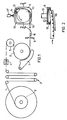
- a film tape 1 is drawn from a supply reel 2 via a loop puller 3, through a punch 4, around a deflection roller 5, from a toothed drum 6 with pressing jaws 7, and through separating knives 8 to cut the film tape from a shaped disk 9 with one thereon attached winding chamber 11 and channels 12, 13 fed offset with a guide element 10 so that the film finally comes to rest after passing through the winding chamber 11 and channel 12 on the suction holes 14 formed as clamping elements of the molded disk 9 after vacuum is switched on.
- windings are inserted into the winding chamber 11 from the outside inwards.
- the now free end of the film tape 1 which is separated by the cutting knife 8 is brought from the toothed drum plane 6 in parallel into the plane of the shaping disk 6 with the aid of a transport arm 16 into abutment with the film beginning, where an endless film wrap is formed by connection with adhesive strips 17 by an adhesive tape mechanism.
- the finished film is pushed into a cassette (not shown) via an ejector 18.
Landscapes
- Physics & Mathematics (AREA)
- General Physics & Mathematics (AREA)
- Replacement Of Web Rolls (AREA)
- Advancing Webs (AREA)
Description
- Die Erfindung betrifft ein Verfahren und eine Vorrichtung zur Konfektionierung einer Kassette mit einem endlosen Wickel aus einem abgelängten Filmband.
- Für manche Filmaufnahmen - zum Beispiel Überblendungen - ist es erforderlich, das Filmband in beide Richtungen bewegen zu können. Eine besonders günstige und raumsparende Anordnung ist der Endlosfilm, bei dem das Filmband über einen Kanal zwischen Kern und Außenwindung durch einen in die Perforierung eingreifenden Filmtransport am Bildfenster zum Belichten vorbeitransportiert wird.
- Bisher wurden solche Endlosfilme manuell durch Herausziehen der Enden eines Filmwickels und Verbinden dieser Enden durch einen Klebestreifen hergestellt und dann in eine flach auf dem Tisch liegende Kassette eingefädelt. Eine solche Handhabung ist bei Massenprodukten, wie z.B. beim Super-8-Film, unwirtschaftlich. Sie erfordert bei der Springfreudigkeit des Filmbandes und der engen gewundenen Kanäle viel Geschick, zumal die Beladung der Kassetten im Dunkeln erfolgen muß.
- Aus der US-Patentschrift 3770551 ist eine Vorrichtung bekannt, welche Band (insbesondere Magnetband) von einer Vorratsspule auf eine Spule einer Bandkassette wickelt. Das vordere Ende des Bandes wird von einer oberen Spindeleinheit erfaßt und durch eine Drehung in die der Kassette entsprechende Lage gebracht. Während der obere Spindlekopf um eine Bandbreite nach oben fährt, wird die Spule mit dem Band von innen nach außen bewickelt. Nachdem die Wicklung vollendet ist, wird das Band von der Vorratsrolle getrennt. Das verbleibende Ende des Bandes wird auf Stoß an das vordere Ende gelegt, gehalten und beide Enden mit einem Klebeband zur Herstellung eines Endloswickels verklebt. Die Vorrichtung wirft dann das Kassettengehäuse mit Spule und Band aus.
- Auch diese, einen Fortschritt gegenüber dem Stand der Technik zeigende Vorrichtung ist für die Aufgabe, ein endloses Band unbelichteten Films in eine Kassette zu wickeln, nicht geeignet. Das Magnetband wird in dieser Vorrichtung auf eine Spule von innen nach außen gewickelt, so daß die einzelnen Wickellagen fest aufeinander liegen. Unbelichtete photographische Filme, wie zum Beispiel Super-8-Filme, würden bei der Herstellung und dem Gebrauch der Kassette stark verschrammen und unbrauchbar werden. Außerdem läßt eine derartige Kassette nicht zu, ein Band störungsfrei in beide Richtungen zu bewegen.
- Der Erfindung liegt die Aufgabe zugrunde, ein Verfahren und eine Vorrichtung zur halb- oder vollautomatischen Beladung einer Kassette mit einem endlosen Filmband zu finden, welche es gestatten, in einer einfachen, betriebssicheren Vorrichtung spulenlose Endloswickel mit lose gewickeltem Filmband herzustellen, die sich in beide Richtungen hin- und herspulen lassen.
- Diese Aufgabe wird erfindungsgemäß dadurch gelöst, daß
- a) das zugeführte Filmband nach Ablenkung auf eine um eine Filmbreite versetzte feststehende Bahn, welche dem Verlauf der Filmführung von der aüßeren Windung eines Wickels zum Bildfenster einer Endloskassette entspricht, zur Fixierung am Ende der Bahn geleitet wird;
- b) weiteres Filmband unter Beibehaltung der Ablenkung zugeführt wird und in eine mit der Bahn verbundene, in ihrer Ebene drehende Wickelkammer, welche der Aufnahme des Wickels in einer Endloskassette entspricht, zu einem Wickel von außen nach innen gewickelt wird;
- c) das nach Beendigung des Wickelvorganges angehaltene Filmband abgeschnitten und mit seinem freien Wickelende unter gleichzeitigem Versatz um eine Filmbreite entlang einer Bahn geführt wird, die der Filmführung von der inneren Windung des Wickels zum Bildfenster einer Endloskassette entspricht und auf Stoß vor das vordere Ende des Bandes gelegt und fixiert wird;
- d) der endlose Wickel in bekannter Weise durch Überkleben des vorderen und hinteren Endes des Bandes mit einem Klebestreifen gebildet wird;
- e) dann der Wickel mit dem endlosen Band durch einen Auswerfer in die parallel angeordnete geöffnete Filmkassette geschoben wird. Die mit der Erfindung erzielten Vorteile
- bestehen insbesondere darin, daß nunmehr der Film entsprechend seiner späteren Lage in der Kassette gewickelt wird, so daß zusätzliche Beanspruchungen des Films, wie sie bei der Wickelwelle auftreten, vermieden werden. Für den Fachmann war es dabei überraschend, daß nach der Einleitung des Versatzes dieser während des gesamten Wickelvorgangs ohne weitere Eingriffe von außen erhalten bleibt. Durch die mehrdimensionale Beigung an der Umlenkstelle wird das Filmband nämlich in der Form so stabilisiert, daß es die einmal eingeschlagene Richtung beibehält, was bei der Labilität und der Springfreudigkeit des Films nicht zu erwarten war. Weiter bietet die umlaufende Wickelkammer den Vorteil, daß jede eingelegte Windung der Zentrifugalkraft unterworfen ist, die das berüchtigte Schwimmen des Wickels weitgehend verhindert. Gleichzeitig sorgt die Rückwand der Wickelkammer für eine saubere Ausrichtung der einzelnen Windungen.
- In einer besonderen Durchführungsart der Verfahren wird die Umfangsgeschwindigkeit der Wickelkammer an der Einlaufstelle des Filmbandes in die Wickelkammer größer gewählt als die Zuführgeschwindigkeit des Filmbandes an dieser Stelle.
- Infolge der besonderen Wickelart von außen nach innen in eine Wickelkammer ist es möglich, durch eine relativ geringere Zuführgeschwindigkeit zur Einlegegeschwindigkeit lockere Wickel sogar mit im Laufe der Wicklung veränderlicher Auflockerung herzustellen. Damit ist eine wichtige Voraussetzung für den späteren Transport von Endlosfilmen erfüllt, denn diese Eigenschaft bleibt auch nach dem Einschieben des Endlosfilmwickels in die Kassette erhalten. Durch diese besondere Möglichkeit des losen Wickelns von Bändern in Endloskassetten ist es möglich, das Band ohne Störungen in beide Richtungen - z.B. bei Überblendungen - hin- und herzuspulen.
- In einer Vorrichtung zur Durchführung des Verfahrens ist als Wickelvorrichtung hinter einem Leitelement eine auf einer Welle stirnseits gelagerte Formscheibe angeordnet, die eine Wickelkammer mit einem an der Peripherie beginnenden Kanal enthält, dessen innere Wandung dem Verlauf eines Kassettenkanals entspricht und dessen äußere Wandung nach einer vorgegebenen Länge vor Klemmelementen endet, die in einer bestimmten Lage der Formscheibe mit einem Klebebandwerk korrespondieren, und es ist ein Tranportarm bewegbar von dem Trennmesser zu den Klemmelementen angeordnet und es befindet sich ein Auswerfer in der Formscheibe.
- Die Vorrichtung ist übersichtlich im Aufbau und deshalb neben der hohen Betriebssicherheit besonders wartungsfreundlich.
- Es kann auch direkt in eine Kasette gewickelt werden. Hierdurch wird das Filmband schonender behandelt, da der Arbeitsgang des Schiebens des fertigen Films in die Kassette mittels des Auswerfers entfällt. Außerdem wird ein Arbeitsgang gespart.
- Ein Ausführungsbeispiel der Erfindung ist in den Zeichnungen dargestellt und wird im folgenden näher beschrieben.
-
- Figur 1 Ansicht einer Wickelstation
- Figur 2 Draufsicht auf eine Filmbandablenkung
- In Fig. 1 und Fig. 2 wird ein Filmband 1 von einer Vorratsspule 2 über einen Schleifenzieher 3 durch eine Stanze 4 um eine Umlenkrolle 5 von einer Zahntrommel 6 mit Andrückbacken 7 gezogen und durch Trennmesser 8 zum Ablängen des Filmbandes einer Formscheibe 9 mit einer darauf angebrachten Wickelkammer 11 und Kanälen 12, 13 unter Versatz über ein Leitelement 10 so zugeführ, daß der Filmanfang schließlich nach Durchlaufen von Wickelkammer 11 und Kanal 12 auf den als Klemmelemente ausgebildeten Saugbohrungen 14 der Formscheibe 9 nach Einschaltung von Vakuum fest zu liegen kommt. Durch Drehung der Formscheibe 9 um Welle 15 bei gleichzeitiger Zuführung des Filmbandes 1 durch die Zahntrommel 6 werden in die Wickelkammer 11 Windungen von außen nach innen eingelegt. Nach Beendigung des Wickelvorganges wird das durch Trennmesser 8 abgetrennte nunmehr freie Ende des Filmbandes 1 mit Hilfe eines Transportarmes 16 von der Zahntrommelebene 6 parallel in die Formscheibenebene auf Stoß zu dem Filmanfang gebracht, wo durch Verbinden mit Klebestreifen durch ein Klebebandwerk 17 ein endloser Filmwickel entsteht.
- Der fertige Film wird über einen Auswerfer 18 in eine Kassette (nicht dargestellt) geschoben.
Claims (4)
Applications Claiming Priority (2)
| Application Number | Priority Date | Filing Date | Title |
|---|---|---|---|
| DE2733585 | 1977-07-26 | ||
| DE19772733585 DE2733585A1 (de) | 1977-07-26 | 1977-07-26 | Verfahren und vorrichtung zur konfektionierung einer kassette mit einem endlosen wickel |
Publications (2)
| Publication Number | Publication Date |
|---|---|
| EP0000712A1 EP0000712A1 (de) | 1979-02-21 |
| EP0000712B1 true EP0000712B1 (de) | 1980-06-25 |
Family
ID=6014821
Family Applications (1)
| Application Number | Title | Priority Date | Filing Date |
|---|---|---|---|
| EP78100437A Expired EP0000712B1 (de) | 1977-07-26 | 1978-07-19 | Verfahren und Vorrichtung zur Konfektionierung einer Kassette mit einem endlosen Wickel |
Country Status (5)
| Country | Link |
|---|---|
| US (1) | US4179079A (de) |
| EP (1) | EP0000712B1 (de) |
| JP (1) | JPS5424626A (de) |
| DE (2) | DE2733585A1 (de) |
| IT (1) | IT7850437A0 (de) |
Families Citing this family (4)
| Publication number | Priority date | Publication date | Assignee | Title |
|---|---|---|---|---|
| EP0566135A1 (de) * | 1992-04-17 | 1993-10-20 | Takeda Chemical Industries, Ltd. | Transmucosale Zubereitungen enthaltend ein Peptid und ein Cytidinderivat |
| US5423495A (en) * | 1993-12-21 | 1995-06-13 | Eastman Kodak Company | Apparatus for winding selectable lengths of web |
| WO2013036130A1 (en) | 2011-09-09 | 2013-03-14 | Universiteit Utrecht Holding B.V. | Broadly neutralizing vhh against hiv-1 |
| CN108854854B (zh) * | 2017-05-16 | 2021-07-20 | 厦门大学 | 一种功能流体门控系统 |
Family Cites Families (7)
| Publication number | Priority date | Publication date | Assignee | Title |
|---|---|---|---|---|
| US2205052A (en) * | 1935-02-23 | 1940-06-18 | Leitz Ernst Gmbh | Device for loading film casettes |
| US2239188A (en) * | 1939-02-09 | 1941-04-22 | Walter W Boes | Film cartridge loader |
| CH486048A (de) * | 1968-04-27 | 1970-02-15 | Agfa Gevaert Ag | Verfahren und Vorrichtung zum Aufspulen eines photographischen Filmbandes auf eine Spule, die innerhalb einer Kassette angeordnet ist |
| US3770551A (en) * | 1969-08-01 | 1973-11-06 | Gen Mills Inc | Splicer tape assembly for use in tape winding machines |
| US3768748A (en) * | 1971-10-01 | 1973-10-30 | I Pfefer | Bulk film loader |
| US3980246A (en) * | 1975-02-26 | 1976-09-14 | Deletzke Jr Norman E H | Automatic tape winding system |
| DE2632767A1 (de) * | 1976-07-21 | 1978-01-26 | Agfa Gevaert Ag | Konfektionierung einer kassette mit endlosem bandwickel |
-
1977
- 1977-07-26 DE DE19772733585 patent/DE2733585A1/de not_active Withdrawn
-
1978
- 1978-07-19 EP EP78100437A patent/EP0000712B1/de not_active Expired
- 1978-07-19 DE DE7878100437T patent/DE2860029D1/de not_active Expired
- 1978-07-19 US US05/926,520 patent/US4179079A/en not_active Expired - Lifetime
- 1978-07-24 JP JP8952578A patent/JPS5424626A/ja active Pending
- 1978-07-24 IT IT7850437A patent/IT7850437A0/it unknown
Also Published As
| Publication number | Publication date |
|---|---|
| DE2860029D1 (en) | 1980-10-30 |
| DE2733585A1 (de) | 1979-02-08 |
| US4179079A (en) | 1979-12-18 |
| IT7850437A0 (it) | 1978-07-24 |
| EP0000712A1 (de) | 1979-02-21 |
| JPS5424626A (en) | 1979-02-24 |
Similar Documents
| Publication | Publication Date | Title |
|---|---|---|
| DE3751440T2 (de) | Vorrichtung zum Befestigen einer Ersatzbahn an eine sich bewegende Bahn. | |
| DE3236866C2 (de) | ||
| DE3786773T2 (de) | Vorrichtung zum automatischen Einfädeln des Vörderendes einer aufgewickelten Bahn in einen Zuführungsdurchlass. | |
| DE3687229T2 (de) | Zufuhrsystem eines bandes zu einer fertigungslinie. | |
| DE2030710B2 (de) | Vorrichtung zum selbsttätigen Überführen des freien Endes eines flexiblen Bandes, wie Film- oder Magnetbandes, von einem Bandträger zu einem anderen Bandträger | |
| DE1424360A1 (de) | Aufnahme-und Wiedergabegeraet | |
| DE2335453C2 (de) | Vorrichtung zur Entnahme des Filmes aus einer Filmpatrone | |
| DE3230001C2 (de) | Videosignal- Aufzeichnungs- und Wiedergabevorrichtung | |
| DE3933013C2 (de) | Einrichtung zum Aufwickeln eines Magnetbandes in einer Kassette | |
| EP0000712B1 (de) | Verfahren und Vorrichtung zur Konfektionierung einer Kassette mit einem endlosen Wickel | |
| DE2718924B2 (de) | Automatisch arbeitende Maschine zur Konfektionierung von Filmkassetten | |
| DE1812211C3 (de) | Vorrichtung zum selbsttätigen Ergreifen und Abziehen des Endes eines Bandwickels | |
| DE69221051T2 (de) | Vorrichtung zum schneiden und zuführen von materialbahn-bändern | |
| DE3737788C2 (de) | Vorrichtung zum automatischen Wechsel der Filmstreifen in einem Rollenkopiergerät | |
| DE3403453A1 (de) | Verfahren zur behandlung eines films | |
| DE2430499A1 (de) | Filmkassette | |
| DE2715605C3 (de) | Einlegeautomat für Rollfilme | |
| DE4226418C2 (de) | Vorrichtung zum Aufwickeln bandförmiger fotografischer Schichtträger | |
| EP0001605B1 (de) | Vorrichtung zum Wickeln eines Filmwickels | |
| DE69021399T2 (de) | Gerät zum Aufspulen von Bandmaterial. | |
| EP0629900B1 (de) | Wickelspule für bandförmiges fotografisches Material | |
| DE2100592B2 (de) | Kassette fuer bandfoermige aufzeichnungstraeger mit zwei ortsfesten wickelkernen | |
| DE2047236A1 (de) | Verfahren und Vorrichtung zur Vorbereitung fotografischer Filme | |
| DE7723269U1 (de) | Vorrichtung zur konfektionierung einer kassette mit einem endlosen wickel | |
| DE4138037C2 (de) | Verfahren zum Bestücken von Bandkassetten mit Magnetband |
Legal Events
| Date | Code | Title | Description |
|---|---|---|---|
| PUAI | Public reference made under article 153(3) epc to a published international application that has entered the european phase |
Free format text: ORIGINAL CODE: 0009012 |
|
| 17P | Request for examination filed | ||
| AK | Designated contracting states |
Designated state(s): BE CH DE FR GB |
|
| GRAA | (expected) grant |
Free format text: ORIGINAL CODE: 0009210 |
|
| AK | Designated contracting states |
Designated state(s): BE CH DE FR GB |
|
| REF | Corresponds to: |
Ref document number: 2860029 Country of ref document: DE Date of ref document: 19801030 |
|
| PGFP | Annual fee paid to national office [announced via postgrant information from national office to epo] |
Ref country code: FR Payment date: 19810630 Year of fee payment: 4 |
|
| PGFP | Annual fee paid to national office [announced via postgrant information from national office to epo] |
Ref country code: DE Payment date: 19810930 Year of fee payment: 4 Ref country code: CH Payment date: 19810930 Year of fee payment: 4 Ref country code: BE Payment date: 19810930 Year of fee payment: 4 |
|
| PG25 | Lapsed in a contracting state [announced via postgrant information from national office to epo] |
Ref country code: CH Effective date: 19820731 |
|
| PG25 | Lapsed in a contracting state [announced via postgrant information from national office to epo] |
Ref country code: BE Effective date: 19830119 |
|
| PG25 | Lapsed in a contracting state [announced via postgrant information from national office to epo] |
Ref country code: FR Free format text: LAPSE BECAUSE OF NON-PAYMENT OF DUE FEES Effective date: 19830331 |
|
| REG | Reference to a national code |
Ref country code: CH Ref legal event code: PL |
|
| PG25 | Lapsed in a contracting state [announced via postgrant information from national office to epo] |
Ref country code: DE Effective date: 19830401 |
|
| REG | Reference to a national code |
Ref country code: FR Ref legal event code: ST |
|
| GBPC | Gb: european patent ceased through non-payment of renewal fee | ||
| PG25 | Lapsed in a contracting state [announced via postgrant information from national office to epo] |
Ref country code: GB Effective date: 19881117 |
|
| PLBE | No opposition filed within time limit |
Free format text: ORIGINAL CODE: 0009261 |
|
| STAA | Information on the status of an ep patent application or granted ep patent |
Free format text: STATUS: NO OPPOSITION FILED WITHIN TIME LIMIT |