DE102010047800A1 - Hydrostatic clutch actuator - Google Patents
Hydrostatic clutch actuator Download PDFInfo
- Publication number
- DE102010047800A1 DE102010047800A1 DE102010047800A DE102010047800A DE102010047800A1 DE 102010047800 A1 DE102010047800 A1 DE 102010047800A1 DE 102010047800 A DE102010047800 A DE 102010047800A DE 102010047800 A DE102010047800 A DE 102010047800A DE 102010047800 A1 DE102010047800 A1 DE 102010047800A1
- Authority
- DE
- Germany
- Prior art keywords
- housing
- pressure chamber
- electric motor
- piston
- transmission
- Prior art date
- Legal status (The legal status is an assumption and is not a legal conclusion. Google has not performed a legal analysis and makes no representation as to the accuracy of the status listed.)
- Withdrawn
Links
Images


Classifications
-
- F—MECHANICAL ENGINEERING; LIGHTING; HEATING; WEAPONS; BLASTING
- F16—ENGINEERING ELEMENTS AND UNITS; GENERAL MEASURES FOR PRODUCING AND MAINTAINING EFFECTIVE FUNCTIONING OF MACHINES OR INSTALLATIONS; THERMAL INSULATION IN GENERAL
- F16D—COUPLINGS FOR TRANSMITTING ROTATION; CLUTCHES; BRAKES
- F16D29/00—Clutches and systems of clutches involving both fluid and magnetic actuation
- F16D29/005—Clutches and systems of clutches involving both fluid and magnetic actuation with a fluid pressure piston driven by an electric motor
-
- F—MECHANICAL ENGINEERING; LIGHTING; HEATING; WEAPONS; BLASTING
- F15—FLUID-PRESSURE ACTUATORS; HYDRAULICS OR PNEUMATICS IN GENERAL
- F15B—SYSTEMS ACTING BY MEANS OF FLUIDS IN GENERAL; FLUID-PRESSURE ACTUATORS, e.g. SERVOMOTORS; DETAILS OF FLUID-PRESSURE SYSTEMS, NOT OTHERWISE PROVIDED FOR
- F15B7/00—Systems in which the movement produced is definitely related to the output of a volumetric pump; Telemotors
- F15B7/06—Details
- F15B7/08—Input units; Master units
-
- F—MECHANICAL ENGINEERING; LIGHTING; HEATING; WEAPONS; BLASTING
- F16—ENGINEERING ELEMENTS AND UNITS; GENERAL MEASURES FOR PRODUCING AND MAINTAINING EFFECTIVE FUNCTIONING OF MACHINES OR INSTALLATIONS; THERMAL INSULATION IN GENERAL
- F16H—GEARING
- F16H25/00—Gearings comprising primarily only cams, cam-followers and screw-and-nut mechanisms
- F16H25/18—Gearings comprising primarily only cams, cam-followers and screw-and-nut mechanisms for conveying or interconverting oscillating or reciprocating motions
- F16H25/20—Screw mechanisms
- F16H25/22—Screw mechanisms with balls, rollers, or similar members between the co-operating parts; Elements essential to the use of such members
- F16H25/2247—Screw mechanisms with balls, rollers, or similar members between the co-operating parts; Elements essential to the use of such members with rollers
- F16H25/2252—Planetary rollers between nut and screw
-
- F—MECHANICAL ENGINEERING; LIGHTING; HEATING; WEAPONS; BLASTING
- F16—ENGINEERING ELEMENTS AND UNITS; GENERAL MEASURES FOR PRODUCING AND MAINTAINING EFFECTIVE FUNCTIONING OF MACHINES OR INSTALLATIONS; THERMAL INSULATION IN GENERAL
- F16H—GEARING
- F16H25/00—Gearings comprising primarily only cams, cam-followers and screw-and-nut mechanisms
- F16H25/18—Gearings comprising primarily only cams, cam-followers and screw-and-nut mechanisms for conveying or interconverting oscillating or reciprocating motions
- F16H25/20—Screw mechanisms
- F16H2025/2062—Arrangements for driving the actuator
- F16H2025/2075—Coaxial drive motors
- F16H2025/2078—Coaxial drive motors the rotor being integrated with the nut or screw body
Landscapes
- Engineering & Computer Science (AREA)
- General Engineering & Computer Science (AREA)
- Mechanical Engineering (AREA)
- Physics & Mathematics (AREA)
- Fluid Mechanics (AREA)
- Hydraulic Clutches, Magnetic Clutches, Fluid Clutches, And Fluid Joints (AREA)
- Braking Systems And Boosters (AREA)
- Connection Of Motors, Electrical Generators, Mechanical Devices, And The Like (AREA)
- Retarders (AREA)
- Transmission Devices (AREA)
Abstract
Die Erfindung betrifft einen Hydrostataktor, insbesondere einen hydrostatischen Kupplungsaktor mit einem Geberzylinder enthaltend ein Gehäuse und einen in dem Gehäuse axial verlagerbaren, eine Druckkammer mit Druck beaufschlagenden Kolben, mit einem einen Drehantrieb in eine Axialbewegung wandelnden Getriebe sowie mit einem das Getriebe drehantreibenden Elektromotor mit einem Stator und einem Rotor. Zur Begrenzung des Bauraums werden die Bauteile des Hydrostataktors bauraumsparend ineinander integriert.The invention relates to a Hydrostataktor, in particular a hydrostatic clutch actuator with a master cylinder containing a housing and an axially displaceable in the housing, a pressure chamber with pressure acting piston, with a rotary drive in an axial movement conversion gear and a gearbox rotationally driving the electric motor with a stator and a rotor. To limit the space, the components of Hydrostataktors space-saving integration into each other.

Description
Die Erfindung betrifft einen Hydrostataktor, insbesondere einen hydrostatischen Kupplungsaktor mit einem Geberzylinder enthaltend ein Gehäuse und einen in dem Gehäuse axial verlagerbaren, eine Druckkammer mit Druck beaufschlagenden Kolben, mit einem einen Drehantrieb in eine Axialbewegung wandelnden Getriebe sowie mit einem das Getriebe drehantreibenden Elektromotor mit einem Stator und einem Rotor.The invention relates to a Hydrostataktor, in particular a hydrostatic clutch actuator with a master cylinder containing a housing and an axially displaceable in the housing, a pressure chamber with pressure acting piston, with a rotary drive in an axial movement conversion gear and a gearbox rotationally driving the electric motor with a stator and a rotor.
Ein gattungsgemäßer Hydrostataktor ist in Form eines hydrostatischen Kupplungsaktors aus der
Die Aufgabe der Erfindung ist die Verbesserung und Weiterentwicklung derartiger Hydrostataktoren insbesondere vor dem Hintergrund einer Erhöhung des Wirkungsgrades, der Verringerung des Bauraumbedarfs und der Erhöhung des Betriebsdrucks des Geberzylinders.The object of the invention is the improvement and further development of such Hydrostataktoren particular against the background of an increase in efficiency, reducing the space requirement and increasing the operating pressure of the master cylinder.
Die Aufgabe wird durch einen Hydrostataktor, insbesondere durch einen hydrostatischen Kupplungsaktor mit einem Geberzylinder enthaltend ein Gehäuse und einen in dem Gehäuse axial verlagerbaren, eine Druckkammer mit Druck beaufschlagenden Kolben, mit einem einen Drehantrieb in eine Axialbewegung wandelnden Getriebe sowie mit einem das Getriebe drehantreibenden Elektromotor mit einem Stator und einem Rotor gelöst, wobei der Kolben bezogen auf eine Drehachse des Elektromotors axial zwischen Druckammer und Elektromotor angeordnet ist.The object is achieved by a Hydrostataktor, in particular by a hydrostatic clutch actuator with a master cylinder containing a housing and an axially displaceable in the housing, a pressure chamber with pressure acting piston, with a rotary drive in an axial movement converting gear and with a rotationally driving the electric motor a stator and a rotor dissolved, wherein the piston is arranged axially relative to a rotational axis of the electric motor between the pressure chamber and the electric motor.
Alternativ wird die Aufgabe durch einen Hydrostataktor, insbesondere durch einen hydrostatischen Kupplungsaktor mit einem Geberzylinder enthaltend ein Gehäuse und einen in dem Gehäuse axial verlagerbaren, eine Druckkammer mit Druck beaufschlagenden Kolben, mit einem einen Drehantrieb in eine Axialbewegung wandelnden Getriebe sowie mit einem das Getriebe drehantreibenden Elektromotor mit einem Stator und einem Rotor gelöst, wobei die Druckkammer bezogen auf eine Drehachse des Elektromotors axial zwischen Kolben und Elektromotor angeordnet ist. Bei Verwendung einer derartigen Anordnung wird bei der Komprimierung der Druckkammer durch den Kolben das Gehäuse des Geberzylinders in Richtung Elektromotor belastet. Dabei wird der Kolben gegen den Elektromotor gezogen, indem das Getriebe auf den Kolben eine Zugkraft ausübt. Beispielsweise kann eine Getriebespindel des Getriebes mit dem Kolben einteilig verbunden sein. Dabei hat es sich als vorteilhaft erwiesen, wenn der Kolben als Ringkolben in einer ringförmig ausgebildeten Druckkammer verlagert wird.Alternatively, the object is achieved by a hydrostatic actuator, in particular by a hydrostatic clutch actuator with a master cylinder containing a housing and a piston axially displaceable in the housing, a pressure chamber with pressure acting piston, with a rotary drive in an axial movement conversion gear and with a gearbox rotationally driving electric motor solved with a stator and a rotor, wherein the pressure chamber is arranged axially relative to a rotational axis of the electric motor between the piston and the electric motor. When using such an arrangement, the housing of the master cylinder is loaded in the direction of the electric motor during the compression of the pressure chamber by the piston. The piston is pulled against the electric motor by the transmission exerts a pulling force on the piston. For example, a gear spindle of the transmission can be integrally connected to the piston. It has proved to be advantageous if the piston is displaced as an annular piston in a ring-shaped pressure chamber.
Die vorgeschlagenen Hydrostataktoren können neben einer Anwendung zur Betätigung einer Reibungskupplung für weitere Bewegungsvorgänge insbesondere in einem Kraftfahrzeug eingesetzt werden, bei dem hohe Kräfte mit einem vergleichsweise kleinen Elektromotor umgesetzt werden müssen. Hierzu zählen beispielsweise und nicht abschließend die Betätigung von Bremsen wie Betriebs- und Feststellbremsen, Getriebebetätigungen, Parksperren, Tür- und Klappenbetätigungen und dergleichen.The proposed Hydrostataktoren can be used in addition to an application for actuating a friction clutch for further movement processes, especially in a motor vehicle, in which high forces must be implemented with a comparatively small electric motor. These include, but are not limited to, the operation of brakes such as service and parking brakes, transmission actuations, parking locks, door and door actuation, and the like.
Als Getriebe eignen sich Spindelgetriebe mit einer den Kolben axial antreibenden und wahlweise mit diesem einteilig verbundenen Spindel und einer Spindelmutter, die aus einer Hülse gebildet sein kann, die direkt von dem Rotor des Elektromotors angetrieben oder aus diesem gebildet sein kann. Weiterhin kann zur Verminderung der Reibung die Spindel als Kugelumlaufspindel vorgesehen sein. Es hat sich als besonders vorteilhaft erwiesen, wenn das Getriebe als Planetenwälzgetriebe enthaltend eine den Kolben axial verlagernde, entlang der Drehachse angeordnete Gewindespindel, eine koaxial zu dieser angeordnete drehangetriebene Hülse und zwischen diesen abwälzende Planetenräder gebildet und beispielsweise in der
Insbesondere zur Verringerung des axialen Bauraums kann das Getriebe wie Planetenwälzgetriebe radial innerhalb des Rotors angeordnet sein. Dabei kann der Rotor auf dem Getriebe, beispielsweise der Hülse eines Planetenwälzgetriebes gelagert sein. Dabei kann das komplette Getriebe in dem Bauraum des Rotors untergebracht sein. Dabei können die Funktionen des Rotors und der Hülse miteinander kombiniert sein. Beispielsweise kann ein Blechaufbau des Rotors entfallen, indem die Permanentmagnete des Rotors direkt an der Hülse aufgenommen, beispielsweise mit dieser verklebt werden. Im Weiteren kann das Getriebe in den Rotor integriert sein, indem beispielsweise der Rotor die Innenverzahnung für die Planeten eines Planetenwälzgetriebes bildet.In particular, in order to reduce the axial space, the transmission can be arranged like Planetenwälzgetriebe radially inside the rotor. In this case, the rotor may be mounted on the transmission, for example, the sleeve of a Planetenwälzgetriebes. In this case, the entire transmission can be accommodated in the space of the rotor. The functions of the rotor and the sleeve can be combined with each other. For example, a sheet metal structure of the rotor can be omitted by the permanent magnets of the rotor are received directly on the sleeve, for example glued to it. Furthermore, the transmission can be integrated into the rotor, for example by the rotor forming the internal toothing for the planets of a Planetenwälzgetriebes.
Zur Erzielung besonders kompakter Hydrostataktoren, können die Bauteile beziehungsweise Baugruppen des Hydrostataktors ineinander geschachtelt sein. Beispielsweise kann ein die Druckkammer bildender Gehäuseabschnitt des Geberzylindergehäuses radial außerhalb des Getriebes angeordnet sein und der Elektromotor axial benachbart zu der Druckkammer angeordnet sein. Als vorteilhaft hat sich hierbei erwiesen, wenn der Elektromotor einen kleineren Durchmesser als der Außendurchmesser der Druckkammer, beziehungsweise des diese bildenden Gehäuseabschnitts aufweist.To achieve particularly compact Hydrostataktoren, the components or assemblies of Hydrostataktors can be nested. For example, a pressure chamber forming the housing portion of the master cylinder housing radially outside of the transmission be arranged and the electric motor to be arranged axially adjacent to the pressure chamber. It has proven to be advantageous in this case if the electric motor has a smaller diameter than the outer diameter of the pressure chamber, or of the housing section forming this.
Es hat sich weiterhin als vorteilhaft gezeigt, wenn in den Hydrostataktor ein Nachlaufbehälter für ein hydrostatisches Druckmittel in bevorzugter Weise bauraumneutral, das heißt, in einen von dem Elektromotor, dem Getriebe und dem Gehäuse des Geberzylinders vorgegebenen, vorzugsweise um eine Drehachse des Elektromotors zylindrisch angeordneten Bauraum integriert ist.It has also been found to be advantageous if in the Hydrostataktor a reservoir for a hydrostatic pressure fluid in a preferred manner space neutral, that is, in a predetermined by the electric motor, the transmission and the housing of the master cylinder, preferably cylindrical about a rotational axis of the electric motor arranged space is integrated.
Der Nachlaufbehälter kann über eine sogenannte Schnüffelbohrung mit der Druckkammer verbunden sein, die im entspannten Zustand des Kolbens mit dieser verbunden und bei Druckbeaufschlagung der Druckkammer durch den Kolben verschlossen wird. Der Nachlaufbehälter kann bei einer im eingebauten Zustand über der Druckkammer vorgesehenen Anordnung mit der Umgebung im Druckgleichgewicht stehen, so dass das Druckmittel hydrostatisch nachläuft, oder mittels einer Membran wie Balgen oder einer Druckfeder vorgespannt sein, so dass das Druckmittel bei Bedarf unter leichtem Überdruck in die Druckkammer nachgeführt wird.The follow-up container may be connected via a so-called sniffer bore with the pressure chamber, which is connected in the relaxed state of the piston with this and is closed by the piston when pressure is applied to the pressure chamber. The follow-up container can be at a pressure in the installed state with the environment with the environment in the pressure equilibrium, so that the pressure medium hydrostatically trailing, or be biased by a diaphragm such as bellows or a compression spring, so that the pressure medium when needed under slight overpressure in the Pressure chamber is tracked.
Als besonders vorteilhaft hat sich bei einer ringförmig ausgebildeten Druckkammer erwiesen, wenn der Nachlaufbehälter radial innerhalb der Druckkammer beispielsweise in dem von der Kolbenstange und dem Innenumfang des Gehäuses des Geberzylinders freigelassenen Bauraum angeordnet ist. Dabei kann die Kolbenstange beziehungsweise eine mit dieser fest verbundene oder einteilig ausgebildete Gewindespindel des Getriebes während einer Verlagerung des Kolbens zumindest teilweise axial in den Nachlaufbehälter eingreifen.It has proved to be particularly advantageous in the case of an annular pressure chamber when the after-reservoir is arranged radially inside the pressure chamber, for example in the space left free by the piston rod and the inner circumference of the housing of the master cylinder. In this case, the piston rod or a firmly connected to this or integrally formed threaded spindle of the transmission during a displacement of the piston at least partially axially engage in the follower tank.
Gemäß einer alternativen Ausführungsform kann der Nachlaufbehälter radial außerhalb einer ringförmig ausgebildeten Druckkammer angeordnet sein. Dabei kann der Durchmesser des Nachlaufbehälters radial auf den Außendurchmesser des Elektromotors oder eines anderen bauraumbedingt den Durchmesser des Hydrostataktors vorgebenden Bauteils beschränkt werden.According to an alternative embodiment, the follow-up container can be arranged radially outside of an annular pressure chamber. In this case, the diameter of the follow-up container can be limited radially to the outer diameter of the electric motor or other space-dictating the diameter of the Hydrostataktors predetermining component.
Zur Abdichtung einer Leckage des Geberzylinders nach außen kann zwischen dem Gehäuse und dem Kolben eine Leckagedichtung, beispielsweise eine Lippendichtung oder ein Faltenbalg vorgesehen sein. Alternativ kann die Leckagedichtung zwischen dem Gehäuse und dem Getriebe und/oder zwischen einer Getriebespindel des Getriebes und dem Gehäuse angeordnet sein.To seal a leakage of the master cylinder to the outside, a leakage seal, such as a lip seal or a bellows may be provided between the housing and the piston. Alternatively, the leakage seal may be disposed between the housing and the transmission and / or between a transmission spindle of the transmission and the housing.
Gemäß einer vorteilhaften Ausführungsvariante eines Hydrostataktors können das Gehäuse des Geberzylinders und die Hülse des Planetenwälzgetriebes einteilig, beispielsweise aus Blech gezogen ausgebildet sein. Dabei können der Geberzylinder und das Planetenwälzgetriebe als Baueinheit ausgebildet sein.According to an advantageous embodiment of a Hydrostataktors the housing of the master cylinder and the sleeve of the Planetenwälzgetriebes can be integrally formed, drawn for example from sheet metal. In this case, the master cylinder and the planetary gear can be designed as a unit.
In dem Hydrostataktor ist eine Sensoreinrichtung vorgesehen, die zumindest die Drehbewegung des Elektromotors erfasst und die Daten für die Kommutierung des vorzugsweise als bürstenloser Elektromotor vorgesehenen Elektromotors liefert. Zusätzlich kann mittels zusätzlicher oder der in der Sensoreinrichtung vorgesehenen Sensoren der Axialweg des Kolbens erfasst und ermittelt werden. Weiterhin kann die Sensoreinrichtung zur Ermittlung des Schlupfs des Planetenwälzgetriebes dienen. Die Daten werden dabei in ein Steuergerät des Hydrostataktors eingelesen und in diesem verarbeitet. Dabei kann die Sensoreinrichtung die Signale direkt auf das Steuergerät übertragen oder über eine Vorortelektronik verfügen, die entsprechende Signale aufbereitet und gewandelt auf das Steuergerät überträgt. Das Steuergerät kann in den Hydrostataktor, beispielsweise in den Elektromotor integriert oder an diesen angebaut sein. Die Anordnung der Sensoreinrichtung kann an der der das Gehäuse des Geberzylinders aufnehmenden Stirnseite gegenüberliegenden Stirnseite oder an der das Gehäuse des Geberzylinders aufnehmenden Stirnseite, beispielsweise zwischen dem Gehäuse des Geberzylinders und dem Gehäuse des Elektromotors angeordnet sein.In the Hydrostataktor a sensor device is provided which detects at least the rotational movement of the electric motor and supplies the data for the commutation of the preferably provided as a brushless electric motor electric motor. In addition, the axial travel of the piston can be detected and determined by means of additional sensors or sensors provided in the sensor device. Furthermore, the sensor device can be used to determine the slip of the planetary roller gear. The data are read into a control unit of the Hydrostataktors and processed in this. In this case, the sensor device can transmit the signals directly to the control unit or have on-site electronics, which processes the corresponding signals and converted converted to the control unit. The control unit can be integrated in the hydrostatic actuator, for example in the electric motor or attached thereto. The arrangement of the sensor device can be arranged on the front side opposite the housing of the master cylinder receiving end face or on the housing of the master cylinder receiving end face, for example, between the housing of the master cylinder and the housing of the electric motor.
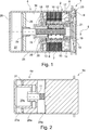
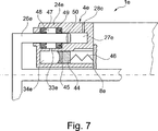
Die Erfindung wird anhand der in den
und
and
In dem gezeigten Ausführungsbeispiel ist das Planetenwälzgetriebe
Der Geberzylinder
Die Druckkammer
Die
Die
BezugszeichenlisteLIST OF REFERENCE NUMBERS
- 11
- HydrostataktorHydrostataktor
- 1a1a
- HydrostataktorHydrostataktor
- 1b1b
- HydrostataktorHydrostataktor
- 1c1c
- HydrostataktorHydrostataktor
- 1d1d
- HydrostataktorHydrostataktor
- 1e1e
- HydrostataktorHydrostataktor
- 22
- Elektromotorelectric motor
- 33
- PlanetenwälzgetriebePlanetenwälzgetriebe
- 44
- GeberzylinderMaster cylinder
- 4a4a
- GeberzylinderMaster cylinder
- 4b4b
- GeberzylinderMaster cylinder
- 4c4c
- GeberzylinderMaster cylinder
- 4d4d
- GeberzylinderMaster cylinder
- 4e4e
- GeberzylinderMaster cylinder
- 55
- Drehachseaxis of rotation
- 66
- Rotorrotor
- 77
- Statorstator
- 88th
- Gehäusecasing
- 8d8d
- Gehäusecasing
- 8e8e
- Gehäusecasing
- 99
- Deckelcover
- 1010
- Hülseshell
- 10a10a
- Hülseshell
- 10d10d
- Hülseshell
- 1111
- Getriebespindelgear spindle
- 1212
- Planetenwälzkörperplanet rolling
- 1313
- Grobverzahnungcoarse teeth
- 1414
- Innenverzahnunginternal gearing
- 1515
- FeingewindeabschnittFinely threaded portion
- 1616
- Außengewindeexternal thread
- 1717
- Permanentmagnetpermanent magnet
- 1818
- Ansatzapproach
- 1919
- Ansatzapproach
- 2020
- Wälzlagerroller bearing
- 2121
- Wälzlagerroller bearing
- 2222
- Gehäuseabschnitthousing section
- 2323
- Einsatzcommitment
- 2424
- Gehäusecasing
- 24a24a
- Gehäusecasing
- 24b24b
- Gehäusecasing
- 24c24c
- Gehäusecasing
- 24d24d
- Gehäusecasing
- 24e24e
- Gehäusecasing
- 2525
- Zentrierbundspigot
- 2626
- Kolbenpiston
- 26a26a
- Kolbenpiston
- 26b26b
- Kolbenpiston
- 26c26c
- Kolbenpiston
- 26d26d
- Kolbenpiston
- 26e26e
- Kolbenpiston
- 2727
- Druckkammerpressure chamber
- 27a27a
- Druckkammerpressure chamber
- 27b27b
- Druckkammerpressure chamber
- 27c27c
- Druckkammerpressure chamber
- 27d27d
- Druckkammerpressure chamber
- 27e27e
- Druckkammerpressure chamber
- 2828
- Druckanschlusspressure connection
- 28c28c
- Druckanschlusspressure connection
- 28e28e
- Druckanschlusspressure connection
- 2929
- Axialführungaxial guidance
- 3030
- Freiraumfree space
- 30a30a
- Freiraumfree space
- 30d30d
- Freiraumfree space
- 3131
- Kolbenflächepiston area
- 3232
- Baueinheitunit
- 3333
- NachlaufbehälterAn expansion reservoir
- 33e33e
- NachlaufbehälterAn expansion reservoir
- 3434
- Nachlauföffnungtrailing opening
- 34e34e
- Nachlauföffnungtrailing opening
- 3535
- Befüllöffnungfilling
- 3636
- KugelBullet
- 3737
- Membranmembrane
- 3838
- Öffnungopening
- 38a38a
- Abdeckungcover
- 3939
- Sensoreinrichtungsensor device
- 4040
- Sensorsensor
- 4141
- Sensorsensor
- 4242
- Sensormagnetsensor magnet
- 4343
- Vorortelektroniksite electronics
- 4444
- Kolbenpiston
- 4545
- Dichtungpoetry
- 4646
- Energiespeicherenergy storage
- 4747
- Dichtungsabschnittsealing section
- 4848
- Nutringdichtunggroove ring seal
- 4949
- Nutringdichtunggroove ring seal
- 5050
- SchnüffelnutSchnüffelnut
ZITATE ENTHALTEN IN DER BESCHREIBUNG QUOTES INCLUDE IN THE DESCRIPTION
Diese Liste der vom Anmelder aufgeführten Dokumente wurde automatisiert erzeugt und ist ausschließlich zur besseren Information des Lesers aufgenommen. Die Liste ist nicht Bestandteil der deutschen Patent- bzw. Gebrauchsmusteranmeldung. Das DPMA übernimmt keinerlei Haftung für etwaige Fehler oder Auslassungen.This list of the documents listed by the applicant has been generated automatically and is included solely for the better information of the reader. The list is not part of the German patent or utility model application. The DPMA assumes no liability for any errors or omissions.
Zitierte PatentliteraturCited patent literature
- DE 19700935 A1 [0002] DE 19700935 A1 [0002]
- EP 0320621 A1 [0007, 0025] EP 0320621 A1 [0007, 0025]
- DE 19540634 C1 [0025] DE 19540634 C1 [0025]
Claims (10)
Priority Applications (1)
| Application Number | Priority Date | Filing Date | Title |
|---|---|---|---|
| DE102010047800A DE102010047800A1 (en) | 2009-10-29 | 2010-10-07 | Hydrostatic clutch actuator |
Applications Claiming Priority (5)
| Application Number | Priority Date | Filing Date | Title |
|---|---|---|---|
| DE102009051244.6 | 2009-10-29 | ||
| DE102009051244 | 2009-10-29 | ||
| DE102010009297 | 2010-02-25 | ||
| DE102010009297.5 | 2010-02-25 | ||
| DE102010047800A DE102010047800A1 (en) | 2009-10-29 | 2010-10-07 | Hydrostatic clutch actuator |
Publications (1)
| Publication Number | Publication Date |
|---|---|
| DE102010047800A1 true DE102010047800A1 (en) | 2011-05-05 |
Family
ID=43531005
Family Applications (2)
| Application Number | Title | Priority Date | Filing Date |
|---|---|---|---|
| DE102010047800A Withdrawn DE102010047800A1 (en) | 2009-10-29 | 2010-10-07 | Hydrostatic clutch actuator |
| DE112010004220T Withdrawn DE112010004220A5 (en) | 2009-10-29 | 2010-10-07 | Hydrostatic clutch actuator |
Family Applications After (1)
| Application Number | Title | Priority Date | Filing Date |
|---|---|---|---|
| DE112010004220T Withdrawn DE112010004220A5 (en) | 2009-10-29 | 2010-10-07 | Hydrostatic clutch actuator |
Country Status (8)
| Country | Link |
|---|---|
| US (1) | US9051974B2 (en) |
| EP (1) | EP2494228B1 (en) |
| JP (1) | JP5734303B2 (en) |
| KR (1) | KR101798250B1 (en) |
| CN (1) | CN102575730B (en) |
| DE (2) | DE102010047800A1 (en) |
| RU (1) | RU2570244C2 (en) |
| WO (1) | WO2011050766A1 (en) |
Cited By (78)
| Publication number | Priority date | Publication date | Assignee | Title |
|---|---|---|---|---|
| WO2012139547A1 (en) | 2011-04-15 | 2012-10-18 | Schaeffler Technologies AG & Co. KG | Method for commissioning a clutch |
| WO2012139546A1 (en) | 2011-04-15 | 2012-10-18 | Schaeffler Technologies AG & Co. KG | Method for adapting parameters of a clutch |
| DE102012206306A1 (en) | 2011-05-05 | 2012-11-08 | Schaeffler Technologies AG & Co. KG | Actuating device for a double clutch |
| DE102011083329A1 (en) | 2011-09-23 | 2013-03-28 | Schaeffler Technologies AG & Co. KG | Device for compensation of plucking oscillations of friction clutch in motor car, has acceleration sensor for detecting plucking oscillations of clutch, where electronic unit and actuator partially compensates oscillations of clutch |
| DE102011085129A1 (en) | 2011-10-24 | 2013-04-25 | Schaeffler Technologies AG & Co. KG | Device for e.g. start-up of vehicle transmission with gear box actuator in dual-clutch transmission system of motor vehicle, has clutch actuators controlled by computer so that gear box and clutch start-ups are implemented independently |
| DE102012218252A1 (en) | 2011-10-24 | 2013-04-25 | Schaeffler Technologies AG & Co. KG | Method for starting transmission of dual-clutch transmission system in motor car, involves transferring data from non-volatile storage area to storage area of control unit using diagnostic command, when specific condition is satisfied |
| DE102011085127A1 (en) | 2011-10-24 | 2013-04-25 | Schaeffler Technologies AG & Co. KG | Device for operating dual clutch e.g. wet dual clutch, in power train of motor car, has pressure relief valve designed as spring force actuated check valve for limiting maximum pressure value to predetermined level |
| DE102012220179A1 (en) | 2011-11-24 | 2013-05-29 | Schaeffler Technologies AG & Co. KG | Method for checking correct filling of e.g. hydraulic clutch operating system with pressurizing medium in motor vehicle, involves ensuring correct filling of system when pressure gradient is larger than given pressure gradient level |
| WO2013075687A2 (en) | 2011-11-24 | 2013-05-30 | Schaeffler Technologies AG & Co. KG | Hydraulic actuating system |
| DE102012220177A1 (en) | 2012-01-03 | 2013-07-04 | Schaeffler Technologies AG & Co. KG | Method for checking correct filling of e.g. hydraulic clutch actuating system, involves determining whether two position-pressure characteristics are present, when determined maximum pressure gradient is greater than preset value |
| DE102012220178A1 (en) | 2012-01-26 | 2013-08-01 | Schaeffler Technologies AG & Co. KG | Method for checking correct filling of e.g. hydraulic clutch actuating system, involves determining whether two position-pressure characteristics are present, when determined maximum pressure gradient is greater than preset value |
| DE102013201566A1 (en) | 2012-02-22 | 2013-08-22 | Schaeffler Technologies AG & Co. KG | Method for determining and / or compensating a crosstalk behavior of a dual-clutch transmission |
| DE102013201933A1 (en) | 2012-02-22 | 2013-08-22 | Schaeffler Technologies AG & Co. KG | Method for checking software compatibility of control devices, involves completing review as correct, if software version identifiers of checked control devices are valid and equal, and/or both are considered as valid |
| DE102012203813A1 (en) | 2012-03-12 | 2013-09-12 | Schaeffler Technologies AG & Co. KG | Method for operating of actuating system e.g. dual clutch actuating system of motor car, involves reading operational parameters stored in non-volatile memories of main control apparatus and actuators from non-volatile memories |
| DE102013202700A1 (en) | 2012-03-12 | 2013-09-12 | Schaeffler Technologies AG & Co. KG | Planetary roller gearbox for use classical spindle drive in hydrostatic actuator, has planetary carrier rotationally blocked with respect to spindle nut by locking device, and planetary rolling elements arranged at planetary carrier |
| DE102013205237A1 (en) | 2012-04-16 | 2013-10-17 | Schaeffler Technologies AG & Co. KG | Actuator system for hydraulic clutch actuation |
| DE102013207263A1 (en) | 2012-05-08 | 2013-11-14 | Schaeffler Technologies AG & Co. KG | Method for adjusting clutch characteristic curve of automatically actuated friction clutch, involves determining touch point change of friction clutch in operating phases before pressure- or volume compensation |
| DE102012212282A1 (en) | 2012-07-13 | 2014-01-16 | Schaeffler Technologies AG & Co. KG | Method for braking motor vehicle, involves connecting engaged gear having sub-drive train to internal combustion engine by closed clutch during travel of motor vehicle, and braking motor vehicle by closing another clutch in overrun mode |
| DE102013213900A1 (en) | 2012-07-17 | 2014-01-23 | Schaeffler Technologies AG & Co. KG | Method for determining parameters of a friction clutch device |
| FR2993949A1 (en) * | 2012-07-25 | 2014-01-31 | Renault Sa | Electrohydraulic device for controlling clutch of automatic gear box of car, has mechanical converter arranged to reduce rotation movement of electrical motor and its transformation into thrust on control piston of transmitting jack |
| DE102013211080A1 (en) | 2012-06-26 | 2014-05-08 | Schaeffler Technologies Gmbh & Co. Kg | Method for controlling a motor vehicle transmission |
| DE102012220076A1 (en) | 2012-11-05 | 2014-05-08 | Schaeffler Technologies Gmbh & Co. Kg | Method for determining failure of pressure sensor in hydrostatic clutch actuator used in motor vehicle, involves detecting failure of sensor by comparing measured value of sensor signal with reference value |
| DE102012223765A1 (en) | 2012-12-19 | 2014-06-26 | Schaeffler Technologies Gmbh & Co. Kg | Method for stabilizing a coefficient of friction gradient of a clutch in a motor vehicle |
| DE102014201791A1 (en) | 2013-02-27 | 2014-08-28 | Schaeffler Technologies Gmbh & Co. Kg | Hydraulic fact actuator for automated operation of a friction clutch used in powertrain of motor car, changes rotating movement of rotor of electromotor corresponding to linear shift movement of piston and rotation speed of rotor |
| DE102014203219A1 (en) | 2013-03-18 | 2014-09-18 | Schaeffler Technologies Gmbh & Co. Kg | Method for determining a pilot control voltage of an electric motor in a hydrostatically actuated clutch system, preferably in an automated manual transmission of a motor vehicle |
| DE102013213888B3 (en) * | 2013-07-16 | 2014-11-13 | Robert Bosch Gmbh | Electrohydraulic actuator |
| WO2015018408A2 (en) | 2013-08-09 | 2015-02-12 | Schaeffler Technologies Gmbh & Co. Kg | Method for positioning a piston |
| DE102014218895A1 (en) | 2013-10-04 | 2015-04-09 | Schaeffler Technologies Gmbh & Co. Kg | clutch maintenance |
| WO2015048961A2 (en) | 2013-10-01 | 2015-04-09 | Schaeffler Technologies AG & Co. KG | Assembly with friction arrangement |
| WO2015070850A1 (en) | 2013-11-18 | 2015-05-21 | Schaeffler Technologies AG & Co. KG | Torque support of an actuator on a clutch housing/ transmission housing |
| WO2015081950A2 (en) | 2013-12-06 | 2015-06-11 | Schaeffler Technologies AG & Co. KG | Actuator having a gear mechanism converting a rotary motion into a linear motion |
| WO2015081951A1 (en) | 2013-12-06 | 2015-06-11 | Schaeffler Technologies AG & Co. KG | Actuator having a planetary roller spindle (pwg) |
| WO2015090316A1 (en) | 2013-12-17 | 2015-06-25 | Schaeffler Technologies AG & Co. KG | Hydrostatic actuator arrangement and method for mounting such an actuator arrangement |
| WO2015117612A2 (en) | 2014-02-06 | 2015-08-13 | Schaeffler Technologies AG & Co. KG | Actuator comprising a planetary roller screw |
| DE102014202249A1 (en) | 2014-02-07 | 2015-08-13 | Schaeffler Technologies AG & Co. KG | Method for controlling a motor vehicle transmission |
| DE102015202270A1 (en) | 2014-03-05 | 2015-09-10 | Schaeffler Technologies AG & Co. KG | Planetary roller screw (PWG) |
| WO2015131889A1 (en) | 2014-03-03 | 2015-09-11 | Schaeffler Technologies AG & Co. KG | Hydrostatic system and hydrostatic actuator having said hydrostatic system |
| WO2015144156A1 (en) * | 2014-03-24 | 2015-10-01 | Schaeffler Technologies AG & Co. KG | Actuator and method for the production thereof |
| WO2015161846A1 (en) | 2014-04-24 | 2015-10-29 | Schaeffler Technologies AG & Co. KG | Actuator device for a hydraulic actuating device and corresponding hydraulic actuating device |
| DE102014218180B3 (en) * | 2014-09-11 | 2016-01-21 | Schaeffler Technologies AG & Co. KG | Actuator with planetary roller screw (PWG) |
| DE102014216309A1 (en) | 2014-08-18 | 2016-02-18 | Schaeffler Technologies AG & Co. KG | A method of locally heating a viscous elastic component of a hydrostatic actuator of a vehicle and a hydrostatic clutch actuator |
| DE102015217164A1 (en) | 2014-09-11 | 2016-03-17 | Schaeffler Technologies AG & Co. KG | Assembly with a friction device |
| DE102014219361A1 (en) | 2014-09-25 | 2016-03-31 | Schaeffler Technologies AG & Co. KG | Clutch actuation system |
| DE102014223479B3 (en) * | 2014-11-18 | 2016-04-07 | Schaeffler Technologies AG & Co. KG | Method for setting a stop position of a hydrostatic clutch actuator |
| DE102014219898A1 (en) | 2014-10-01 | 2016-04-07 | Schaeffler Technologies AG & Co. KG | Electrical assembly assembly and actuator assembly |
| DE102014220415A1 (en) | 2014-10-08 | 2016-04-14 | Schaeffler Technologies AG & Co. KG | Master cylinder |
| DE102015202827B3 (en) * | 2015-02-17 | 2016-04-28 | Schaeffler Technologies AG & Co. KG | Actuator with planetary roller screw drive |
| DE102015220680A1 (en) | 2014-11-19 | 2016-05-19 | Schaeffler Technologies AG & Co. KG | Assembly with a friction device |
| DE102015205963B3 (en) * | 2015-04-01 | 2016-05-19 | Schaeffler Technologies AG & Co. KG | Planetary roller screw drive (PWG) and actuator with a planetary roller screw drive |
| DE102015206735B3 (en) * | 2015-04-15 | 2016-05-19 | Schaeffler Technologies AG & Co. KG | Actuator with planetary roller screw drive |
| DE102015220920A1 (en) | 2014-12-15 | 2016-06-16 | Schaeffler Technologies AG & Co. KG | Assembly with a friction device |
| DE102015200611A1 (en) | 2015-01-16 | 2016-07-21 | Schaeffler Technologies AG & Co. KG | Planetary roller screw drive (PWG) |
| DE102015223423A1 (en) | 2015-01-19 | 2016-07-21 | Schaeffler Technologies AG & Co. KG | Planetary roller screw drive (PWG) of an actuator |
| DE102015201600A1 (en) | 2015-01-30 | 2016-08-04 | Schaeffler Technologies AG & Co. KG | Actuator with planetary roller screw |
| DE102015204587A1 (en) | 2015-03-13 | 2016-09-15 | Schaeffler Technologies AG & Co. KG | Planetary roller screw (PWG) |
| DE102015204588A1 (en) | 2015-03-13 | 2016-09-15 | Schaeffler Technologies AG & Co. KG | Actuator with a friction device using a wrap spring element and method for producing the wrap spring element |
| DE102015204504A1 (en) | 2015-03-12 | 2016-09-15 | Schaeffler Technologies AG & Co. KG | Assembly, in particular actuator with a friction device |
| DE102015205717A1 (en) | 2015-03-30 | 2016-10-06 | Schaeffler Technologies AG & Co. KG | Actuator with a planetary roller screw drive (PWG) |
| DE102015205889A1 (en) | 2015-04-01 | 2016-10-06 | Schaeffler Technologies AG & Co. KG | Planetary roller screw drive (PWG) and actuator with a planetary roller screw drive |
| DE102015207082A1 (en) | 2015-04-20 | 2016-10-20 | Schaeffler Technologies AG & Co. KG | Actuator with a friction device using a wrap spring element |
| DE102015207642A1 (en) | 2015-04-27 | 2016-10-27 | Schaeffler Technologies AG & Co. KG | Actuator with planetary roller screw drive |
| DE102016210190A1 (en) | 2015-06-09 | 2016-12-15 | Schaeffler Technologies AG & Co. KG | Actuator with planetary roller screw |
| DE102015212643A1 (en) | 2015-07-07 | 2017-01-12 | Schaeffler Technologies AG & Co. KG | screw |
| DE102015216371A1 (en) | 2015-08-27 | 2017-03-02 | Schaeffler Technologies AG & Co. KG | Plastic housing with an ultrasonic welding connection, in particular for a Hydrostataktor and Hydrostataktor with this |
| DE102015215525A1 (en) | 2015-08-14 | 2017-03-09 | Schaeffler Technologies AG & Co. KG | A method for avoiding the operation of a first computer program and a second computer program on a computer |
| WO2017059856A1 (en) | 2015-10-08 | 2017-04-13 | Schaeffler Technologies AG & Co. KG | Method for controlling a friction clutch |
| DE102015221556A1 (en) | 2015-11-04 | 2017-05-04 | Schaeffler Technologies AG & Co. KG | Planetary roller screw (PWG) of an actuator |
| DE102016222070A1 (en) | 2015-11-12 | 2017-05-18 | Schaeffler Technologies AG & Co. KG | actuator device |
| DE102015224662A1 (en) | 2015-12-09 | 2017-06-14 | Schaeffler Technologies AG & Co. KG | Actuator with planetary roller screw drive (PWG) |
| DE102016222981A1 (en) | 2016-11-22 | 2018-05-24 | Schaeffler Technologies AG & Co. KG | Actuator for actuating a clutch |
| US10125851B2 (en) | 2013-11-27 | 2018-11-13 | Schaeffler Technologies AG & Co. KG | Spindle-rotor unit |
| DE102018202709B3 (en) | 2018-02-22 | 2019-05-16 | Magna Powertrain Bad Homburg GmbH | Electrohydraulic actuator |
| WO2019174676A1 (en) | 2018-03-16 | 2019-09-19 | Schaeffler Technologies AG & Co. KG | Method for controlling a clutch actuator |
| DE102018115592A1 (en) | 2018-06-28 | 2020-01-02 | Schaeffler Technologies AG & Co. KG | Method for controlling an electrohydraulic actuator |
| EP3210717B1 (en) * | 2016-02-24 | 2020-10-14 | Admede Ab | System for supplying hydraulic pressure to a bolt elongation tool |
| DE102015214246B4 (en) | 2015-07-28 | 2021-09-16 | Schaeffler Technologies AG & Co. KG | Linear actuator arrangement for actuating a mechanical unit, preferably for actuating a clutch |
| DE112011101281B4 (en) | 2010-04-12 | 2022-03-03 | Schaeffler Technologies AG & Co. KG | hydrostatic actuator |
| US11536297B2 (en) | 2018-07-18 | 2022-12-27 | Schaeffler Technologies AG & Co. KG | Method for operating a hydrostatic actuator system |
Families Citing this family (27)
| Publication number | Priority date | Publication date | Assignee | Title |
|---|---|---|---|---|
| CN102971547B (en) | 2010-06-29 | 2015-11-25 | 舍弗勒技术股份两合公司 | Hydrostatic actuator |
| DE102011088995A1 (en) * | 2011-12-19 | 2013-06-20 | Schaeffler Technologies AG & Co. KG | Planetenwälzgewindetrieb |
| DE112013003827A5 (en) * | 2012-08-02 | 2015-04-30 | Schaeffler Technologies AG & Co. KG | Piston-cylinder unit of a hydraulic system |
| DE102013217472A1 (en) * | 2012-09-26 | 2014-05-28 | Schaeffler Technologies Gmbh & Co. Kg | Release system for a clutch of a motor vehicle |
| DE102014208088A1 (en) | 2013-05-07 | 2014-11-13 | Schaeffler Technologies Gmbh & Co. Kg | Hydrostatic clutch actuator and method for determining the position of a target for a position sensor |
| DE102014220728A1 (en) | 2013-10-28 | 2015-05-21 | Schaeffler Technologies Gmbh & Co. Kg | Actuating device with spindle drive and rotary position sensor |
| DE112014005079A5 (en) | 2013-11-05 | 2016-08-04 | Schaeffler Technologies AG & Co. KG | hydraulic arrangement |
| DE102014221090A1 (en) * | 2013-11-18 | 2015-05-21 | Schaeffler Technologies Gmbh & Co. Kg | Planetenwälzgetriebe and actuator with this |
| WO2015110106A1 (en) * | 2014-01-23 | 2015-07-30 | Schaeffler Technologies AG & Co. KG | Hydrostatically operated clutch system |
| JP7145585B2 (en) | 2014-02-28 | 2022-10-03 | プロジェクト・フェニックス・エルエルシー | Pump and method of moving fluid from first port to second port of pump |
| DE112015001664A5 (en) * | 2014-04-01 | 2016-12-29 | Schaeffler Technologies AG & Co. KG | Betätigungsaktuator |
| DE102015217582B4 (en) | 2014-10-01 | 2023-08-03 | Schaeffler Technologies AG & Co. KG | Hydraulic actuator for actuating a friction clutch |
| DE102014225590A1 (en) * | 2014-12-11 | 2016-06-16 | Robert Bosch Gmbh | Piston assembly for a pressure generating device, pressure generating device, hydraulic unit for interacting with the pressure generating device, brake system and method for mounting the piston assembly for the pressure generating device |
| DE102015214435B4 (en) | 2015-07-30 | 2024-03-21 | Schaeffler Technologies AG & Co. KG | Absolute position measuring device for a spindle actuator of a hydraulic encoder unit |
| DE102015214976A1 (en) | 2015-08-06 | 2017-02-09 | Schaeffler Technologies AG & Co. KG | Hydrostatic clutch actuator for operating a friction clutch |
| DE102015216509A1 (en) | 2015-08-28 | 2017-03-02 | Schaeffler Technologies AG & Co. KG | Angle measuring device for a rotary driven linear actuator |
| DE102016222863A1 (en) | 2015-11-25 | 2017-06-01 | Schaeffler Technologies AG & Co. KG | Absolutwegmesseinrichtung for a Spindelaktor a Betätigungsaktors |
| CN105402273B (en) * | 2015-12-22 | 2017-09-12 | 武汉理工通宇新源动力有限公司 | A kind of motor driven liquid pressure clutch and automobile |
| US10413272B2 (en) | 2016-03-08 | 2019-09-17 | Covidien Lp | Surgical tool with flex circuit ultrasound sensor |
| EP4145686A1 (en) * | 2016-08-17 | 2023-03-08 | Project Phoenix LLC | Motor operated accumulator |
| WO2018213367A1 (en) * | 2017-05-17 | 2018-11-22 | Kinetic Pressure Control, Ltd. | Rotary drive actuator for an annular wellbore pressure control device |
| US10711871B2 (en) * | 2018-01-26 | 2020-07-14 | Schaeffler Technologies AG & Co. KG | Axially compact linear actuator drive arrangement |
| CN108583543A (en) * | 2018-07-02 | 2018-09-28 | 芜湖伯特利汽车安全系统股份有限公司 | A kind of executing agency applied to vehicle line control brake system |
| AT522208A1 (en) * | 2019-03-13 | 2020-09-15 | Melecs Ews Gmbh | Electric machine |
| CN110566611A (en) * | 2019-08-30 | 2019-12-13 | 贵州新安航空机械有限责任公司 | Brake actuating cylinder piston assembly with one-way valve |
| WO2022092840A1 (en) * | 2020-10-28 | 2022-05-05 | 주식회사 아모텍 | Driving motor having bldc motor and swivel actuator using same |
| US11608864B2 (en) | 2021-03-31 | 2023-03-21 | Dana Italia S.R.L. | Hydraulic system and piston filling control |
Citations (3)
| Publication number | Priority date | Publication date | Assignee | Title |
|---|---|---|---|---|
| EP0320621A1 (en) | 1987-11-17 | 1989-06-21 | Deutsches Zentrum für Luft- und Raumfahrt e.V. | Device for converting rotary movement into axial movement |
| DE19540634C1 (en) | 1995-10-31 | 1997-03-13 | Deutsche Forsch Luft Raumfahrt | Mechanism converting rotary movement to axial |
| DE19700935A1 (en) | 1996-01-31 | 1997-08-07 | Luk Getriebe Systeme Gmbh | Operating apparatus for constituents of power train in motor vehicle |
Family Cites Families (20)
| Publication number | Priority date | Publication date | Assignee | Title |
|---|---|---|---|---|
| IT207929Z2 (en) * | 1986-02-21 | 1988-02-22 | Roltra Spa | SERVO-ASSISTED BRAKE SYSTEM FOR VEHICLES |
| US4893473A (en) * | 1988-01-21 | 1990-01-16 | Lucas Industries Public Limited Company | Reservoir-formed shoulder stop for makeup fluid valve actuation in pull-type master cylinder |
| US4924673A (en) * | 1988-02-17 | 1990-05-15 | Automotive Products Plc | Master cylinder with parallel-bore reservoir |
| FR2657400B1 (en) * | 1990-01-24 | 1994-07-01 | Automotive Prod France | HYDRAULIC MASTER CYLINDER. |
| JPH07164905A (en) * | 1993-12-14 | 1995-06-27 | Nabco Ltd | Driving force distribution control device for four-wheel drive vehicle |
| US5577433A (en) * | 1995-09-06 | 1996-11-26 | Henry; Michael F. | Regulated speed linear actuator |
| WO1998009084A1 (en) * | 1996-08-30 | 1998-03-05 | Kelsey Hayes Company | Electrically actuated hydraulic power cylinder |
| US6102828A (en) * | 1998-06-03 | 2000-08-15 | Halliburton Energy Services, Inc. | Electrohydraulic control unit |
| US6510780B1 (en) * | 1998-12-03 | 2003-01-28 | Lomaxmain Limited | Ball screw driven pump |
| JP2003307238A (en) * | 2002-04-16 | 2003-10-31 | Hino Motors Ltd | Clutch control system |
| DE102004007153B3 (en) * | 2004-02-12 | 2005-11-03 | Ortlinghaus-Werke Gmbh | Fluidically actuated rotary drive clutch |
| DE102004009913A1 (en) * | 2004-02-20 | 2005-09-08 | Schunk Gmbh & Co. Kg Fabrik Für Spann- Und Greifwerkzeuge | Motor-fluidic drive, in particular for rotary, swivel or linear drive units and method for this |
| US7021442B2 (en) * | 2004-03-16 | 2006-04-04 | General Motors Corporation | One-way torque transmitter with a friction actuating apparatus |
| EP1612446B1 (en) * | 2004-06-30 | 2008-11-05 | LuK Lamellen und Kupplungsbau Beteiligungs KG | Calibrating method for a incremental displacement measuring device used in actuators for clutches closed by pressure and actuator of this kind. |
| US8118571B2 (en) * | 2005-03-31 | 2012-02-21 | Dana Automotive Systems Group, Llc | Actuator assembly |
| US7748308B2 (en) * | 2005-09-26 | 2010-07-06 | Unico, Inc. | Pneumatic biasing of a linear actuator and implementations thereof |
| DE102006032914A1 (en) * | 2006-07-15 | 2008-01-24 | Zf Friedrichshafen Ag | Clutch actuator for the automatic actuation of a friction clutch |
| JP2008025697A (en) * | 2006-07-20 | 2008-02-07 | Hino Motors Ltd | Clutch operating booster |
| DE102006047790B4 (en) * | 2006-10-06 | 2015-10-15 | Narr Beteiligungs Gmbh | Device for converting a rotational movement into an axial movement |
| JP2008185043A (en) * | 2007-01-26 | 2008-08-14 | Toyota Motor Corp | Linear actuator |
-
2010
- 2010-10-07 EP EP10786985.1A patent/EP2494228B1/en active Active
- 2010-10-07 WO PCT/DE2010/001183 patent/WO2011050766A1/en active Application Filing
- 2010-10-07 DE DE102010047800A patent/DE102010047800A1/en not_active Withdrawn
- 2010-10-07 JP JP2012535622A patent/JP5734303B2/en active Active
- 2010-10-07 CN CN201080045709.3A patent/CN102575730B/en active Active
- 2010-10-07 RU RU2012122060/11A patent/RU2570244C2/en active
- 2010-10-07 DE DE112010004220T patent/DE112010004220A5/en not_active Withdrawn
- 2010-10-07 KR KR1020127010845A patent/KR101798250B1/en active IP Right Grant
-
2012
- 2012-04-26 US US13/457,000 patent/US9051974B2/en not_active Expired - Fee Related
Patent Citations (3)
| Publication number | Priority date | Publication date | Assignee | Title |
|---|---|---|---|---|
| EP0320621A1 (en) | 1987-11-17 | 1989-06-21 | Deutsches Zentrum für Luft- und Raumfahrt e.V. | Device for converting rotary movement into axial movement |
| DE19540634C1 (en) | 1995-10-31 | 1997-03-13 | Deutsche Forsch Luft Raumfahrt | Mechanism converting rotary movement to axial |
| DE19700935A1 (en) | 1996-01-31 | 1997-08-07 | Luk Getriebe Systeme Gmbh | Operating apparatus for constituents of power train in motor vehicle |
Cited By (116)
| Publication number | Priority date | Publication date | Assignee | Title |
|---|---|---|---|---|
| DE112011101281B4 (en) | 2010-04-12 | 2022-03-03 | Schaeffler Technologies AG & Co. KG | hydrostatic actuator |
| DE102012204929A1 (en) | 2011-04-15 | 2012-10-18 | Schaeffler Technologies AG & Co. KG | Procedure for commissioning a clutch |
| WO2012139546A1 (en) | 2011-04-15 | 2012-10-18 | Schaeffler Technologies AG & Co. KG | Method for adapting parameters of a clutch |
| DE102012204940A1 (en) | 2011-04-15 | 2012-10-18 | Schaeffler Technologies AG & Co. KG | Method for adapting parameters of a coupling |
| WO2012139547A1 (en) | 2011-04-15 | 2012-10-18 | Schaeffler Technologies AG & Co. KG | Method for commissioning a clutch |
| DE102012206306A1 (en) | 2011-05-05 | 2012-11-08 | Schaeffler Technologies AG & Co. KG | Actuating device for a double clutch |
| DE102011083329A1 (en) | 2011-09-23 | 2013-03-28 | Schaeffler Technologies AG & Co. KG | Device for compensation of plucking oscillations of friction clutch in motor car, has acceleration sensor for detecting plucking oscillations of clutch, where electronic unit and actuator partially compensates oscillations of clutch |
| DE102011085129A1 (en) | 2011-10-24 | 2013-04-25 | Schaeffler Technologies AG & Co. KG | Device for e.g. start-up of vehicle transmission with gear box actuator in dual-clutch transmission system of motor vehicle, has clutch actuators controlled by computer so that gear box and clutch start-ups are implemented independently |
| DE102012218252A1 (en) | 2011-10-24 | 2013-04-25 | Schaeffler Technologies AG & Co. KG | Method for starting transmission of dual-clutch transmission system in motor car, involves transferring data from non-volatile storage area to storage area of control unit using diagnostic command, when specific condition is satisfied |
| DE102011085127A1 (en) | 2011-10-24 | 2013-04-25 | Schaeffler Technologies AG & Co. KG | Device for operating dual clutch e.g. wet dual clutch, in power train of motor car, has pressure relief valve designed as spring force actuated check valve for limiting maximum pressure value to predetermined level |
| DE102012218252B4 (en) | 2011-10-24 | 2023-11-02 | Schaeffler Technologies AG & Co. KG | Method for starting up a vehicle transmission and/or a vehicle clutch |
| WO2013075687A2 (en) | 2011-11-24 | 2013-05-30 | Schaeffler Technologies AG & Co. KG | Hydraulic actuating system |
| DE102012220179B4 (en) | 2011-11-24 | 2024-05-02 | Schaeffler Technologies AG & Co. KG | Procedure for checking correct filling of a hydraulic clutch system |
| DE102012220179A1 (en) | 2011-11-24 | 2013-05-29 | Schaeffler Technologies AG & Co. KG | Method for checking correct filling of e.g. hydraulic clutch operating system with pressurizing medium in motor vehicle, involves ensuring correct filling of system when pressure gradient is larger than given pressure gradient level |
| DE102012220177A1 (en) | 2012-01-03 | 2013-07-04 | Schaeffler Technologies AG & Co. KG | Method for checking correct filling of e.g. hydraulic clutch actuating system, involves determining whether two position-pressure characteristics are present, when determined maximum pressure gradient is greater than preset value |
| DE102012220178A1 (en) | 2012-01-26 | 2013-08-01 | Schaeffler Technologies AG & Co. KG | Method for checking correct filling of e.g. hydraulic clutch actuating system, involves determining whether two position-pressure characteristics are present, when determined maximum pressure gradient is greater than preset value |
| DE102012220178B4 (en) | 2012-01-26 | 2022-02-10 | Schaeffler Technologies AG & Co. KG | Procedure for fault detection in a hydraulic clutch control system |
| DE102013201566A1 (en) | 2012-02-22 | 2013-08-22 | Schaeffler Technologies AG & Co. KG | Method for determining and / or compensating a crosstalk behavior of a dual-clutch transmission |
| DE102013201933A1 (en) | 2012-02-22 | 2013-08-22 | Schaeffler Technologies AG & Co. KG | Method for checking software compatibility of control devices, involves completing review as correct, if software version identifiers of checked control devices are valid and equal, and/or both are considered as valid |
| WO2013124129A1 (en) | 2012-02-22 | 2013-08-29 | Schaeffler Technologies AG & Co. KG | Method for determining and/or offsetting crosstalk behaviour of a dual clutch transmission |
| DE102012203813A1 (en) | 2012-03-12 | 2013-09-12 | Schaeffler Technologies AG & Co. KG | Method for operating of actuating system e.g. dual clutch actuating system of motor car, involves reading operational parameters stored in non-volatile memories of main control apparatus and actuators from non-volatile memories |
| DE102013202700A1 (en) | 2012-03-12 | 2013-09-12 | Schaeffler Technologies AG & Co. KG | Planetary roller gearbox for use classical spindle drive in hydrostatic actuator, has planetary carrier rotationally blocked with respect to spindle nut by locking device, and planetary rolling elements arranged at planetary carrier |
| DE102013205237A1 (en) | 2012-04-16 | 2013-10-17 | Schaeffler Technologies AG & Co. KG | Actuator system for hydraulic clutch actuation |
| US9618058B2 (en) | 2012-04-16 | 2017-04-11 | Schaeffler Technologies AG & Co. KG | Actuator system for hydraulic actuation |
| DE102013207263A1 (en) | 2012-05-08 | 2013-11-14 | Schaeffler Technologies AG & Co. KG | Method for adjusting clutch characteristic curve of automatically actuated friction clutch, involves determining touch point change of friction clutch in operating phases before pressure- or volume compensation |
| DE102013211080A1 (en) | 2012-06-26 | 2014-05-08 | Schaeffler Technologies Gmbh & Co. Kg | Method for controlling a motor vehicle transmission |
| US9651141B2 (en) | 2012-06-26 | 2017-05-16 | Schaeffler Technologies AG & Co. KG | Method for controlling a motor vehicle transmission |
| DE102012212282A1 (en) | 2012-07-13 | 2014-01-16 | Schaeffler Technologies AG & Co. KG | Method for braking motor vehicle, involves connecting engaged gear having sub-drive train to internal combustion engine by closed clutch during travel of motor vehicle, and braking motor vehicle by closing another clutch in overrun mode |
| DE102012212282B4 (en) | 2012-07-13 | 2021-12-02 | Schaeffler Technologies AG & Co. KG | Method for braking a motor vehicle with a dual clutch transmission |
| WO2014012541A1 (en) | 2012-07-17 | 2014-01-23 | Schaeffler Technologies AG & Co. KG | Method for determining parameters of a friction clutch device |
| DE102013213900A1 (en) | 2012-07-17 | 2014-01-23 | Schaeffler Technologies AG & Co. KG | Method for determining parameters of a friction clutch device |
| FR2993949A1 (en) * | 2012-07-25 | 2014-01-31 | Renault Sa | Electrohydraulic device for controlling clutch of automatic gear box of car, has mechanical converter arranged to reduce rotation movement of electrical motor and its transformation into thrust on control piston of transmitting jack |
| DE102012220076A1 (en) | 2012-11-05 | 2014-05-08 | Schaeffler Technologies Gmbh & Co. Kg | Method for determining failure of pressure sensor in hydrostatic clutch actuator used in motor vehicle, involves detecting failure of sensor by comparing measured value of sensor signal with reference value |
| DE102012223765A1 (en) | 2012-12-19 | 2014-06-26 | Schaeffler Technologies Gmbh & Co. Kg | Method for stabilizing a coefficient of friction gradient of a clutch in a motor vehicle |
| WO2014094757A2 (en) | 2012-12-19 | 2014-06-26 | Schaeffler Technologies AG & Co. KG | Method for stabilizing a coefficient of friction gradient of a clutch in a motor vehicle |
| DE102014201791A1 (en) | 2013-02-27 | 2014-08-28 | Schaeffler Technologies Gmbh & Co. Kg | Hydraulic fact actuator for automated operation of a friction clutch used in powertrain of motor car, changes rotating movement of rotor of electromotor corresponding to linear shift movement of piston and rotation speed of rotor |
| DE102014203219A1 (en) | 2013-03-18 | 2014-09-18 | Schaeffler Technologies Gmbh & Co. Kg | Method for determining a pilot control voltage of an electric motor in a hydrostatically actuated clutch system, preferably in an automated manual transmission of a motor vehicle |
| DE102014203219B4 (en) | 2013-03-18 | 2022-09-15 | Schaeffler Technologies AG & Co. KG | Method for determining a pilot voltage of an electric motor in a hydrostatically actuated clutch system in an automated manual transmission of a motor vehicle |
| US10174821B2 (en) | 2013-07-16 | 2019-01-08 | Robert Bosch Gmbh | Electrohydraulic actuator |
| DE102013213888B3 (en) * | 2013-07-16 | 2014-11-13 | Robert Bosch Gmbh | Electrohydraulic actuator |
| DE112014003663B4 (en) * | 2013-08-09 | 2020-09-24 | Schaeffler Technologies AG & Co. KG | Method for positioning a piston |
| DE102014213621A1 (en) | 2013-08-09 | 2015-02-12 | Schaeffler Technologies Gmbh & Co. Kg | Method for positioning a piston |
| WO2015018408A2 (en) | 2013-08-09 | 2015-02-12 | Schaeffler Technologies Gmbh & Co. Kg | Method for positioning a piston |
| US10247253B2 (en) | 2013-10-01 | 2019-04-02 | Schaeffler Technologies AG & Co. KG | Component group with a frictional device |
| EP3232076A1 (en) | 2013-10-01 | 2017-10-18 | Schaeffler Technologies GmbH & Co. KG | Assembly with friction device |
| WO2015048961A2 (en) | 2013-10-01 | 2015-04-09 | Schaeffler Technologies AG & Co. KG | Assembly with friction arrangement |
| DE102014218895A1 (en) | 2013-10-04 | 2015-04-09 | Schaeffler Technologies Gmbh & Co. Kg | clutch maintenance |
| WO2015070850A1 (en) | 2013-11-18 | 2015-05-21 | Schaeffler Technologies AG & Co. KG | Torque support of an actuator on a clutch housing/ transmission housing |
| US10125851B2 (en) | 2013-11-27 | 2018-11-13 | Schaeffler Technologies AG & Co. KG | Spindle-rotor unit |
| US10487927B2 (en) | 2013-12-06 | 2019-11-26 | Schaeffler Technologies AG & Co. KG | Actuator with planetary screw drive (PSD) |
| WO2015081950A2 (en) | 2013-12-06 | 2015-06-11 | Schaeffler Technologies AG & Co. KG | Actuator having a gear mechanism converting a rotary motion into a linear motion |
| WO2015081951A1 (en) | 2013-12-06 | 2015-06-11 | Schaeffler Technologies AG & Co. KG | Actuator having a planetary roller spindle (pwg) |
| WO2015090316A1 (en) | 2013-12-17 | 2015-06-25 | Schaeffler Technologies AG & Co. KG | Hydrostatic actuator arrangement and method for mounting such an actuator arrangement |
| WO2015117612A2 (en) | 2014-02-06 | 2015-08-13 | Schaeffler Technologies AG & Co. KG | Actuator comprising a planetary roller screw |
| US10487926B2 (en) | 2014-02-06 | 2019-11-26 | Schaeffler Technologies AG & Co. KG | Actuator with planetary screw drive (PSD) |
| WO2015117612A3 (en) * | 2014-02-06 | 2015-11-26 | Schaeffler Technologies AG & Co. KG | Actuator comprising a planetary roller screw |
| DE102014202249A1 (en) | 2014-02-07 | 2015-08-13 | Schaeffler Technologies AG & Co. KG | Method for controlling a motor vehicle transmission |
| WO2015131889A1 (en) | 2014-03-03 | 2015-09-11 | Schaeffler Technologies AG & Co. KG | Hydrostatic system and hydrostatic actuator having said hydrostatic system |
| DE102015202270A1 (en) | 2014-03-05 | 2015-09-10 | Schaeffler Technologies AG & Co. KG | Planetary roller screw (PWG) |
| WO2015144156A1 (en) * | 2014-03-24 | 2015-10-01 | Schaeffler Technologies AG & Co. KG | Actuator and method for the production thereof |
| WO2015161846A1 (en) | 2014-04-24 | 2015-10-29 | Schaeffler Technologies AG & Co. KG | Actuator device for a hydraulic actuating device and corresponding hydraulic actuating device |
| DE102014216309A1 (en) | 2014-08-18 | 2016-02-18 | Schaeffler Technologies AG & Co. KG | A method of locally heating a viscous elastic component of a hydrostatic actuator of a vehicle and a hydrostatic clutch actuator |
| DE102014216309B4 (en) * | 2014-08-18 | 2020-09-24 | Schaeffler Technologies AG & Co. KG | Method for local heating of a viscous elastic component of a hydrostatic actuator of a vehicle and a hydrostatic clutch actuator |
| DE102015217164B4 (en) | 2014-09-11 | 2022-03-24 | Schaeffler Technologies AG & Co. KG | Assembly with a friction device |
| DE102015217164A1 (en) | 2014-09-11 | 2016-03-17 | Schaeffler Technologies AG & Co. KG | Assembly with a friction device |
| DE102014218180B3 (en) * | 2014-09-11 | 2016-01-21 | Schaeffler Technologies AG & Co. KG | Actuator with planetary roller screw (PWG) |
| DE102014219361B4 (en) * | 2014-09-25 | 2016-10-06 | Schaeffler Technologies AG & Co. KG | Clutch actuation system |
| DE102014219361A1 (en) | 2014-09-25 | 2016-03-31 | Schaeffler Technologies AG & Co. KG | Clutch actuation system |
| DE102014219898A1 (en) | 2014-10-01 | 2016-04-07 | Schaeffler Technologies AG & Co. KG | Electrical assembly assembly and actuator assembly |
| DE102014220415A1 (en) | 2014-10-08 | 2016-04-14 | Schaeffler Technologies AG & Co. KG | Master cylinder |
| DE102014223479B3 (en) * | 2014-11-18 | 2016-04-07 | Schaeffler Technologies AG & Co. KG | Method for setting a stop position of a hydrostatic clutch actuator |
| DE102015220680A1 (en) | 2014-11-19 | 2016-05-19 | Schaeffler Technologies AG & Co. KG | Assembly with a friction device |
| DE102015220920A1 (en) | 2014-12-15 | 2016-06-16 | Schaeffler Technologies AG & Co. KG | Assembly with a friction device |
| DE102015220920B4 (en) | 2014-12-15 | 2023-02-16 | Schaeffler Technologies AG & Co. KG | Assembly with a friction device |
| DE102015200611A1 (en) | 2015-01-16 | 2016-07-21 | Schaeffler Technologies AG & Co. KG | Planetary roller screw drive (PWG) |
| DE102015223423A1 (en) | 2015-01-19 | 2016-07-21 | Schaeffler Technologies AG & Co. KG | Planetary roller screw drive (PWG) of an actuator |
| DE102015201600A1 (en) | 2015-01-30 | 2016-08-04 | Schaeffler Technologies AG & Co. KG | Actuator with planetary roller screw |
| DE102015202827B3 (en) * | 2015-02-17 | 2016-04-28 | Schaeffler Technologies AG & Co. KG | Actuator with planetary roller screw drive |
| WO2016131449A1 (en) | 2015-02-17 | 2016-08-25 | Schaeffler Technologies AG & Co. KG | Actuator with planetary rolling threaded spindle drive |
| DE102015204504A1 (en) | 2015-03-12 | 2016-09-15 | Schaeffler Technologies AG & Co. KG | Assembly, in particular actuator with a friction device |
| DE102015204504B4 (en) | 2015-03-12 | 2018-05-17 | Schaeffler Technologies AG & Co. KG | Assembly, in particular actuator with a friction device |
| DE102015204587A1 (en) | 2015-03-13 | 2016-09-15 | Schaeffler Technologies AG & Co. KG | Planetary roller screw (PWG) |
| DE102015204587B4 (en) * | 2015-03-13 | 2016-11-10 | Schaeffler Technologies AG & Co. KG | Planetary roller screw (PWG) |
| DE102015204588B4 (en) | 2015-03-13 | 2021-10-28 | Schaeffler Technologies AG & Co. KG | Actuator with a friction device using a wrap spring element and method for producing the wrap spring element |
| DE102015204588A1 (en) | 2015-03-13 | 2016-09-15 | Schaeffler Technologies AG & Co. KG | Actuator with a friction device using a wrap spring element and method for producing the wrap spring element |
| DE102015205717A1 (en) | 2015-03-30 | 2016-10-06 | Schaeffler Technologies AG & Co. KG | Actuator with a planetary roller screw drive (PWG) |
| US10663044B2 (en) | 2015-03-30 | 2020-05-26 | Schaeffler Technologies AG & Co. KG | Actuator having a planetary roller screw drive |
| DE102015205717B4 (en) * | 2015-03-30 | 2016-11-10 | Schaeffler Technologies AG & Co. KG | Actuator with a planetary roller screw drive (PWG) |
| WO2016155722A1 (en) | 2015-03-30 | 2016-10-06 | Schaeffler Technologies AG & Co. KG | Actuator having a planetary roller screw drive (prs) |
| WO2016155724A1 (en) | 2015-04-01 | 2016-10-06 | Schaeffler Technologies AG & Co. KG | Planetary roller screw drive (prsd) and actuator having a planetary roller screw drive |
| DE102015205889A1 (en) | 2015-04-01 | 2016-10-06 | Schaeffler Technologies AG & Co. KG | Planetary roller screw drive (PWG) and actuator with a planetary roller screw drive |
| DE102015205963B3 (en) * | 2015-04-01 | 2016-05-19 | Schaeffler Technologies AG & Co. KG | Planetary roller screw drive (PWG) and actuator with a planetary roller screw drive |
| DE102015206735B3 (en) * | 2015-04-15 | 2016-05-19 | Schaeffler Technologies AG & Co. KG | Actuator with planetary roller screw drive |
| DE102015207082B4 (en) * | 2015-04-20 | 2017-07-06 | Schaeffler Technologies AG & Co. KG | Actuator with a friction device using a wrap spring element |
| DE102015207082A1 (en) | 2015-04-20 | 2016-10-20 | Schaeffler Technologies AG & Co. KG | Actuator with a friction device using a wrap spring element |
| DE102015207642A1 (en) | 2015-04-27 | 2016-10-27 | Schaeffler Technologies AG & Co. KG | Actuator with planetary roller screw drive |
| DE102015207642B4 (en) * | 2015-04-27 | 2017-07-06 | Schaeffler Technologies AG & Co. KG | Actuator with planetary roller screw drive |
| DE102016210190A1 (en) | 2015-06-09 | 2016-12-15 | Schaeffler Technologies AG & Co. KG | Actuator with planetary roller screw |
| DE102015212643A1 (en) | 2015-07-07 | 2017-01-12 | Schaeffler Technologies AG & Co. KG | screw |
| WO2017005258A1 (en) | 2015-07-07 | 2017-01-12 | Schaeffler Technologies AG & Co. KG | Threaded drive |
| DE102015214246B4 (en) | 2015-07-28 | 2021-09-16 | Schaeffler Technologies AG & Co. KG | Linear actuator arrangement for actuating a mechanical unit, preferably for actuating a clutch |
| DE102015215525A1 (en) | 2015-08-14 | 2017-03-09 | Schaeffler Technologies AG & Co. KG | A method for avoiding the operation of a first computer program and a second computer program on a computer |
| DE102015216371B4 (en) | 2015-08-27 | 2021-10-07 | Schaeffler Technologies AG & Co. KG | Plastic housing with an ultrasonic welded connection, in particular for a hydrostatic actuator and hydrostatic actuator with this |
| DE102015216371A1 (en) | 2015-08-27 | 2017-03-02 | Schaeffler Technologies AG & Co. KG | Plastic housing with an ultrasonic welding connection, in particular for a Hydrostataktor and Hydrostataktor with this |
| WO2017059856A1 (en) | 2015-10-08 | 2017-04-13 | Schaeffler Technologies AG & Co. KG | Method for controlling a friction clutch |
| DE102015221556A1 (en) | 2015-11-04 | 2017-05-04 | Schaeffler Technologies AG & Co. KG | Planetary roller screw (PWG) of an actuator |
| DE102016222070A1 (en) | 2015-11-12 | 2017-05-18 | Schaeffler Technologies AG & Co. KG | actuator device |
| DE102015224662A1 (en) | 2015-12-09 | 2017-06-14 | Schaeffler Technologies AG & Co. KG | Actuator with planetary roller screw drive (PWG) |
| EP3210717B1 (en) * | 2016-02-24 | 2020-10-14 | Admede Ab | System for supplying hydraulic pressure to a bolt elongation tool |
| DE102016222981A1 (en) | 2016-11-22 | 2018-05-24 | Schaeffler Technologies AG & Co. KG | Actuator for actuating a clutch |
| DE102018202709B3 (en) | 2018-02-22 | 2019-05-16 | Magna Powertrain Bad Homburg GmbH | Electrohydraulic actuator |
| DE102018106174A1 (en) | 2018-03-16 | 2019-09-19 | Schaeffler Technologies AG & Co. KG | Method for controlling a clutch actuator |
| WO2019174676A1 (en) | 2018-03-16 | 2019-09-19 | Schaeffler Technologies AG & Co. KG | Method for controlling a clutch actuator |
| CN111819369A (en) * | 2018-03-16 | 2020-10-23 | 舍弗勒技术股份两合公司 | Method for controlling a clutch actuator |
| DE102018115592A1 (en) | 2018-06-28 | 2020-01-02 | Schaeffler Technologies AG & Co. KG | Method for controlling an electrohydraulic actuator |
| US11536297B2 (en) | 2018-07-18 | 2022-12-27 | Schaeffler Technologies AG & Co. KG | Method for operating a hydrostatic actuator system |
Also Published As
| Publication number | Publication date |
|---|---|
| US20120217117A1 (en) | 2012-08-30 |
| CN102575730A (en) | 2012-07-11 |
| KR20120091139A (en) | 2012-08-17 |
| EP2494228A1 (en) | 2012-09-05 |
| DE112010004220A5 (en) | 2012-08-30 |
| KR101798250B1 (en) | 2017-11-15 |
| WO2011050766A1 (en) | 2011-05-05 |
| EP2494228B1 (en) | 2014-07-02 |
| RU2570244C2 (en) | 2015-12-10 |
| US9051974B2 (en) | 2015-06-09 |
| CN102575730B (en) | 2015-08-26 |
| JP2013509540A (en) | 2013-03-14 |
| RU2012122060A (en) | 2013-12-10 |
| JP5734303B2 (en) | 2015-06-17 |
Similar Documents
| Publication | Publication Date | Title |
|---|---|---|
| EP2494228B1 (en) | Hydrostatic clutch actuator | |
| EP2494229B1 (en) | Hydrostatic actuator | |
| EP2473760B1 (en) | Linear unit | |
| DE112011101281B4 (en) | hydrostatic actuator | |
| EP2079944B1 (en) | Device for actuating a gearwheel, which is designed as a loose wheel, of a transmission device | |
| DE102015222286A1 (en) | Hydraulic block and hydraulic unit | |
| DE102016223736A1 (en) | Electro-hydraulic power-operated pressure generator | |
| DE102012216601A1 (en) | Drive unit for a motor vehicle with an electric machine and a clutch | |
| DE102014212417A1 (en) | Pressure generator for a hydraulic vehicle brake system | |
| EP2769110B1 (en) | Actuation device for actuating switching elements | |
| DE102013224922A1 (en) | Electromechanically actuated drum brake | |
| DE102011106626A1 (en) | High dynamic short-drive assembly for brake system of motor car, has hydraulic actuator that is partially provided in inside electric motor provided with rotor in cavity, and integrated transmission for actuating hydraulic actuator | |
| EP2388498B1 (en) | Transmission for a wind turbine | |
| WO2003100260A2 (en) | Hydraulic system, especially for motor vehicles | |
| DE102009019209A1 (en) | Linear unit for applying axial operative force, has rotation-translation gear comprising threaded spindle and threaded nut that is non-rotatably supported, where threaded spindle is driven by electric motor | |
| WO2019020142A1 (en) | Hybrid module and drive train for a motor vehicle | |
| WO2020216492A1 (en) | Electromechanically driveable brake pressure generator for a hydraulic braking system of a vehicle, and vehicle comprising an electromechanical brake pressure generator | |
| EP3084220B1 (en) | Automotive propulsion unit with combustion engine and switchable vacuum pump | |
| DE102014201791A1 (en) | Hydraulic fact actuator for automated operation of a friction clutch used in powertrain of motor car, changes rotating movement of rotor of electromotor corresponding to linear shift movement of piston and rotation speed of rotor | |
| DE102013221144A1 (en) | Lid-proof release | |
| WO2021209176A1 (en) | Braking force generator for a braking system, and actuation device for a braking system | |
| DE102020127413A1 (en) | Parking lock for a transmission and transmission and drive train | |
| DE102020107768B4 (en) | Central slave cylinder arrangement | |
| DE102013214502A1 (en) | Direct operated disconnect clutch for hybrid drive systems | |
| DE102014224753B4 (en) | Epicyclic gearbox |
Legal Events
| Date | Code | Title | Description |
|---|---|---|---|
| R081 | Change of applicant/patentee |
Owner name: SCHAEFFLER TECHNOLOGIES AG & CO. KG, DE Free format text: FORMER OWNER: SCHAEFFLER TECHNOLOGIES GMBH & CO. KG, 91074 HERZOGENAURACH, DE Effective date: 20120827 |
|
| R119 | Application deemed withdrawn, or ip right lapsed, due to non-payment of renewal fee |
Effective date: 20130501 |