RU2570244C2 - Clutch hydrostatic drive - Google Patents
Clutch hydrostatic drive Download PDFInfo
- Publication number
- RU2570244C2 RU2570244C2 RU2012122060/11A RU2012122060A RU2570244C2 RU 2570244 C2 RU2570244 C2 RU 2570244C2 RU 2012122060/11 A RU2012122060/11 A RU 2012122060/11A RU 2012122060 A RU2012122060 A RU 2012122060A RU 2570244 C2 RU2570244 C2 RU 2570244C2
- Authority
- RU
- Russia
- Prior art keywords
- hydrostatic drive
- piston
- housing
- electric motor
- compression chamber
- Prior art date
Links
Images

Classifications
-
- F—MECHANICAL ENGINEERING; LIGHTING; HEATING; WEAPONS; BLASTING
- F16—ENGINEERING ELEMENTS AND UNITS; GENERAL MEASURES FOR PRODUCING AND MAINTAINING EFFECTIVE FUNCTIONING OF MACHINES OR INSTALLATIONS; THERMAL INSULATION IN GENERAL
- F16D—COUPLINGS FOR TRANSMITTING ROTATION; CLUTCHES; BRAKES
- F16D29/00—Clutches and systems of clutches involving both fluid and magnetic actuation
- F16D29/005—Clutches and systems of clutches involving both fluid and magnetic actuation with a fluid pressure piston driven by an electric motor
-
- F—MECHANICAL ENGINEERING; LIGHTING; HEATING; WEAPONS; BLASTING
- F15—FLUID-PRESSURE ACTUATORS; HYDRAULICS OR PNEUMATICS IN GENERAL
- F15B—SYSTEMS ACTING BY MEANS OF FLUIDS IN GENERAL; FLUID-PRESSURE ACTUATORS, e.g. SERVOMOTORS; DETAILS OF FLUID-PRESSURE SYSTEMS, NOT OTHERWISE PROVIDED FOR
- F15B7/00—Systems in which the movement produced is definitely related to the output of a volumetric pump; Telemotors
- F15B7/06—Details
- F15B7/08—Input units; Master units
-
- F—MECHANICAL ENGINEERING; LIGHTING; HEATING; WEAPONS; BLASTING
- F16—ENGINEERING ELEMENTS AND UNITS; GENERAL MEASURES FOR PRODUCING AND MAINTAINING EFFECTIVE FUNCTIONING OF MACHINES OR INSTALLATIONS; THERMAL INSULATION IN GENERAL
- F16H—GEARING
- F16H25/00—Gearings comprising primarily only cams, cam-followers and screw-and-nut mechanisms
- F16H25/18—Gearings comprising primarily only cams, cam-followers and screw-and-nut mechanisms for conveying or interconverting oscillating or reciprocating motions
- F16H25/20—Screw mechanisms
- F16H25/22—Screw mechanisms with balls, rollers, or similar members between the co-operating parts; Elements essential to the use of such members
- F16H25/2247—Screw mechanisms with balls, rollers, or similar members between the co-operating parts; Elements essential to the use of such members with rollers
- F16H25/2252—Planetary rollers between nut and screw
-
- F—MECHANICAL ENGINEERING; LIGHTING; HEATING; WEAPONS; BLASTING
- F16—ENGINEERING ELEMENTS AND UNITS; GENERAL MEASURES FOR PRODUCING AND MAINTAINING EFFECTIVE FUNCTIONING OF MACHINES OR INSTALLATIONS; THERMAL INSULATION IN GENERAL
- F16H—GEARING
- F16H25/00—Gearings comprising primarily only cams, cam-followers and screw-and-nut mechanisms
- F16H25/18—Gearings comprising primarily only cams, cam-followers and screw-and-nut mechanisms for conveying or interconverting oscillating or reciprocating motions
- F16H25/20—Screw mechanisms
- F16H2025/2062—Arrangements for driving the actuator
- F16H2025/2075—Coaxial drive motors
- F16H2025/2078—Coaxial drive motors the rotor being integrated with the nut or screw body
Landscapes
- Engineering & Computer Science (AREA)
- General Engineering & Computer Science (AREA)
- Mechanical Engineering (AREA)
- Physics & Mathematics (AREA)
- Fluid Mechanics (AREA)
- Hydraulic Clutches, Magnetic Clutches, Fluid Clutches, And Fluid Joints (AREA)
- Connection Of Motors, Electrical Generators, Mechanical Devices, And The Like (AREA)
- Braking Systems And Boosters (AREA)
- Transmission Devices (AREA)
- Retarders (AREA)
Abstract
Description
Изобретение относится к гидростатическому приводу, в частности гидростатическому приводу сцепления с подающим цилиндром, содержащим корпус и с возможностью осевого перемещения в корпусе, нагружающим камеру сжатия давлением поршень, с преобразующим вращательное движение в осевое движение передачей, а также с приводящим передачу во вращательное движение электромотором со статором и ротором.The invention relates to a hydrostatic drive, in particular a hydrostatic clutch drive with a feed cylinder, comprising a housing and with the possibility of axial movement in the housing loading the compression chamber with a piston pressure, converting the rotational motion into axial motion by a transmission, and also with an electric motor driving the transmission into rotational motion with stator and rotor.
Соответствующий такому типу гидростатический привод в виде гидростатического привода сцепления известен из документа DE 19700935 А1. В нем поршень подающего цилиндра приводится в движение посредством электромотора, причем вращательное движение электромотора преобразуется в осевое движение посредством передачи в виде червячной передачи. При этом поршень приводится в движение посредством расположенного на червячной шестерне эксцентрикового пальца.A hydrostatic drive corresponding to this type in the form of a hydrostatic clutch drive is known from DE 19700935 A1. In it, the piston of the feed cylinder is driven by an electric motor, and the rotational movement of the electric motor is converted into axial motion by means of a worm gear transmission. In this case, the piston is driven by means of an eccentric pin located on the worm gear.
В этом отношении задача изобретения состоит в улучшении и усовершенствовании таких гидростатических приводов, в частности, в плане повышения коэффициента полезного действия, уменьшения требований к конструктивному пространству и повышения рабочего давления подающего цилиндра.In this regard, the object of the invention is to improve and improve such hydrostatic drives, in particular in terms of increasing efficiency, reducing structural space requirements and increasing the working pressure of the feed cylinder.
Задача решается посредством гидростатического привода, в частности гидростатического привода сцепления с подающим цилиндром, содержащим корпус и с возможностью осевого перемещения в корпусе, нагружающим камеру сжатия давлением поршень, с преобразующим вращательное движение в осевое движение передачей, а также с приводящим передачу во вращательное движение электромотором со статором и ротором, причем поршень расположен относительно оси вращения электромотора по оси между камерой сжатия и электромотором.The problem is solved by means of a hydrostatic drive, in particular a hydrostatic clutch drive with a feed cylinder containing a housing and with the possibility of axial movement in the housing loading the compression chamber with a piston pressure, converting the rotational motion into axial motion by a gear, and also with an electric motor driving the gear into rotational motion with the stator and the rotor, and the piston is located relative to the axis of rotation of the electric motor along the axis between the compression chamber and the electric motor.
В качестве альтернативы задача решается при помощи гидростатического привода, в частности гидростатического привода сцепления с подающим цилиндром, содержащим корпус и с возможностью осевого перемещения в корпусе, нагружающим камеру сжатия давлением поршень, с преобразующим вращательное движение в осевое движение передачей, а также с приводящим передачу во вращательное движение электромотором со статором и ротором, причем камера сжатия расположена относительно оси вращения электромотора по оси между поршнем и электромотором. При применении такой компоновки, при сжатии камеры сжатия поршнем корпус подающего цилиндра нагружается в направлении электромотора. При этом поршень протягивается против электромотора, в то время как передача оказывает на поршень растягивающее усилие. Например, шпиндель передачи может быть соединен с поршнем неразъемно. При этом оказалось предпочтительным, если поршень в виде кольцевого поршня перемещается в выполненной кольцеобразно камере сжатия.As an alternative, the problem is solved by means of a hydrostatic drive, in particular a hydrostatic clutch drive with a feed cylinder containing a housing and with the possibility of axial movement in the housing, loading the compression chamber with a piston pressure, transforming the rotational motion into axial motion, as well as transmitting the gear into rotational motion by an electric motor with a stator and a rotor, the compression chamber being located relative to the axis of rotation of the electric motor along the axis between the piston and the electric motor. When applying this arrangement, when the compression chamber is compressed by a piston, the body of the feed cylinder is loaded in the direction of the electric motor. In this case, the piston extends against the electric motor, while the transmission exerts a tensile force on the piston. For example, the transmission spindle can be connected to the piston in one piece. It turned out to be preferable if the piston in the form of an annular piston moves in an annular compression chamber.
Предложенные гидростатические приводы можно использовать, наряду с применением для приведения в действие фрикционной передачи, для других процессов движения, в частности, на автомобиле, в котором большие усилия нужно преобразовывать при помощи сравнительно небольшого электромотора. К этому относится, например, не ограничиваясь только этим, приведение в действие тормозов, в частности рабочих тормозных систем и стояночных тормозов, приведение в действие передач, механизмов, запирающих трансмиссию автомобиля на стоянке, дверных приводов и приводов крышек и так далее.The proposed hydrostatic drives can be used, along with the application to drive the friction gear, for other driving processes, in particular, on a car in which great efforts need to be converted using a relatively small electric motor. This includes, for example, but not limited to, the application of brakes, in particular service braking systems and parking brakes, the commissioning of gears, mechanisms that lock the vehicle’s parking lot, door and cover drives and so on.
В качестве передачи подходят шпиндельные передачи с приводящим в движение по оси поршнем и выборочно соединенным с ним неразъемно шпинделем и ходовой гайкой, которая может быть сформирована из втулки с возможностью непосредственного приведения ее в движение ротором электромотора или быть сформирована им. Кроме того, для снижения трения может быть предусмотрен шпиндель в виде шарикового винта с циркуляцией шариков. Оказалось особенно предпочтительным, если передача выполнена в виде планетарной обкатной передачи, содержащей перемещающийся по оси поршень, расположенный вдоль оси вращения шпиндель с винтовой резьбой, соосно расположенную с ним приводимую во вращение втулку и перекатывающиеся между ними планетарные колеса и, по существу, известной, например, из документа ЕР 0320621. Предпочтительно, при использовании планетарной обкатной передачи можно применять благодаря ее высокому передаточному отношению высокооборотный рассчитанный в отношении своей мощности маломощный электромотор.Suitable for transmission are spindle transmissions with a piston driving along the axis and selectively connected to it in one piece by a spindle and a driving nut, which can be formed from the sleeve with the possibility of its direct movement by the rotor of the electric motor or be formed by it. In addition, to reduce friction, a spindle in the form of a ball screw with balls circulation can be provided. It turned out to be particularly preferable if the transmission is made in the form of a planetary round-gear transmission, containing a piston moving along the axis, a spindle with a screw thread located along the axis of rotation, an axially driven rotary hub and planetary wheels rolling between them, and essentially known, for example, , from document EP 0320621. Preferably, when using a planetary gearbox, a high speed calculated with respect to Oei power low-power electric motor.
В частности, для уменьшения осевого конструктивного пространства передача в виде планетарной обкатной передачи может быть расположена радиально внутри ротора. При этом ротор может опираться на передачу, например на втулку планетарной обкатной передачи. При этом в конструктивном пространстве ротора может быть размещена передача в сборе. При этом функции ротора и втулки можно комбинировать друг с другом. Например, можно исключить конструкцию ротора из листа металла, устанавливая постоянные магниты ротора непосредственно на втулке, например, приклеив их к ней. Кроме того, передачу можно интегрировать в ротор, при выполнении на роторе, например, внутренней резьбы для планарных колес планетарной обкатной передачи.In particular, to reduce the axial structural space, a planetary gear-type gear can be located radially inside the rotor. In this case, the rotor can be supported by a gear, for example, a planetary gear drive sleeve. Moreover, in the structural space of the rotor can be placed gear assembly. In this case, the functions of the rotor and the sleeve can be combined with each other. For example, you can exclude the design of the rotor from a sheet of metal by installing permanent rotor magnets directly on the sleeve, for example, by gluing them to it. In addition, the transmission can be integrated into the rotor, when performing on the rotor, for example, an internal thread for the planar wheels of the planetary round-trip gear.
Для достижения особенно компактных гидростатических приводов, элементы и соответственно узлы гидростатического привода могут быть вложены друг в друга. Например, образующий камеру сжатия участок корпуса подающего цилиндра может быть расположен радиально снаружи передачи, а электромотор - рядом по оси с камерой сжатия. При этом предпочтительным оказалось, если электромотор имеет меньший диаметр, чем наружный диаметр камеры сжатия или образующего ее участка корпуса.To achieve particularly compact hydrostatic drives, the elements and, accordingly, the nodes of the hydrostatic drive can be embedded in each other. For example, the portion of the housing of the feed cylinder that forms the compression chamber can be located radially outside the transmission, and the electric motor can be located along an axis adjacent to the compression chamber. Moreover, it turned out to be preferable if the electric motor has a smaller diameter than the outer diameter of the compression chamber or the body section forming it.
Кроме того, оказалось предпочтительным, если в гидростатический привод интегрирована доливочная емкость для гидростатической рабочей среды, предпочтительно, вне конструктивного пространства, то есть в заданном электромотором, передачей и корпусом подающего цилиндра, предпочтительно цилиндрически расположенном вокруг оси вращения электромотора конструктивном пространстве.In addition, it turned out to be preferable if a filling tank for a hydrostatic working medium is integrated into the hydrostatic drive, preferably outside the structural space, i.e. in the design space defined by the electric motor, transmission and the housing of the feed cylinder, preferably cylindrically located around the axis of rotation of the electric motor.
Доливочная емкость может быть соединена с камерой сжатия через так называемое продувочное сверление, соединяющее с ней в разгруженном положении поршня и закрываемое поршнем при подводе давления в камеру сжатия. Доливочная емкость может поддерживать в установленном положении равновесие давления с окружающей средой через камеру сжатия предусмотренной компоновки, поэтому рабочая среда может гидростатически доливаться или предварительно напрягаться посредством мембраны в виде сильфона или пружины сжатия, так что при потребности, при небольшом избыточном давлении, рабочая среда подводится в камеру сжатия.Top-up capacity can be connected to the compression chamber through the so-called purge drilling, which connects to it in the unloaded position of the piston and is closed by the piston when pressure is applied to the compression chamber. The filling tank can maintain the equilibrium of pressure with the environment in the installed position through the compression chamber of the provided layout, so the working medium can be hydrostatically refilled or pre-stressed by means of a membrane in the form of a bellows or compression spring, so that, if necessary, with a small excess pressure, the working medium is supplied to compression chamber.
Особенно предпочтительным при кольцеобразно выполненной камере сжатия оказалось, если доливочная емкость расположена радиально внутри камеры сжатия, например, в освобожденном поршневым штоком и внутренней окружностью корпуса подающего цилиндра конструктивном пространстве. При этом поршневой шток или соединенный неподвижно с ним или неразъемно выполненный шпиндель с винтовой резьбой передачи может входить во время перемещения поршня, по меньшей мере, частично по оси в доливочную емкость.It turned out to be especially preferable when the compression chamber is made annular if the filling tank is located radially inside the compression chamber, for example, in the structural space freed by the piston rod and the inner circumference of the housing of the supply cylinder. In this case, the piston rod or a fixed spindle or integral spindle with a screw thread of the gear may enter during the movement of the piston, at least partially along the axis, in the refill tank.
Согласно альтернативному варианту выполнения, доливочная емкость может быть расположена радиально снаружи кольцеобразно выполненной камеры сжатия. При этом диаметр доливочной емкости может быть ограничен радиально внешним диаметром электромотора или другим диаметром конструктивного элемента, обуславливающим заданное конструктивное пространство гидростатического привода.According to an alternative embodiment, the filling tank may be located radially outside the annularly shaped compression chamber. In this case, the diameter of the filling tank may be limited by the radially external diameter of the electric motor or by another diameter of the structural element, which determines the given design space of the hydrostatic drive.
Для уплотнения протечки подающего цилиндра наружу между корпусом и поршнем может быть предусмотрено уплотнение от негерметичности, например манжетное уплотнение или сильфонное уплотнение. Альтернативно уплотнение от протечки может быть расположено между корпусом и передачей и/или между шпинделем передачи и корпусом.To seal the leakage of the feed cylinder outward between the housing and the piston, a seal against leakage may be provided, for example a lip seal or a bellows seal. Alternatively, a leak seal may be located between the housing and the transmission and / or between the transmission spindle and the housing.
Согласно предпочтительному варианту выполнения гидростатического привода корпус подающего цилиндра и втулка планетарной обкатной передачи могут быть выполнены неразъемно, например вытянуты из листа металла. При этом подающий цилиндр и планетарная обкатная передача могут быть выполнены в виде конструктивного узла.According to a preferred embodiment of the hydrostatic drive, the housing of the feed cylinder and the hub of the planetary rolling gear can be integral, for example, elongated from a sheet of metal. In this case, the supply cylinder and the planetary round-trip gear can be made in the form of a structural unit.
В гидростатическом приводе предусмотрено сенсорное устройство, регистрирующее, по меньшей мере, вращательное движение электромотора и передающее данные для коммутирования электромотора, предпочтительно выполненного в виде бесщеточного электромотора. Дополнительно, посредством дополнительных или предусмотренных в сенсорном устройстве датчиков можно регистрировать и определять осевое перемещение поршня. Кроме того, сенсорное устройство может служить для определения проскальзывания планетарной обкатной передачи. Для этого данные считываются в блоке управления гидростатического привода и обрабатываются в нем. При этом сенсорное устройство может непосредственно передавать сигналы в блок управления или иметь предварительный электронный блок, обрабатывающий соответствующие сигналы и передающий преобразованные сигналы в блок управления. Блок управления может быть интегрирован в гидростатический привод, например в электромотор, или установлен на нем. Компоновка сенсорного устройства может быть расположена на противоположной торцевой стороне к вмещающей корпус подающего цилиндра торцевой стороне или на торцевой стороне, вмещающей корпус подающего цилиндра, например между корпусом подающего цилиндра и корпусом электромотора.In the hydrostatic drive, a sensor device is provided that records at least the rotational movement of the electric motor and transmits data for switching the electric motor, preferably in the form of a brushless electric motor. Additionally, by means of additional sensors or sensors provided in the sensor device, the axial movement of the piston can be recorded and determined. In addition, the sensor device can serve to determine the slippage of the planetary gearbox. To do this, the data is read in the control unit of the hydrostatic drive and processed in it. In this case, the sensor device can directly transmit signals to the control unit or have a preliminary electronic unit that processes the corresponding signals and transmits the converted signals to the control unit. The control unit can be integrated into a hydrostatic drive, for example in an electric motor, or mounted on it. The arrangement of the sensor device may be located on the opposite end side to the front side enclosing the supply cylinder body or on the end side accommodating the supply cylinder body, for example between the supply cylinder body and the electric motor housing.
Далее приводится более подробное пояснение изобретения посредством изображенных на фиг.1-7 вариантов выполнения. На чертежах представлено следующее:The following is a more detailed explanation of the invention by means of the embodiments shown in FIGS. The drawings show the following:
фиг.1 - гидростатический привод, вид в разрезе;figure 1 - hydrostatic drive, a view in section;
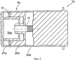
фиг.2 - усовершенствованный по сравнению с гидростатическим приводом по фиг.1 гидростатический привод с кольцевым поршнем, в разрезе;figure 2 - improved in comparison with the hydrostatic drive of figure 1 hydrostatic drive with an annular piston, in section;
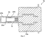
фиг.3 - усовершенствованный по сравнению с гидростатическим приводом по фиг.1 гидростатический привод с нераздельным унифицированным узлом из корпуса подающего цилиндра и втулки планетарной обкатной передачи;figure 3 - improved in comparison with the hydrostatic drive of figure 1, a hydrostatic drive with an inseparable unified node from the body of the feed cylinder and the planetary gearbox sleeve;
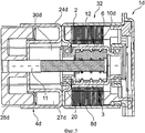
фиг.4 - усовершенствованный по сравнению с гидростатическим приводом по фиг.1 гидростатический привод с интегрированной доливочной емкостью, в частичном разрезе;figure 4 is improved in comparison with the hydrostatic drive of figure 1 hydrostatic drive with integrated top-up capacity, in partial section;
фиг.5 - гидростатический привод с перемещаемым планетарной обкатной передачей поршнем, в разрезе;5 is a sectional view of a hydrostatic drive with a movable planetary round-trip gear piston;
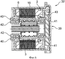
фиг.6 - электромотор гидростатического привода с различными возможностями компоновки сенсорного устройства, в разрезе;6 is an electric motor hydrostatic drive with various layout options of the sensor device, in the context;
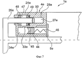
фиг.7 - усовершенствованный по сравнению с гидростатическим приводом по фиг.2 гидростатический привод с расположенной радиально внутри камеры сжатия доливочной емкостью, вид в частичном разрезе.FIG. 7 is a hydrostatic drive improved in comparison with the hydrostatic drive of FIG. 2 with a filling tank located radially inside the compression chamber, a partial sectional view.
На фиг.1 показан в разрезе гидростатический привод 1, например гидростатический привод сцепления с электромотором 2, планетарной обкатной передачей 3 и подающим цилиндром 4, расположенными вокруг оси 5 вращения ротора 6 электромотора 2. Статор 7 электромотора неподвижно соединен в корпусе 8 с крышкой 9. Ротор 6 вмещает радиально внутри планетарную обкатную передачу 3, образованную втулкой 10, шпинделем 11 передачи и перекатывающимися между ними, распределенными по окружности и фиксированными во втулке 10 с возможностью поворота планетарными телами 12 качения. Для повышения передаточного отношения планетарные тела 12 качения имеют грубое зубчатое зацепление 13, входящее в зацепление с внутренним зубчатым зацеплением 14 втулки 10, и участки 15 мелкой резьбы, перекатывающиеся по наружной резьбе 16 шпинделя 11 передачи. В отношении функционирования планетарной обкатной передачи 3 рекомендуется обратиться к документам ЕР 0320621 А1 и DE 19540634 С1.Figure 1 shows in section a hydrostatic drive 1, for example a hydrostatic clutch drive with an
В показанном варианте выполнения планетарная обкатная передача 3 установлена в роторе 6 соосно к нему, причем функционально шпиндель 11 передачи перемещается по оси при повороте ротора 6. При этом втулка 10 неподвижно соединена с ротором 6. Ротор 6 обычно может быть выполнен из конструкции из листа металла с постоянными магнитами 17, причем конструкция из листа металла неподвижно соединена со втулкой 10, например, при приваривании или запрессовке. Альтернативно постоянные магниты 17 могут быть установлены на втулке 10 по отдельности, например приклеены к ней, так что экономится соответствующее конструктивное пространство для конструкции из листа металла. Втулка 10 обеспечивает как установку планетарной обкатной передачи 3, так и ротора 6 относительно корпуса 8. Для этого предпочтительно образованная из листа металла втулка 10 имеет два осевых выступа 18, 19, на которые установлен соответственно подшипник 20, 21 качения. Подшипник 20 качения неподвижно установлен по оси в участке 22 корпуса 8, подшипник 21 качения несет центрированный в корпусе 8 вкладыш 23. Монтаж ротора 6 с планетарной обкатной передачей 3 осуществляют с открытой стороны корпуса 8, закрываемой после установки ротора 6 посредством крышки 9.In the shown embodiment, the planetary
Подающий цилиндр 4 неподвижно соединен посредством своего, предпочтительно, образованного листом металла корпуса 24 с корпусом 8 электромотора, например приварен. Центрирование корпуса 24 относительно корпуса 8 может осуществляться, например, в центровочном буртике 25. Поршень 26 образует с корпусом 24 камеру 27 сжатия, которая может быть снабжена для соединения к напорному трубопроводу посредством напорного патрубка 28, соединенного с напорным трубопроводом, причем напорный трубопровод 28 показан на чертеже только в виде отверстия, в соответствии с желаемым видом соединения: быстроразъемной муфтой, винтовым соединением или им подобными. Вследствие создаваемого при перемещении поршня 26 давления в камере 27 сжатия, предпочтительно, наполненной жидкой рабочей средой, приводится в действие присоединенный к другой стороне напорного трубопровода рабочий цилиндр, действующий на тарельчатую пружину, рычажную пружину или другое средство нагрузки фрикционной передачи, нажимающее или зажимающее в зависимости от варианта выполнения, как принудительно открытая или закрытая фрикционная передача.The supply cylinder 4 is fixedly connected by means of its preferably formed by the sheet of metal of the housing 24 with the housing 8 of the electric motor, for example, welded. The centering of the housing 24 relative to the housing 8 can be carried out, for example, in the centering shoulder 25. The piston 26 forms a compression chamber 27 with the housing 24, which can be provided for connection to the pressure pipe by means of a pressure pipe 28 connected to the pressure pipe, and pressure pipe 28 is shown in the drawing, only in the form of an opening, in accordance with the desired type of connection: quick coupler, screw connection or the like. Due to the pressure created during the movement of the piston 26 in the compression chamber 27, preferably filled with a liquid working medium, a working cylinder connected to the other side of the pressure pipe acts on a disk spring, lever spring or other friction gear loading means, pressing or clamping depending from an embodiment as a forced open or closed friction gear.
Камера сжатия 27 закрывается на отвернутой от электромотора 2 стороне поршня 26, поэтому она нагружается давлением при движении смещения поршня 26. Подвод давления происходит при осевом перемещении шпинделя 11 с винтовой резьбой, принимающего поршень 26 в осевой направляющей 29. При этом шпиндель 11 передачи неподвижно соединен по оси с поршнем 26. Камера 27 сжатия может быть соединена в разгруженном положении с не изображенной на чертеже доливочной емкостью, которая может быть интегрирована в остающееся свободным, например в изображенное пунктиром при разгруженной камере 27 сжатия, свободное пространство 30 между поршнем и корпусом 24. На чертеже не изображено соответствующее соединение, например, разъединяемое поршнем 26 в оттянутом положении и замыкаемое при сжатии камеры 27 сжатия при осевом перемещении поршня 26.The compression chamber 27 is closed on the side of the piston 26, which is turned away from the
На фиг.2 показан измененный по сравнению с гидростатическим приводом 1 по фиг.1 в отношении выполнения подающего цилиндра 4а гидростатический привод 1а в разрезе, причем электромотор с планетарной обкатной передачей в деталях не изображен и, по существу, соответствует электромотору 2 с планетарной обкатной передачей 3 по фиг.1. В показанном варианте выполнения корпус 24а подающего цилиндра 4а образует кольцеобразную камеру 27а сжатия, ограниченную соответственно выполненной кольцеобразно поверхностью 31 поршня 26а. Камера 27а сжатия расположена в соответствии с камерой 27 сжатия по фиг.1 на отвернутой от электромотора стороне, поэтому приведение в движение поршня 26а происходит в направлении смещения шпинделя 11 с винтовой резьбой. Доливочная емкость может быть предусмотрена в свободном пространстве 30а радиально внутри камеры 27а сжатия.FIG. 2 shows a sectional view of a
На фиг.3 показан частичный разрез гидростатического привода 1b, при изменении которого в отличие от гидростатического привода 1, 1а по фиг.1 и по фиг.2 втулка 10а не изображенной планетарной обкатной передачи и корпус 24b подающего цилиндра 4b изготовлены неразъемно, предпочтительно, из листа металла, например, посредством способа глубокой вытяжки. На торцевом конце корпуса 24b выполнена ограниченная поршнем 26b камера сжатия 27b. Поршень 26b может быть непосредственно приформован к шпинделю 11 передачи или соединен с ним. Данная разница передаточного числа между поршнем 26b и шпинделем 11 передачи выравнивается динамическим уплотнением, например уплотнением с уплотнительной манжетой. Альтернативно или дополнительно между поршнем и шпинделями передачи гидростатических приводов может быть предусмотрено неподвижное по оси, однако с возможностью поворота соединение. Кроме того шпиндель передачи может быть расположен со стопорением от прокручивания на неподвижном элементе корпуса, например, на корпусе 24b.Figure 3 shows a partial section of the
На фиг.4 показан частичный разрез выше оси 5 вращения гидростатического привода 1с, в котором конструкция подающего цилиндра 4с изменена по сравнению с гидростатическими приводами 1, 1a, 1b по фиг.1-3. В показанном гидростатическом приводе 1с образованная поршнем 26с и корпусом 24с камера сжатия 27с с напорным патрубком 28с расположена по оси между поршнем 26с и образованным электромотором и планетарной обкатной передачей конструктивным узлом 32, так что в нем создается давление при перемещении по оси поршня 26с шпинделем 11 передачи в направлении конструктивного узла 32. В соответствии с этим давление создается в направлении протягивания поршня 26с, поэтому подающий цилиндр 4с протягивается против конструктивного узла 32, чем можно достигать преимуществ в отношении статического расчета гидростатического привода 1с. Доливочная емкость 33 интегрирована в корпус 24с и предусмотрена радиально снаружи камеры 27с сжатия. В разгруженном положении камеры 27с сжатия объем доливочной емкости 33 соединен через доливочное отверстие 34 в виде продувочного сверления, так что может происходить уравновешивание рабочей среды, а при необходимости - отправление в доливочную емкость 33 подмешанных из рабочего цилиндра и напорного трубопровода в камеру 27с сжатия воздушных пузырьков. Доливочная емкость 33 заполняется через заливное отверстие 35, которое, как, например, показано на чертеже, закрыто шариком 36. Выравнивание давления доливочной емкости 33 происходит посредством только схематически представленной мембраны 37, которая может быть также выполнена в виде сильфона с осевой складчатостью. Избыточное давление доливочной емкости 33 может уравновешиваться при необходимости посредством не изображенного герметичного отверстия, такого как лабиринтное отверстие и/или мембранное отверстие. Предусмотренное в корпусе 24с для образования камеры сжатия отверстие 38 снабжено, в частности, закрывающей пластиной в виде мембраны или сильфона для предотвращения заноса грязи.Figure 4 shows a partial section above the axis of
На фиг.5 показан альтернативный вариант выполнения в разрезе гидростатического привода 1d по сравнению с гидростатическим приводом 1с по фиг.4. В нем конструктивный узел 32, по существу, идентичен конструктивному узлу по фиг.1, образованному из электромотора 2 и планетарной обкатной передачи 3. Вследствие приведения в движение поршня 26d в направлении движения натягивания шпинделя 11 передачи может создаваться осевая опора планетарной обкатной передачи 3 против действующего на камеру 27d сжатия усилия нажима со стороны корпуса, например, при опоре на корпус 24d подающего цилиндра 4d, так что силовой поток не проходит через электромотор 2. При этом в показанном варианте выполнения при подводе давления к камере 27d сжатия поршнем 26d неподвижно соединенная с ротором 6 втулка 10d затягивается посредством подшипника 20 качения против упора корпуса 8d, неподвижно соединенного с корпусом 24d подающего цилиндра, так что силовой поток замыкается от втулки 10d, через планетарные тела 12 качения и шпиндель 11 с винтовой резьбой в поршень 26d, а оттуда - через корпус 24d, корпус 8d, через подшипник 20 качения - к втулке 10d. В свободном пространстве 30d радиально внутри камеры 27d сжатия может быть размещена не изображенная доливочная емкость.Figure 5 shows an alternative embodiment in section of a
На фиг.6 показан конструктивный узел 32 гидростатического привода с электромотором 2 и планетарной обкатной передачей 3, а также возможная компоновка сенсорного устройства 39 для регистрации числа оборотов ротора 6 или втулки 10. На изображении показаны два варианта позиционирования датчиков 40 и 41. Датчики 40, 41 могут быть выполнены в виде датчиков Холла, причем при необходимости эти сенсорные магниты 42 могут быть расположены на противоположном к ним конструктивном элементе с возможностью вращения. Датчики 40, 41 могут приводиться в действие активно или пассивно, между датчиками 40, 41 и не изображенным блоком управления может быть предусмотрен предварительный электронный блок 43, который формирует, например, низкоомные и стандартизованные данные из исходных данных, полученных от датчиков 40, 41, и передает их дальше в блок управления. При помощи полученных данных можно коммутировать выполненный как бесщеточный двигатель электромотор 2 и/или определять посредством известного передаточного отношения планетарной обкатной передачи 3 осевой ход поршня. Кроме того, сенсорное устройство 39 в случае не проскальзывающего выполнения планетарной обкатной передачи 3 может распознавать скольжение, обрабатывать его в блоке управления и компенсировать. Кроме того, сенсорное устройство 39 может содержать датчик давления определения давления в камере сжатия подающего цилиндра. В частных случаях можно предусматривать систему измерения перемещения поршня.6 shows a
На фиг.7 показан изображенный выше оси 5 вращения схематичный частичный разрез гидростатического привода 1e, похожего на гидростатический привод 1d по фиг.5. В отличие от него подающий цилиндр 4е снабжен расположенной радиально внутри образованной поршнем 26е и корпусом 24е камеры 27е сжатия с напорным патрубком 28е доливочной емкостью 33е. Доливочная емкость 33е расположена гидростатически ниже камеры 27е сжатия, поэтому доливочная емкость 33е предварительно напряжена для обеспечения при необходимости требуемого доливания в камеру сжатия. Для этого объем доливочной емкости предварительно напрягают поршнем 44, снабженным уплотнением 45, причем между поршнем 44 и корпусом 24е и соответственно соединенным с ним корпусом 8е электромотора зажат накопитель 46 энергии, например, в виде пружины сжатия или подобного элемента. Через доливочное отверстие 34е доливаемая рабочая среда поступает в участок 47 уплотнения корпуса 24е, в то время как поршень 26е, с одной стороны, уплотняется наружу посредством уплотнения в виде кольцевого уплотнения 48, а с другой стороны, относительно камеры 27е сжатия - посредством уплотнения, в виде кольцевого уплотнения 49. При перемещении поршня 26е в разгруженное от давления положение подающего цилиндра предусмотренные в поршне 26е продувочные пазы 50 выходят за пределы кольцевого уплотнения 49 и разблокируют соединение между доливочной емкостью 33е и камерой 27е сжатия, посредством которой при необходимости может происходить обмен рабочей среды.FIG. 7 shows a schematic partial section of the
Claims (15)
Applications Claiming Priority (5)
| Application Number | Priority Date | Filing Date | Title |
|---|---|---|---|
| DE102009051244 | 2009-10-29 | ||
| DE102009051244.6 | 2009-10-29 | ||
| DE102010009297 | 2010-02-25 | ||
| DE102010009297.5 | 2010-02-25 | ||
| PCT/DE2010/001183 WO2011050766A1 (en) | 2009-10-29 | 2010-10-07 | Hydrostatic clutch actuator |
Publications (2)
| Publication Number | Publication Date |
|---|---|
| RU2012122060A RU2012122060A (en) | 2013-12-10 |
| RU2570244C2 true RU2570244C2 (en) | 2015-12-10 |
Family
ID=43531005
Family Applications (1)
| Application Number | Title | Priority Date | Filing Date |
|---|---|---|---|
| RU2012122060/11A RU2570244C2 (en) | 2009-10-29 | 2010-10-07 | Clutch hydrostatic drive |
Country Status (8)
| Country | Link |
|---|---|
| US (1) | US9051974B2 (en) |
| EP (1) | EP2494228B1 (en) |
| JP (1) | JP5734303B2 (en) |
| KR (1) | KR101798250B1 (en) |
| CN (1) | CN102575730B (en) |
| DE (2) | DE102010047800A1 (en) |
| RU (1) | RU2570244C2 (en) |
| WO (1) | WO2011050766A1 (en) |
Cited By (1)
| Publication number | Priority date | Publication date | Assignee | Title |
|---|---|---|---|---|
| RU2802704C2 (en) * | 2022-02-21 | 2023-08-31 | Сергей Леонидович Заярный | Friction hydrostatic clutch |
Families Citing this family (105)
| Publication number | Priority date | Publication date | Assignee | Title |
|---|---|---|---|---|
| DE102011014932A1 (en) | 2010-04-12 | 2011-10-13 | Schaeffler Technologies Gmbh & Co. Kg | Hydrostataktor and arrangement of a Hydrostataktors in a motor vehicle |
| WO2012000483A1 (en) | 2010-06-29 | 2012-01-05 | Schaeffler Technologies Gmbh & Co. Kg | Hydrostatic actuator |
| DE102012204940A1 (en) | 2011-04-15 | 2012-10-18 | Schaeffler Technologies AG & Co. KG | Method for adapting parameters of a coupling |
| CN103477108B (en) | 2011-04-15 | 2017-05-10 | 舍弗勒技术股份两合公司 | Method for putting a clutch into operation |
| DE102012206306A1 (en) | 2011-05-05 | 2012-11-08 | Schaeffler Technologies AG & Co. KG | Actuating device for a double clutch |
| DE102011083329A1 (en) | 2011-09-23 | 2013-03-28 | Schaeffler Technologies AG & Co. KG | Device for compensation of plucking oscillations of friction clutch in motor car, has acceleration sensor for detecting plucking oscillations of clutch, where electronic unit and actuator partially compensates oscillations of clutch |
| DE102011085127A1 (en) | 2011-10-24 | 2013-04-25 | Schaeffler Technologies AG & Co. KG | Device for operating dual clutch e.g. wet dual clutch, in power train of motor car, has pressure relief valve designed as spring force actuated check valve for limiting maximum pressure value to predetermined level |
| DE102011085129A1 (en) | 2011-10-24 | 2013-04-25 | Schaeffler Technologies AG & Co. KG | Device for e.g. start-up of vehicle transmission with gear box actuator in dual-clutch transmission system of motor vehicle, has clutch actuators controlled by computer so that gear box and clutch start-ups are implemented independently |
| DE102012218252B4 (en) | 2011-10-24 | 2023-11-02 | Schaeffler Technologies AG & Co. KG | Method for starting up a vehicle transmission and/or a vehicle clutch |
| JP6238902B2 (en) | 2011-11-24 | 2017-11-29 | シェフラー テクノロジーズ アー・ゲー ウント コー. カー・ゲーSchaeffler Technologies AG & Co. KG | Method for checking proper filling of hydraulic operating device |
| DE102012220179B4 (en) | 2011-11-24 | 2024-05-02 | Schaeffler Technologies AG & Co. KG | Procedure for checking correct filling of a hydraulic clutch system |
| DE102011088995A1 (en) * | 2011-12-19 | 2013-06-20 | Schaeffler Technologies AG & Co. KG | Planetenwälzgewindetrieb |
| DE102012220177B4 (en) | 2012-01-03 | 2024-05-08 | Schaeffler Technologies AG & Co. KG | Procedure for checking correct filling of a hydraulic actuation system |
| DE102012220178B4 (en) | 2012-01-26 | 2022-02-10 | Schaeffler Technologies AG & Co. KG | Procedure for fault detection in a hydraulic clutch control system |
| DE102013201933A1 (en) | 2012-02-22 | 2013-08-22 | Schaeffler Technologies AG & Co. KG | Method for checking software compatibility of control devices, involves completing review as correct, if software version identifiers of checked control devices are valid and equal, and/or both are considered as valid |
| CN104067017B (en) | 2012-02-22 | 2016-08-24 | 舍弗勒技术股份两合公司 | Method for determining and/or compensating for crosstalk characteristics of a dual clutch transmission |
| DE102013202700A1 (en) | 2012-03-12 | 2013-09-12 | Schaeffler Technologies AG & Co. KG | Planetary roller gearbox for use classical spindle drive in hydrostatic actuator, has planetary carrier rotationally blocked with respect to spindle nut by locking device, and planetary rolling elements arranged at planetary carrier |
| DE102012203813A1 (en) | 2012-03-12 | 2013-09-12 | Schaeffler Technologies AG & Co. KG | Method for operating of actuating system e.g. dual clutch actuating system of motor car, involves reading operational parameters stored in non-volatile memories of main control apparatus and actuators from non-volatile memories |
| WO2013156269A1 (en) | 2012-04-16 | 2013-10-24 | Schaeffler Technologies AG & Co. KG | Actuator system for hydraulic clutch actuation |
| DE102013207263A1 (en) | 2012-05-08 | 2013-11-14 | Schaeffler Technologies AG & Co. KG | Method for adjusting clutch characteristic curve of automatically actuated friction clutch, involves determining touch point change of friction clutch in operating phases before pressure- or volume compensation |
| DE112013003240B4 (en) | 2012-06-26 | 2024-04-11 | Schaeffler Technologies AG & Co. KG | Method for controlling a motor vehicle transmission |
| DE102012212282B4 (en) | 2012-07-13 | 2021-12-02 | Schaeffler Technologies AG & Co. KG | Method for braking a motor vehicle with a dual clutch transmission |
| DE112013003567B4 (en) | 2012-07-17 | 2022-02-03 | Schaeffler Technologies AG & Co. KG | Method for determining parameters of a friction clutch device |
| FR2993949B1 (en) * | 2012-07-25 | 2015-05-15 | Renault Sa | ELECTRO-HYDRAULIC CLUTCH CONTROL DEVICE FOR AUTOMATED GEARBOX |
| DE102013215076A1 (en) * | 2012-08-02 | 2014-02-06 | Schaeffler Technologies AG & Co. KG | Piston-cylinder unit of a hydraulic system |
| CN104685249B (en) * | 2012-09-26 | 2018-09-14 | 舍弗勒技术股份两合公司 | Release system for a clutch of a motor vehicle |
| DE102012220076A1 (en) | 2012-11-05 | 2014-05-08 | Schaeffler Technologies Gmbh & Co. Kg | Method for determining failure of pressure sensor in hydrostatic clutch actuator used in motor vehicle, involves detecting failure of sensor by comparing measured value of sensor signal with reference value |
| DE102012223765A1 (en) | 2012-12-19 | 2014-06-26 | Schaeffler Technologies Gmbh & Co. Kg | Method for stabilizing a coefficient of friction gradient of a clutch in a motor vehicle |
| DE102014201791A1 (en) | 2013-02-27 | 2014-08-28 | Schaeffler Technologies Gmbh & Co. Kg | Hydraulic fact actuator for automated operation of a friction clutch used in powertrain of motor car, changes rotating movement of rotor of electromotor corresponding to linear shift movement of piston and rotation speed of rotor |
| DE102014203219B4 (en) | 2013-03-18 | 2022-09-15 | Schaeffler Technologies AG & Co. KG | Method for determining a pilot voltage of an electric motor in a hydrostatically actuated clutch system in an automated manual transmission of a motor vehicle |
| DE102014208088A1 (en) | 2013-05-07 | 2014-11-13 | Schaeffler Technologies Gmbh & Co. Kg | Hydrostatic clutch actuator and method for determining the position of a target for a position sensor |
| DE102013213888B3 (en) * | 2013-07-16 | 2014-11-13 | Robert Bosch Gmbh | Electrohydraulic actuator |
| DE102014213621A1 (en) | 2013-08-09 | 2015-02-12 | Schaeffler Technologies Gmbh & Co. Kg | Method for positioning a piston |
| KR102267897B1 (en) | 2013-10-01 | 2021-06-23 | 섀플러 테크놀로지스 아게 운트 코. 카게 | Assembly with friction arrangement |
| DE102014218895A1 (en) | 2013-10-04 | 2015-04-09 | Schaeffler Technologies Gmbh & Co. Kg | clutch maintenance |
| DE102014220728A1 (en) | 2013-10-28 | 2015-05-21 | Schaeffler Technologies Gmbh & Co. Kg | Actuating device with spindle drive and rotary position sensor |
| CN105705818A (en) | 2013-11-05 | 2016-06-22 | 舍弗勒技术股份两合公司 | hydraulic assembly |
| CN105683605B (en) | 2013-11-18 | 2017-12-22 | 舍弗勒技术股份两合公司 | Torque support of an actuator on a clutch housing/transmission housing |
| DE102014221090A1 (en) * | 2013-11-18 | 2015-05-21 | Schaeffler Technologies Gmbh & Co. Kg | Planetenwälzgetriebe and actuator with this |
| DE112014005410A5 (en) | 2013-11-27 | 2016-09-01 | Schaeffler Technologies AG & Co. KG | Spindle rotor unit |
| DE112014005544A5 (en) | 2013-12-06 | 2016-09-29 | Schaeffler Technologies AG & Co. KG | Actuator with a transmission that converts a rotary motion into a linear motion |
| JP6598775B2 (en) | 2013-12-06 | 2019-10-30 | シェフラー テクノロジーズ アー・ゲー ウント コー. カー・ゲー | Actuator with planetary rolling threaded spindle (PWG) |
| WO2015090316A1 (en) | 2013-12-17 | 2015-06-25 | Schaeffler Technologies AG & Co. KG | Hydrostatic actuator arrangement and method for mounting such an actuator arrangement |
| KR102291862B1 (en) * | 2014-01-23 | 2021-08-23 | 섀플러 테크놀로지스 아게 운트 코. 카게 | Hydrostatically operated clutch system |
| JP6632537B2 (en) * | 2014-02-06 | 2020-01-22 | シェフラー テクノロジーズ アー・ゲー ウント コー. カー・ゲーSchaeffler Technologies AG & Co. KG | Actuator with planetary rolling threaded spindle (PWG) |
| DE102014202249A1 (en) | 2014-02-07 | 2015-08-13 | Schaeffler Technologies AG & Co. KG | Method for controlling a motor vehicle transmission |
| CN208487010U (en) | 2014-02-28 | 2019-02-12 | 凤凰计划股份有限公司 | The integral pump of the prime mover independently driven with two |
| DE112015001089A5 (en) | 2014-03-03 | 2016-11-24 | Schaeffler Technologies AG & Co. KG | Hydrostatic system and hydrostatic actuator with this |
| DE102015202270A1 (en) | 2014-03-05 | 2015-09-10 | Schaeffler Technologies AG & Co. KG | Planetary roller screw (PWG) |
| DE112015001422A5 (en) * | 2014-03-24 | 2016-12-08 | Schaeffler Technologies AG & Co. KG | Actuator and method for its production |
| DE112015001664A5 (en) * | 2014-04-01 | 2016-12-29 | Schaeffler Technologies AG & Co. KG | Betätigungsaktuator |
| DE112015001927A5 (en) | 2014-04-24 | 2017-01-05 | Schaeffler Technologies AG & Co. KG | Actuator device for a hydraulic actuator and corresponding hydraulic actuator |
| DE102014216309B4 (en) | 2014-08-18 | 2020-09-24 | Schaeffler Technologies AG & Co. KG | Method for local heating of a viscous elastic component of a hydrostatic actuator of a vehicle and a hydrostatic clutch actuator |
| DE102014218180B3 (en) * | 2014-09-11 | 2016-01-21 | Schaeffler Technologies AG & Co. KG | Actuator with planetary roller screw (PWG) |
| DE102015217164B4 (en) | 2014-09-11 | 2022-03-24 | Schaeffler Technologies AG & Co. KG | Assembly with a friction device |
| DE102014219361B4 (en) * | 2014-09-25 | 2016-10-06 | Schaeffler Technologies AG & Co. KG | Clutch actuation system |
| DE102015217582B4 (en) | 2014-10-01 | 2023-08-03 | Schaeffler Technologies AG & Co. KG | Hydraulic actuator for actuating a friction clutch |
| DE102014219898B4 (en) | 2014-10-01 | 2024-10-24 | Schaeffler Technologies AG & Co. KG | Actuating device of a friction clutch device with an assembly arrangement |
| DE102014220415A1 (en) | 2014-10-08 | 2016-04-14 | Schaeffler Technologies AG & Co. KG | Master cylinder |
| DE102014223479B3 (en) * | 2014-11-18 | 2016-04-07 | Schaeffler Technologies AG & Co. KG | Method for setting a stop position of a hydrostatic clutch actuator |
| DE102015220680A1 (en) | 2014-11-19 | 2016-05-19 | Schaeffler Technologies AG & Co. KG | Assembly with a friction device |
| DE102014225590A1 (en) | 2014-12-11 | 2016-06-16 | Robert Bosch Gmbh | Piston assembly for a pressure generating device, pressure generating device, hydraulic unit for interacting with the pressure generating device, brake system and method for mounting the piston assembly for the pressure generating device |
| DE102015220920B4 (en) | 2014-12-15 | 2023-02-16 | Schaeffler Technologies AG & Co. KG | Assembly with a friction device |
| DE102015200611A1 (en) | 2015-01-16 | 2016-07-21 | Schaeffler Technologies AG & Co. KG | Planetary roller screw drive (PWG) |
| DE102015223423A1 (en) | 2015-01-19 | 2016-07-21 | Schaeffler Technologies AG & Co. KG | Planetary roller screw drive (PWG) of an actuator |
| DE102015201600A1 (en) | 2015-01-30 | 2016-08-04 | Schaeffler Technologies AG & Co. KG | Actuator with planetary roller screw |
| DE102015202827B3 (en) | 2015-02-17 | 2016-04-28 | Schaeffler Technologies AG & Co. KG | Actuator with planetary roller screw drive |
| DE102015204504B4 (en) | 2015-03-12 | 2018-05-17 | Schaeffler Technologies AG & Co. KG | Assembly, in particular actuator with a friction device |
| DE102015204588B4 (en) | 2015-03-13 | 2021-10-28 | Schaeffler Technologies AG & Co. KG | Actuator with a friction device using a wrap spring element and method for producing the wrap spring element |
| DE102015204587B4 (en) | 2015-03-13 | 2016-11-10 | Schaeffler Technologies AG & Co. KG | Planetary roller screw (PWG) |
| DE102015205717B4 (en) | 2015-03-30 | 2016-11-10 | Schaeffler Technologies AG & Co. KG | Actuator with a planetary roller screw drive (PWG) |
| DE102015205889A1 (en) | 2015-04-01 | 2016-10-06 | Schaeffler Technologies AG & Co. KG | Planetary roller screw drive (PWG) and actuator with a planetary roller screw drive |
| DE102015205963B3 (en) | 2015-04-01 | 2016-05-19 | Schaeffler Technologies AG & Co. KG | Planetary roller screw drive (PWG) and actuator with a planetary roller screw drive |
| DE102015206735B3 (en) * | 2015-04-15 | 2016-05-19 | Schaeffler Technologies AG & Co. KG | Actuator with planetary roller screw drive |
| DE102015207082B4 (en) | 2015-04-20 | 2017-07-06 | Schaeffler Technologies AG & Co. KG | Actuator with a friction device using a wrap spring element |
| DE102015207642B4 (en) * | 2015-04-27 | 2017-07-06 | Schaeffler Technologies AG & Co. KG | Actuator with planetary roller screw drive |
| DE102016210190A1 (en) | 2015-06-09 | 2016-12-15 | Schaeffler Technologies AG & Co. KG | Actuator with planetary roller screw |
| DE102015212643A1 (en) | 2015-07-07 | 2017-01-12 | Schaeffler Technologies AG & Co. KG | screw |
| DE102015214246B4 (en) * | 2015-07-28 | 2021-09-16 | Schaeffler Technologies AG & Co. KG | Linear actuator arrangement for actuating a mechanical unit, preferably for actuating a clutch |
| DE102015214435B4 (en) | 2015-07-30 | 2024-03-21 | Schaeffler Technologies AG & Co. KG | Absolute position measuring device for a spindle actuator of a hydraulic encoder unit |
| DE102015214976A1 (en) | 2015-08-06 | 2017-02-09 | Schaeffler Technologies AG & Co. KG | Hydrostatic clutch actuator for operating a friction clutch |
| DE102015215525A1 (en) | 2015-08-14 | 2017-03-09 | Schaeffler Technologies AG & Co. KG | A method for avoiding the operation of a first computer program and a second computer program on a computer |
| DE102015216371B4 (en) | 2015-08-27 | 2021-10-07 | Schaeffler Technologies AG & Co. KG | Plastic housing with an ultrasonic welded connection, in particular for a hydrostatic actuator and hydrostatic actuator with this |
| DE102015216509A1 (en) * | 2015-08-28 | 2017-03-02 | Schaeffler Technologies AG & Co. KG | Angle measuring device for a rotary driven linear actuator |
| JP6938483B2 (en) | 2015-10-08 | 2021-09-22 | シェフラー テクノロジーズ アー・ゲー ウント コー. カー・ゲーSchaeffler Technologies AG & Co. KG | Friction clutch control method |
| DE102015221556A1 (en) | 2015-11-04 | 2017-05-04 | Schaeffler Technologies AG & Co. KG | Planetary roller screw (PWG) of an actuator |
| DE102016222070A1 (en) | 2015-11-12 | 2017-05-18 | Schaeffler Technologies AG & Co. KG | actuator device |
| DE102016222863A1 (en) | 2015-11-25 | 2017-06-01 | Schaeffler Technologies AG & Co. KG | Absolutwegmesseinrichtung for a Spindelaktor a Betätigungsaktors |
| DE102015224662A1 (en) | 2015-12-09 | 2017-06-14 | Schaeffler Technologies AG & Co. KG | Actuator with planetary roller screw drive (PWG) |
| CN105402273B (en) * | 2015-12-22 | 2017-09-12 | 武汉理工通宇新源动力有限公司 | A kind of motor driven liquid pressure clutch and automobile |
| EP3210717B1 (en) * | 2016-02-24 | 2020-10-14 | Admede Ab | System for supplying hydraulic pressure to a bolt elongation tool |
| US10413272B2 (en) | 2016-03-08 | 2019-09-17 | Covidien Lp | Surgical tool with flex circuit ultrasound sensor |
| EP3501087B1 (en) * | 2016-08-17 | 2022-11-23 | Project Phoenix LLC | Motor operated accumulator |
| DE102016222981A1 (en) | 2016-11-22 | 2018-05-24 | Schaeffler Technologies AG & Co. KG | Actuator for actuating a clutch |
| WO2018213367A1 (en) * | 2017-05-17 | 2018-11-22 | Kinetic Pressure Control, Ltd. | Rotary drive actuator for an annular wellbore pressure control device |
| US10711871B2 (en) * | 2018-01-26 | 2020-07-14 | Schaeffler Technologies AG & Co. KG | Axially compact linear actuator drive arrangement |
| DE102018202709B3 (en) | 2018-02-22 | 2019-05-16 | Magna Powertrain Bad Homburg GmbH | Electrohydraulic actuator |
| DE102018106174A1 (en) | 2018-03-16 | 2019-09-19 | Schaeffler Technologies AG & Co. KG | Method for controlling a clutch actuator |
| DE102018115592A1 (en) | 2018-06-28 | 2020-01-02 | Schaeffler Technologies AG & Co. KG | Method for controlling an electrohydraulic actuator |
| CN108583543A (en) * | 2018-07-02 | 2018-09-28 | 芜湖伯特利汽车安全系统股份有限公司 | A kind of executing agency applied to vehicle line control brake system |
| DE102018117341A1 (en) | 2018-07-18 | 2020-01-23 | Schaeffler Technologies AG & Co. KG | Method for operating a hydrostatic actuator system |
| AT522208A1 (en) * | 2019-03-13 | 2020-09-15 | Melecs Ews Gmbh | Electric machine |
| CN110566611A (en) * | 2019-08-30 | 2019-12-13 | 贵州新安航空机械有限责任公司 | Brake actuating cylinder piston assembly with one-way valve |
| EP4239865A4 (en) * | 2020-10-28 | 2024-10-30 | Amotech Co Ltd | Driving motor having bldc motor and swivel actuator using same |
| US11608864B2 (en) | 2021-03-31 | 2023-03-21 | Dana Italia S.R.L. | Hydraulic system and piston filling control |
Citations (4)
| Publication number | Priority date | Publication date | Assignee | Title |
|---|---|---|---|---|
| US5577433A (en) * | 1995-09-06 | 1996-11-26 | Henry; Michael F. | Regulated speed linear actuator |
| US20070068399A1 (en) * | 2005-09-26 | 2007-03-29 | Unico, Inc. | Pneumatic biasing of a linear actuator and implementations thereof |
| WO2008009547A1 (en) * | 2006-07-15 | 2008-01-24 | Zf Friedrichshafen Ag | Kupplungssteller zur automatischen betätigung einer reibungskupplung |
| US7574952B2 (en) * | 2004-02-20 | 2009-08-18 | Schunk Gmbh & Co. Kg Spann- Und Greiftechnik | Motor fluid drive, especially for rotary, pivotal or linear drive units and corresponding method |
Family Cites Families (19)
| Publication number | Priority date | Publication date | Assignee | Title |
|---|---|---|---|---|
| IT207929Z2 (en) * | 1986-02-21 | 1988-02-22 | Roltra Spa | SERVO-ASSISTED BRAKE SYSTEM FOR VEHICLES |
| DE3739059A1 (en) | 1987-11-17 | 1989-05-24 | Deutsche Forsch Luft Raumfahrt | DEVICE FOR CONVERTING A ROTATIONAL MOVEMENT INTO AN AXIAL MOVEMENT |
| US4893473A (en) * | 1988-01-21 | 1990-01-16 | Lucas Industries Public Limited Company | Reservoir-formed shoulder stop for makeup fluid valve actuation in pull-type master cylinder |
| US4924673A (en) * | 1988-02-17 | 1990-05-15 | Automotive Products Plc | Master cylinder with parallel-bore reservoir |
| FR2657400B1 (en) * | 1990-01-24 | 1994-07-01 | Automotive Prod France | HYDRAULIC MASTER CYLINDER. |
| JPH07164905A (en) * | 1993-12-14 | 1995-06-27 | Nabco Ltd | Driving force distribution control device for four-wheel drive vehicle |
| DE19540634C1 (en) | 1995-10-31 | 1997-03-13 | Deutsche Forsch Luft Raumfahrt | Mechanism converting rotary movement to axial |
| DE19700935A1 (en) | 1996-01-31 | 1997-08-07 | Luk Getriebe Systeme Gmbh | Operating apparatus for constituents of power train in motor vehicle |
| EP0922167A4 (en) * | 1996-08-30 | 2004-04-14 | Kelsey Hayes Co | Electrically actuated hydraulic power cylinder |
| US6102828A (en) * | 1998-06-03 | 2000-08-15 | Halliburton Energy Services, Inc. | Electrohydraulic control unit |
| AU1574800A (en) * | 1998-12-03 | 2000-06-19 | Britton Price Limited | Ball screw driven pump |
| JP2003307238A (en) * | 2002-04-16 | 2003-10-31 | Hino Motors Ltd | Clutch control system |
| DE102004007153B3 (en) * | 2004-02-12 | 2005-11-03 | Ortlinghaus-Werke Gmbh | Fluidically actuated rotary drive clutch |
| US7021442B2 (en) * | 2004-03-16 | 2006-04-04 | General Motors Corporation | One-way torque transmitter with a friction actuating apparatus |
| DE502005005857D1 (en) * | 2004-06-30 | 2008-12-18 | Luk Lamellen & Kupplungsbau | A method of adjusting an incremental displacement measuring device in an actuated device of a compressed clutch and actuator |
| US8118571B2 (en) * | 2005-03-31 | 2012-02-21 | Dana Automotive Systems Group, Llc | Actuator assembly |
| JP2008025697A (en) * | 2006-07-20 | 2008-02-07 | Hino Motors Ltd | Clutch operating booster |
| DE102006047790B4 (en) * | 2006-10-06 | 2015-10-15 | Narr Beteiligungs Gmbh | Device for converting a rotational movement into an axial movement |
| JP2008185043A (en) * | 2007-01-26 | 2008-08-14 | Toyota Motor Corp | Linear actuator |
-
2010
- 2010-10-07 CN CN201080045709.3A patent/CN102575730B/en active Active
- 2010-10-07 EP EP10786985.1A patent/EP2494228B1/en active Active
- 2010-10-07 JP JP2012535622A patent/JP5734303B2/en active Active
- 2010-10-07 DE DE102010047800A patent/DE102010047800A1/en not_active Withdrawn
- 2010-10-07 KR KR1020127010845A patent/KR101798250B1/en active IP Right Grant
- 2010-10-07 WO PCT/DE2010/001183 patent/WO2011050766A1/en active Application Filing
- 2010-10-07 DE DE112010004220T patent/DE112010004220A5/en not_active Withdrawn
- 2010-10-07 RU RU2012122060/11A patent/RU2570244C2/en active
-
2012
- 2012-04-26 US US13/457,000 patent/US9051974B2/en not_active Expired - Fee Related
Patent Citations (4)
| Publication number | Priority date | Publication date | Assignee | Title |
|---|---|---|---|---|
| US5577433A (en) * | 1995-09-06 | 1996-11-26 | Henry; Michael F. | Regulated speed linear actuator |
| US7574952B2 (en) * | 2004-02-20 | 2009-08-18 | Schunk Gmbh & Co. Kg Spann- Und Greiftechnik | Motor fluid drive, especially for rotary, pivotal or linear drive units and corresponding method |
| US20070068399A1 (en) * | 2005-09-26 | 2007-03-29 | Unico, Inc. | Pneumatic biasing of a linear actuator and implementations thereof |
| WO2008009547A1 (en) * | 2006-07-15 | 2008-01-24 | Zf Friedrichshafen Ag | Kupplungssteller zur automatischen betätigung einer reibungskupplung |
Cited By (1)
| Publication number | Priority date | Publication date | Assignee | Title |
|---|---|---|---|---|
| RU2802704C2 (en) * | 2022-02-21 | 2023-08-31 | Сергей Леонидович Заярный | Friction hydrostatic clutch |
Also Published As
| Publication number | Publication date |
|---|---|
| DE112010004220A5 (en) | 2012-08-30 |
| RU2012122060A (en) | 2013-12-10 |
| US9051974B2 (en) | 2015-06-09 |
| DE102010047800A1 (en) | 2011-05-05 |
| EP2494228A1 (en) | 2012-09-05 |
| US20120217117A1 (en) | 2012-08-30 |
| CN102575730B (en) | 2015-08-26 |
| JP2013509540A (en) | 2013-03-14 |
| EP2494228B1 (en) | 2014-07-02 |
| CN102575730A (en) | 2012-07-11 |
| WO2011050766A1 (en) | 2011-05-05 |
| JP5734303B2 (en) | 2015-06-17 |
| KR20120091139A (en) | 2012-08-17 |
| KR101798250B1 (en) | 2017-11-15 |
Similar Documents
| Publication | Publication Date | Title |
|---|---|---|
| RU2570244C2 (en) | Clutch hydrostatic drive | |
| RU2553618C2 (en) | Hydrostatic drive | |
| JP6243025B2 (en) | Electro-hydraulic actuator | |
| KR102379917B1 (en) | Electro-hydraulic external force pressure generator | |
| US9528563B2 (en) | Hydraulic vehicle brake with integrated electromechanically operable parking brake | |
| US6837342B1 (en) | Actuator having a central support and brake calliper comprising such actuator | |
| US20070068748A1 (en) | Combined service and auxilliary brake apparatus | |
| WO2010044416A1 (en) | Electric pump unit | |
| CN100394055C (en) | Actuating device for a clutch | |
| CN103660907A (en) | Drive unit for a motor vehicle having an electric machine and a clutch | |
| US10371275B2 (en) | Actuator having electric drive for actuating a valve device | |
| US9748040B2 (en) | Electronic control device for controlling actuators | |
| CN102084079A (en) | Linear drive for a pivotally supported panel or a pivotally supported hard or soft top of a vehicle | |
| CN110696797B (en) | Pressure generating device for a brake system of a vehicle | |
| CN113692370B (en) | Electromechanical brake pressure generator for a hydraulic brake system | |
| JP2012081799A (en) | Electric booster | |
| CN104006028B (en) | hydrostatic actuator | |
| KR102101223B1 (en) | Apparatus for regeneration and active suspension with double bi-directional pump | |
| CN109991016B (en) | Magnetorheological damping automobile roller test bed and control method thereof | |
| CN103671872A (en) | Electric control mechanical shift actuator of electric vehicle | |
| CN109855867A (en) | A kind of loading device of integrated axial load load and spin load load | |
| CN105339201A (en) | Method and device for controlling/commanding hydraulic module for hybrid vehicle |