WO2025094636A1 - 電極構造体および二次電池 - Google Patents
電極構造体および二次電池 Download PDFInfo
- Publication number
- WO2025094636A1 WO2025094636A1 PCT/JP2024/036394 JP2024036394W WO2025094636A1 WO 2025094636 A1 WO2025094636 A1 WO 2025094636A1 JP 2024036394 W JP2024036394 W JP 2024036394W WO 2025094636 A1 WO2025094636 A1 WO 2025094636A1
- Authority
- WO
- WIPO (PCT)
- Prior art keywords
- phase
- negative electrode
- layer
- amorphous
- electrode layer
- Prior art date
- Legal status (The legal status is an assumption and is not a legal conclusion. Google has not performed a legal analysis and makes no representation as to the accuracy of the status listed.)
- Pending
Links
Images









Classifications
-
- H—ELECTRICITY
- H01—ELECTRIC ELEMENTS
- H01B—CABLES; CONDUCTORS; INSULATORS; SELECTION OF MATERIALS FOR THEIR CONDUCTIVE, INSULATING OR DIELECTRIC PROPERTIES
- H01B1/00—Conductors or conductive bodies characterised by the conductive materials; Selection of materials as conductors
- H01B1/06—Conductors or conductive bodies characterised by the conductive materials; Selection of materials as conductors mainly consisting of other non-metallic substances
-
- H—ELECTRICITY
- H01—ELECTRIC ELEMENTS
- H01B—CABLES; CONDUCTORS; INSULATORS; SELECTION OF MATERIALS FOR THEIR CONDUCTIVE, INSULATING OR DIELECTRIC PROPERTIES
- H01B1/00—Conductors or conductive bodies characterised by the conductive materials; Selection of materials as conductors
- H01B1/06—Conductors or conductive bodies characterised by the conductive materials; Selection of materials as conductors mainly consisting of other non-metallic substances
- H01B1/08—Conductors or conductive bodies characterised by the conductive materials; Selection of materials as conductors mainly consisting of other non-metallic substances oxides
-
- H—ELECTRICITY
- H01—ELECTRIC ELEMENTS
- H01M—PROCESSES OR MEANS, e.g. BATTERIES, FOR THE DIRECT CONVERSION OF CHEMICAL ENERGY INTO ELECTRICAL ENERGY
- H01M10/00—Secondary cells; Manufacture thereof
- H01M10/05—Accumulators with non-aqueous electrolyte
- H01M10/052—Li-accumulators
-
- H—ELECTRICITY
- H01—ELECTRIC ELEMENTS
- H01M—PROCESSES OR MEANS, e.g. BATTERIES, FOR THE DIRECT CONVERSION OF CHEMICAL ENERGY INTO ELECTRICAL ENERGY
- H01M10/00—Secondary cells; Manufacture thereof
- H01M10/05—Accumulators with non-aqueous electrolyte
- H01M10/056—Accumulators with non-aqueous electrolyte characterised by the materials used as electrolytes, e.g. mixed inorganic/organic electrolytes
- H01M10/0561—Accumulators with non-aqueous electrolyte characterised by the materials used as electrolytes, e.g. mixed inorganic/organic electrolytes the electrolyte being constituted of inorganic materials only
- H01M10/0562—Solid materials
-
- H—ELECTRICITY
- H01—ELECTRIC ELEMENTS
- H01M—PROCESSES OR MEANS, e.g. BATTERIES, FOR THE DIRECT CONVERSION OF CHEMICAL ENERGY INTO ELECTRICAL ENERGY
- H01M4/00—Electrodes
- H01M4/02—Electrodes composed of, or comprising, active material
- H01M4/13—Electrodes for accumulators with non-aqueous electrolyte, e.g. for lithium-accumulators; Processes of manufacture thereof
-
- H—ELECTRICITY
- H01—ELECTRIC ELEMENTS
- H01M—PROCESSES OR MEANS, e.g. BATTERIES, FOR THE DIRECT CONVERSION OF CHEMICAL ENERGY INTO ELECTRICAL ENERGY
- H01M4/00—Electrodes
- H01M4/02—Electrodes composed of, or comprising, active material
- H01M4/62—Selection of inactive substances as ingredients for active masses, e.g. binders, fillers
-
- Y—GENERAL TAGGING OF NEW TECHNOLOGICAL DEVELOPMENTS; GENERAL TAGGING OF CROSS-SECTIONAL TECHNOLOGIES SPANNING OVER SEVERAL SECTIONS OF THE IPC; TECHNICAL SUBJECTS COVERED BY FORMER USPC CROSS-REFERENCE ART COLLECTIONS [XRACs] AND DIGESTS
- Y02—TECHNOLOGIES OR APPLICATIONS FOR MITIGATION OR ADAPTATION AGAINST CLIMATE CHANGE
- Y02E—REDUCTION OF GREENHOUSE GAS [GHG] EMISSIONS, RELATED TO ENERGY GENERATION, TRANSMISSION OR DISTRIBUTION
- Y02E60/00—Enabling technologies; Technologies with a potential or indirect contribution to GHG emissions mitigation
- Y02E60/10—Energy storage using batteries
Definitions
- This disclosure relates to an electrode structure and a secondary battery.
- Patent Document 1 discloses the formation of an electrode layer having a regular porous structure on a substrate made of a solid electrolyte layer.
- the present disclosure aims to improve the contact between a solid electrolyte layer and an adjacent electrode layer and reduce the interface resistance between the solid electrolyte layer and the electrode layer.
- one aspect of the present disclosure is a battery structure including a solid electrolyte layer and a pair of electrode layers disposed so as to sandwich the solid electrolyte layer.
- the solid electrolyte layer is composed of a complex of a first phase made of an oxide-based ion conductor and a second phase made of an amorphous-containing ion conductor containing at least a portion of an amorphous phase.
- the oxide-based ion conductor has a higher ionic conductivity than the amorphous-containing ion conductor.
- the amorphous-containing ion conductor has a smaller Young's modulus than the oxide-based ion conductor.
- the second phase of the amorphous-containing ionic conductor has a lower Young's modulus than the first phase and is an amorphous material, which can increase the contact area between the solid electrolyte layer and the adjacent electrode layer. This can reduce the interface resistance between the solid electrolyte layer and the adjacent electrode layer, and improve ionic conductivity.
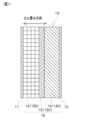
- FIG. 1 is a cross-sectional view showing a configuration of a secondary battery according to a first embodiment.
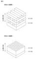
- FIG. 2 is a perspective view showing a specific example of a negative electrode structure.
- FIG. 2 is a perspective view showing a specific example of a negative electrode structure.
- FIG. 2 is a perspective view showing a specific example of a negative electrode structure.
- FIG. 2 is a diagram showing negative electrode side particles.
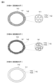
- 1A and 1B are diagrams showing specific examples of a positive electrode active material and a coating layer.
- 1A and 1B are diagrams showing specific examples of a positive electrode active material and a coating layer.
- 1A and 1B are diagrams showing specific examples of a positive electrode active material and a coating layer.
- FIG. 2 is a diagram showing a specific example of a solid electrolyte composite.
- FIG. 1 is a diagram showing the crystal structure of a pyrochlore-type oxide.
- 1 is a diagram showing a process for producing a pyrochlore type oxide.
- FIG. 1 is a SEM image of pyrochlore oxide and amorphous-containing LiF.
- 1 is a SEM image of a positive electrode active material and a coating layer.
- 11 is a flowchart showing a method for manufacturing a negative electrode structure using a stereolithography 3D printer.
- 11 is a flowchart showing a method for manufacturing a negative electrode structure using an extrusion-type 3D printer.
- 1 is a SEM image of the negative electrode structure.
- 1 is a table showing examples and comparative examples of a negative electrode structure.
- FIG. 1 is a table showing examples and comparative examples of positive electrode active materials.
- FIG. 6 is a diagram showing a negative electrode structure according to a second embodiment.
- FIG. 13 is a diagram showing a negative electrode structure according to a third embodiment.
- FIG. 13 is a diagram showing a negative electrode structure according to a fourth embodiment.
- FIG. 13 is a cross-sectional view showing the configuration of a secondary battery according to a fifth embodiment.
- FIG. 13 is a diagram showing a specific example of a solid electrolyte composite provided in a positive electrode of a fifth embodiment.
- the secondary battery 10 of this embodiment is a lithium ion battery in which lithium ions are conducted as conductive ions.
- the secondary battery 10 of this embodiment is an all-solid-state battery that uses a solid electrolyte in the solid electrolyte layer 15, and is an anode-free battery in which no negative electrode active material is provided in the negative electrode layer 12 in the initial state.
- the secondary battery 10 of this embodiment is a battery cell, and is used as a stack by connecting multiple secondary batteries 10 as necessary.
- the secondary battery 10 has as its components a negative electrode collector 11, a negative electrode layer 12, a positive electrode collector 13, a positive electrode layer 14, and a solid electrolyte layer 15. These components 11 to 15 are stacked in the cell thickness direction.
- the left-right direction in the figure is the cell thickness direction.
- the solid electrolyte layer 15 is sandwiched between a pair of electrode layers 12, 14.
- the solid electrolyte layer 15 and the pair of electrode layers 12, 14 form an electrode structure 16.
- One of the pair of electrode layers 12, 14 is an anode layer 12, and the other is a cathode layer 14.
- the anode layer 12 is provided on one surface of the solid electrolyte layer 15, and the cathode layer 14 is provided on the other surface of the solid electrolyte layer 15.
- the negative electrode layer 12 and the solid electrolyte layer 15 are in contact, and the positive electrode layer 14 and the solid electrolyte layer 15 are in contact.
- the negative electrode layer 12 and the positive electrode layer 14 are connected via the solid electrolyte layer 15.
- the secondary battery 10 is charged and discharged by the conduction of lithium ions between the negative electrode layer 12 and the positive electrode layer 14 via the solid electrolyte layer 15.
- a laminate including the negative electrode layer 12, the positive electrode layer 14, and the solid electrolyte layer 15 is provided between the negative electrode current collector 11 and the positive electrode current collector 13.
- the negative electrode current collector 11 and the negative electrode layer 12 are in contact.
- the positive electrode current collector 13 and the positive electrode layer 14 are in contact.
- the negative electrode current collector 11 and the positive electrode current collector 13 are connected via the laminate.
- the negative electrode collector 11 and the positive electrode collector 13 can be made of any material that can be used as a collector for a lithium-ion battery.
- Cu is used as the negative electrode collector 11
- Al is used as the positive electrode collector 13.
- the negative electrode layer 12 is a structure that constitutes the negative electrode, and receives lithium ions when the secondary battery 10 is charged, and releases lithium ions when the secondary battery 10 is discharged.
- the negative electrode layer 12 is an ion-conductive structure that has ion conductivity.
- the negative electrode layer 12 is configured as a porous body having a large number of pores, and the negative electrode layer 12 can be called a porous layer.
- the secondary battery 10 of this embodiment is an anode-free battery, and in the initial state, no negative electrode active material exists in the negative electrode layer 12.
- the initial state is a state in which each component of the secondary battery 10 is assembled, and the secondary battery 10 is not charged.
- elements constituting conductive ions are precipitated in the negative electrode layer 12.
- lithium ions released from the positive electrode active material are conducted from the positive electrode layer 14 to the negative electrode layer 12, and lithium metal is precipitated in the pores of the negative electrode layer 12.
- the lithium metal precipitated in the pores of the negative electrode layer 12 functions as a negative electrode active material.
- a precipitation/dissolution reaction of lithium metal as a negative electrode active material occurs in the pores of the negative electrode layer 12, and lithium ions are received or released.
- the negative electrode layer 12 has a three-dimensional structure.
- the negative electrode layer 12 can be a regular porous structure in which pores are regularly formed, or an irregular porous structure in which pores are irregularly formed.
- Regular porous structures include structures in which many pores of the same shape are formed and the pore diameter is uniform, and structures in which pores of different shapes and pore diameters are regularly arranged and the pore distribution is regular.
- Irregular porous structures include structures in which many pores of different shapes are formed and the pore diameter is nonuniform, and structures in which the pore distribution is irregular, such as when the pore diameter is uniform but the pores are randomly arranged.
- the lithium metal precipitation/dissolution reaction occurs uniformly. Therefore, the ordered porous structure of the negative electrode layer 12 can minimize the localized precipitation of lithium metal, reducing the possibility of a short circuit.
- Forms A1 to A4 in Figures 2 and 3 show specific examples of anode layer 12 with an ordered porous structure.
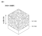
- Form A5 in Figure 4 shows a specific example of anode layer 12 with an irregular porous structure.
- the up-down direction in the figures is the cell thickness direction.
- anode current collector 11 is provided above anode layer 12.
- the regular pore structures of forms A1 to A4 and the irregular pore structure of form A5 can be manufactured, for example, using a 3D printer.
- the regular pore structures of forms A1 to A4 are obtained by regularly molding a structure having a predetermined shape, resulting in a structure with regularly formed pores.
- the irregular pore structure of form A5 is obtained by, for example, molding using a raw material mixed with a pore-forming agent, and then removing the pore-forming agent by sintering, resulting in a structure with irregularly formed pores.
- the regular porous structure of the negative electrode layer 12 can adopt various forms and is not limited to forms A1 to A4.
- the negative electrode layer 12 of form A1 multiple columnar structures are arranged in parallel.
- the negative electrode layer 12 of form A1 is formed parallel to the cell thickness direction.
- the negative electrode layer 12 of form A1 is formed linearly to connect the solid electrolyte layer 15 and the negative electrode current collector 11, and multiple columnar structures form an ion conduction path. Lithium ions are conducted inside the secondary battery 10 in the cell thickness direction. Therefore, the negative electrode layer 12 of form A1 can improve ion conductivity.
- the bending degree of the multiple columnar structures can be reduced, and ion conduction loss caused by the bending of the columnar structures and the ion conduction path becoming complicated can be reduced. As a result, ion conductivity can be improved, and the input/output performance of the secondary battery 10 can be improved.
- the negative electrode layer 12 of form A2 has a three-dimensional lattice structure, with multiple columnar structures intersecting to form a three-dimensional lattice structure.
- the negative electrode layer 12 of form A2 has structures formed in a direction perpendicular to the cell thickness direction in addition to a direction parallel to the cell thickness direction, and can have improved strength compared to the negative electrode layer 12 of form A1.
- the negative electrode layer 12 of form A3 has a parallel cross structure, and multiple layers each consisting of multiple columnar structures arranged in parallel are stacked in the cell thickness direction. In adjacent layers of columnar structures, the multiple columnar structures are arranged perpendicular to each other.
- the negative electrode layer 12 of form A3 has structures formed in a direction perpendicular to the cell thickness direction in addition to a direction parallel to the cell thickness direction, and can have improved strength compared to the negative electrode layer 12 of form A1. Furthermore, the negative electrode layer 12 of form A3 can be formed by sequentially stacking layers each consisting of multiple columnar structures arranged in parallel, and can have improved formability compared to the negative electrode layer 12 of form A2.
- the negative electrode layer 12 of form A4 has a planar lattice structure, with multiple columnar structures intersecting to form a two-dimensional lattice structure.
- the negative electrode layer 12 of form A4 also has improved strength compared to the negative electrode layer 12 of form A1.
- the negative electrode layer 12 It is desirable for the negative electrode layer 12 to have a pore diameter in the range of 0.1 to 50 ⁇ m. It is also desirable for the negative electrode layer 12 to have a molding width of the structure that forms the pores in the range of 1 to 100 ⁇ m. The molding width of the negative electrode layer 12 is the distance between adjacent pores.
- the negative electrode layer 12 mainly comprises a sintered body obtained by sintering negative electrode composite particles 120 having ion conductivity.
- the negative electrode layer 12 may contain a conductive additive and a binder.
- the negative electrode layer 12 may further contain an electrolyte and a polymer.
- the negative electrode composite particle 120 is a composite particle composed of a core phase 121 and a shell phase 122.
- the core phase 121 is formed in a particulate form, and the shell phase 122 is formed so as to cover at least a portion of the core phase 121.
- the shell phase 122 may cover the entire surface of the core phase 121, or may cover only a portion of the core phase 121.
- the core phase 121 is an oxide-based ion conductor
- the shell phase 122 is an amorphous-containing ion conductor that contains at least a portion of an amorphous phase.
- the negative electrode layer 12 is manufactured by sintering a slurry in which the negative electrode composite particles 120 are dispersed in a solvent.
- the oxide-based ion conductor of the core phase 121 reacts with the solvent in the slurry, and lithium ions, which are conductive ions, tend to dissolve from the oxide-based ion conductor.
- the shell phase 122 of the negative electrode composite particle 120 is provided to suppress the reaction between the oxide-based ion conductor of the core phase 121 and the solvent in the slurry, and to suppress the elution of lithium ions from the oxide-based ion conductor.
- the shell phase 122 of this embodiment promotes interparticle bonding during sintering, and can increase the density after sintering.
- the solid content ratio in the slurry is too low, the density of the negative electrode layer 12 after sintering will be low.
- the solid content in the slurry is too high, there is a risk that the negative electrode composite particles 120 will not be able to be slurried even if they are mixed with a solvent and stirred. For this reason, in order to reliably turn the negative electrode composite particles 120 into a slurry and to increase the density of the negative electrode layer 12 after sintering, it is desirable to set the solid content ratio in the slurry within the range of 30 to 60 vol.%.
- the negative electrode layer 12 when the negative electrode layer 12 is manufactured using a stereolithography 3D printer that irradiates a slurry with a laser, it is desirable to include a light absorbing material with a lower light transmittance than the negative electrode composite particles 120 in the slurry.
- the light absorbing material is a material with a higher absorbance than the negative electrode composite particles 120.
- a conductive assistant made of a carbon material can be used as the light absorbing material.
- the constituent material of the negative electrode layer 12 can also function as a light absorbing material, and there is no need to provide a separate light absorbing material.
- the light absorbing material contained in the slurry can prevent scattering of the laser light when the slurry is irradiated with a laser by a 3D printer. This allows the stereolithography 3D printer to achieve the desired modeling width and perform modeling with high precision.
- the constituent material of the core phase 121 and the constituent material of the shell phase 122 are ion-conductive substances with different chemical compositions.
- the constituent material of the core phase 121 has a higher ion conductivity than the constituent material of the shell phase 122.
- the volume ratio of the core phase 121 in the negative electrode composite particle 120 is set to be equal to or greater than the volume ratio of the shell phase 122.
- the core phase 121 is an oxide-based ion conductor and an oxide-based solid electrolyte.
- pyrochlore oxide, garnet oxide, etc. can be used as the core phase 121.
- Li 1.25 La 0.58 Nb 2 O 6 F (LLNOF) and Li 1.25 La 0.58 Ta 2 O 6 (LLTOF) can be used as the pyrochlore oxide.
- Li 7 La 3 Zr 2 O 12 (LLZ) can be used as the garnet oxide.
- LLNOF and LLTOF have higher ionic conductivity, lower melting point, and lower Young's modulus than LLZ.
- LLNOF and LLTOF contain less lithium in their structures than LLZ, and therefore are less likely to react with the solvent in the slurry.
- the constituent material of the shell phase 122 contains at least Li and F, and examples of the material include LiF and LiNb 6 O 15 F. In this embodiment, LiF is used as the shell phase 122.
- the constituent material of the shell phase 122 has a lower melting point than the constituent material of the core phase 121. Therefore, when manufacturing the negative electrode composite particle 120, by heating at a temperature equal to or higher than the melting point of the constituent material of the shell phase 122 and lower than the melting point of the constituent material of the core phase 121, the shell phase 122 melts, and the coverage rate of the core phase 121 by the shell phase 122 can be improved.
- the constituent material of the shell phase 122 has a lower Young's modulus than the constituent material of the core phase 121.
- the Young's modulus of Li1.25La0.58Nb2O6F used as the core phase 121 is about 100 GPa, and the Young's modulus of LiF in the crystalline phase is about 50 to 70 GPa.
- the material constituting the shell phase 122 is an amorphous-containing ion conductor that contains at least a portion of an amorphous phase.
- the material constituting the shell phase 122 may be entirely amorphous, or may contain a mixture of amorphous and crystalline phases.
- it is desirable that the volume ratio of the amorphous phase is equal to or greater than the volume ratio of the crystalline phase.
- the amorphous phase has a lower Young's modulus than the crystalline phase. Therefore, by having a high volume ratio of the amorphous phase in the shell phase 122, the contact area between the shell phase 122 and the core phase 121 can be increased, and the coverage rate of the core phase 121 by the shell phase 122 can be improved.
- the amorphous phase has an indefinite particle shape rather than a specific shape. This also makes it possible to increase the contact area between the shell phase 122 and the core phase 121, and to increase the coverage of the core phase 121 by the shell phase 122.
- the positive electrode layer 14 releases lithium ions when the secondary battery 10 is charged, and receives lithium ions when the secondary battery 10 is discharged.
- the positive electrode layer 14 contains positive electrode composite particles 140.
- the positive electrode layer 14 may contain a conductive additive and a binder.
- the positive electrode layer 14 may contain an electrolyte and a polymer in addition to the positive electrode composite particles 140.
- Figures 6 and 7 show specific examples of positive electrode composite particles 140.
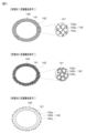
- Figure 6 shows an embodiment in which the coating layer 142 has a first phase 142a and a second phase 142b
- Figure 7 shows an embodiment in which the coating layer 142 has a first phase 142a, a second phase 142b, and a third phase 142c.
- the positive electrode composite particle 140 is a ceramic composite particle containing a positive electrode active material 141 and a coating layer 142 that covers the positive electrode active material 141.
- the positive electrode active material 141 is a ceramic particle that undergoes an oxidation-reduction reaction, and releases or receives lithium ions, which are conductive ions, through the oxidation-reduction reaction.
- the coating layer 142 has two or more phases.
- the positive electrode active material 141 for example, a layered rock salt type active material, an olivine type active material, a spinel type active material, or an acid halide type active material can be used.
- a layered rock salt type active material for example, a ternary positive electrode material such as LiNi x Mn y Co z O 2 (NMC) or LiNi x Co y Al z O 2 (NCA) can be used.
- the olivine type active material for example, LiFePO 4 (LFP), LiMn x Fe 1-x PO 4 (LMFP), LiMnPO 4 (LMP), LiCoPO 4 (LCP), or LiNiPO 4 (LNP) can be used.
- Examples of the spinel active material that can be used include LiMn 2 O 4 (LMO) and LiNi 0.5 Mn 1.5 O 4 (LNMO).
- Examples of the acid halide active material that can be used include Li 2 MnO 3-x F x .
- the coating layer 142 covers at least a portion of the positive electrode active material 141.
- the coating layer 142 is provided to prevent the positive electrode active material 141 from coming into contact with and reacting with other materials, such as the solid electrolyte of the solid electrolyte layer 15.
- the coating layer 142 contains two or more phases made of different ion conductors.
- the coating layer 142 contains a first phase 142a made of an oxide-based ion conductor, and a second phase 142b made of an amorphous-containing ion conductor that contains at least a portion of an amorphous phase.
- the coating layer 142 may cover the entire surface of the positive electrode active material 141, or may cover only a portion of the positive electrode active material 141. In order to prevent the positive electrode active material 141 from coming into contact with and reacting with the solid electrolyte layer 15, etc., it is desirable that the coverage of the positive electrode active material 141 by the coating layer 142 is as high as possible. In this embodiment, the coverage of the positive electrode active material 141 by the coating layer 142 is set to 70% or more.
- the volume ratio of the positive electrode active material 141 is as high as possible from the viewpoint of battery capacity.
- the volume ratio of the coating layer 142 is set within the range of 5 to 50%.
- the thickness of the coating layer 142 In order to increase the volume ratio of the positive electrode active material 141, it is desirable for the thickness of the coating layer 142 to be as thin as possible. On the other hand, if the thickness of the coating layer 142 is thin, the coverage rate of the positive electrode active material 141 by the coating layer 142 decreases. In this embodiment, the thickness of the coating layer 142 is set within the range of 1 to 100 nm.
- the coating layer 142 has multiple phases including at least a first phase 142a and a second phase 142b.
- Forms B1 to B3 shown in FIG. 6 differ in the configuration of the first phase 142a and the second phase 142b in the coating layer 142. Note that the first phase 142a and the second phase 142b in the coating layer 142 are not limited to the configurations shown in Forms B1 to B3 in FIG. 6.
- the constituent material of the first phase 142a and the constituent material of the second phase 142b are ionically conductive substances with different chemical compositions.
- the constituent material of the second phase 142b has a lower ion conductivity than the constituent material of the first phase 142a. For this reason, in order to ensure the ion conductivity of the coating layer 142, it is desirable to set the volume ratio of the first phase 142a in the coating layer 142 to be equal to or greater than the volume ratio of the second phase 142b.
- the coating layer 142 of form B1 has a random structure in which the first phase 142a and the second phase 142b are randomly mixed.
- the first phase 142a of form B1 is particulate, and the first phase 142a is surrounded by the second phase 142b.
- the coating layer 142 in form B2 has a core-shell structure in which the outer surface of the particulate first phase 142a, which forms the core, is coated with the second phase 142b, which forms the shell.
- the particulate first phase 142a is individually coated with the second phase 142b to form a core-shell particle.
- the coating layer 142 in form B3 has a laminated structure in which a first phase 142a and a second phase 142b are formed in layers.
- the outer surface of the positive electrode active material 141 is coated with the second phase 142b, and the outer surface of the second phase 142b is coated with the first phase 142a.
- the second phase 142b and the first phase 142a are laminated in this order on the outer surface of the positive electrode active material 141.
- the positive electrode composite particles 140 can be formed by coating the positive electrode active material 141 with a coating layer 142, for example, by mechanochemically mixing the raw materials while applying compressive and shearing forces.
- Form B1 can be produced by using the positive electrode active material 141, the first phase 142a, and the second phase 142b as starting materials and mixing them while applying compressive force and shear force.
- Form B2 can be produced by using the positive electrode active material 141 and core-shell particles in which the first phase 142a is coated with the second phase 142b as starting materials and mixing them while applying compressive force and shear force.
- Form B3 can be produced by using the positive electrode active material 141 and the second phase 142b as starting materials, mixing them while applying compressive and shear forces to produce composite particles, and then mixing this composite particle with the first phase 142a while applying compressive and shear forces.
- the particle size of the coating particles be 1/10 or less of the particles to be coated.
- the particles to be coated, the positive electrode active material 141 are generally in the range of 1 to 10 ⁇ m, so the coating particles must be a maximum of 1 ⁇ m or less. However, if 1 ⁇ m coating particles are used, the thickness of the coating layer 142 will increase, leading to increased resistance, so in order to form a coating layer 142 of 100 nm or less, it is more desirable for the coating particles to be 100 nm or less.
- the positive electrode active material 141 it is also possible to coat the positive electrode active material 141 with the coating layer 142 using techniques such as a uniaxial ball mill or a planetary ball mill.
- a precursor solution for the coating layer 142 is prepared, and the precursor solution for the reaction suppression layer is coated on the surface of the positive electrode active material 141, dried, and then heat-treated to form the reaction suppression layer.
- Coating the precursor onto the positive electrode active material 141 can be performed by any method capable of coating the powder of the positive electrode active material 141 with a solution, and can be performed, for example, by using a tumbling fluidized coating device.
- CVD chemical vapor deposition
- ALD atomic layer deposition
- sputtering etc.
- the second phase 142b is interposed between the positive electrode active material 141 and the first phase 142a, and the second phase 142b increases the contact area between the positive electrode active material 141 and the coating layer 142.
- the first phase 142a of the coating layer 142 can be made of the same material as the core phase 121 of the negative electrode composite particle 120.
- the second phase 142b of the coating layer 142 can be made of the same material as the shell phase 122 of the negative electrode composite particle 120.
- the first phase 142a is an oxide-based ion conductor and an oxide-based solid electrolyte.
- a pyrochlore-type oxide or a garnet-type oxide can be used as the first phase 142a .
- Li1.25La0.58Nb2O6F (LLNOF) or Li1.25La0.58Ta2O6 (LLTOF) can be used as the pyrochlore-type oxide.
- Li7La3Zr2O12 ( LLZ ) can be used as the garnet - type oxide.
- the constituent material of the second phase 142b contains at least Li and F in its composition, and examples of such materials include LiF and LiNb 6 O 15 F.
- the constituent material of the second phase 142b can obtain a low Young's modulus by containing at least Li and F in its composition. In this embodiment, LiF is used as the second phase 142b.
- the constituent material of the second phase 142b has a lower melting point than the constituent material of the first phase 142a. Therefore, when manufacturing the positive electrode composite particle 140, by heating at a temperature equal to or higher than the melting point of the constituent material of the second phase 142b and lower than the melting point of the constituent material of the first phase 142a, the second phase 142b melts, and the contact area between the first phase 142a and the second phase 142b can be increased.
- the material constituting the second phase 142b has a lower Young's modulus than the material constituting the first phase 142a.
- Young's modulus By using a material with a lower Young's modulus for the second phase 142b, the contact area between the second phase 142b and the positive electrode active material 141 and the contact area between the second phase 142b and the first phase 142a can be increased. As a result, the coverage rate of the positive electrode active material 141 by the coating layer 142 can be improved.
- the material constituting the second phase 142b is an amorphous-containing ion conductor that contains at least a portion of an amorphous phase.
- the material constituting the second phase 142b may be entirely amorphous, or may contain a mixture of amorphous and crystalline phases.
- the volume ratio of the amorphous phase is equal to or greater than the volume ratio of the crystalline phase.
- the amorphous phase has a lower Young's modulus than the crystalline phase. Therefore, by increasing the volume ratio of the amorphous phase in the second phase 142b, the contact area between the second phase 142b and the positive electrode active material 141 and the contact area between the second phase 142b and the first phase 142a can be increased. As a result, the coverage rate of the positive electrode active material 141 by the coating layer 142 can be improved.
- the amorphous phase has an indefinite particle shape rather than a specific shape. This also makes it possible to increase the contact area between the second phase 142b and the positive electrode active material 141, and the contact area between the second phase 142b and the first phase 142a. As a result, the coverage of the positive electrode active material 141 by the coating layer 142 can be improved.
- the coating layer 142 may contain a third phase 142c having electronic conductivity in addition to a first phase 142a and a second phase 142b having ionic conductivity.
- Forms B1 to B3 shown in FIG. 7 differ in the configurations of the first phase 142a, the second phase 142b, and the third phase 142c in the coating layer 142.
- the first phase 142a, the second phase 142b, and the third phase 142c in the coating layer 142 are not limited to the configurations shown in forms B1 to B3 in FIG. 7.
- the third phase 142c may be made of a carbon material such as carbon black.
- the coating layer 142 is provided with a third phase 142c having electronic conductivity, the electronic conductivity of the positive electrode layer 14 can be improved and the amount of conductive additive in the positive electrode layer 14 can be reduced.
- Figures 6 and 7 show an example in which the second phase 142b covers the entire outer surface of the first phase 142a in the coating layer 142, but the second phase 142b does not necessarily have to cover the entire outer surface of the first phase 142a.
- FIG. 8 shows an example in which the second phase 142b covers a portion of the outer surface of the first phase 142a in the coating layer 142 contained in the positive electrode composite particle 140 of form B2. In this way, in the coating layer 142, it is sufficient that the second phase 142b covers at least a portion of the outer surface of the first phase 142a.
- the solid electrolyte layer 15 has ion conductivity and can move lithium ions between the anode layer 12 and the cathode layer 14.
- the solid electrolyte layer 15 includes a solid electrolyte composite 150.
- the solid electrolyte layer 15 may include a binder.
- the solid electrolyte layer 15 may further include an electrolytic solution or a polymer.
- the solid electrolyte layer 15 has a higher density than the anode layer 12, which is a porous layer. For this reason, the solid electrolyte layer 15 can be called a dense layer.
- the solid electrolyte composite 150 is a composite having multiple phases including at least a first phase 151 and a second phase 152.
- the first phase 151 is an oxide-based ion conductor and is a solid electrolyte.
- the second phase 152 is an amorphous-containing ion conductor that contains at least a portion of an amorphous phase.
- the second phase 152 is provided to increase the contact area between the solid electrolyte layer 15 and the electrode layers adjacent to the solid electrolyte layer 15, such as the negative electrode layer 12 and the positive electrode layer 14, thereby reducing the interface resistance.
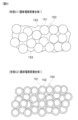
- the forms C1 and C2 shown in FIG. 9 differ in the configuration of the first phase 151 and the second phase 152 of the solid electrolyte composite 150.
- the solid electrolyte composite 150 of form C1 has a random structure in which the first phase 151 and the second phase 152 are randomly mixed.
- the first phase 151 of form C1 is particulate, and the first phase 151 is surrounded by the second phase 152.
- the solid electrolyte composite 150 of form C2 has a core-shell structure with a particulate first phase 151 as a core phase and a second phase 152 as a shell phase.
- the particulate first phase 151 is individually coated with the second phase 152.
- the second phase 152 of form C2 is not integrated, and the second phase 152 is separated for each first phase 151.
- the first phase 151 of the solid electrolyte composite 150 can be made of a material similar to that of the core phase 121 of the negative electrode composite particle 120.
- the second phase 152 of the solid electrolyte composite 150 can be made of a material similar to that of the shell phase 122 of the negative electrode composite particle 120.
- the first phase 151 is an oxide-based ion conductor and an oxide -based solid electrolyte.
- a pyrochlore oxide such as Li1.25La0.58Nb2O6F (LLNOF) or Li1.25La0.58Ta2O6 (LLTOF ) can be used as the first phase 151 .
- the constituent material of the second phase 152 contains at least Li and F in its composition, and examples of the material include LiF and LiNb 6 O 15 F. In this embodiment, LiF is used as the second phase 152.
- the constituent material of the second phase 152 is a material with a lower melting point than the constituent material of the first phase 151. Therefore, when the solid electrolyte composite 150 is manufactured, by heating at a temperature equal to or higher than the melting point of the constituent material of the second phase 152 and lower than the melting point of the constituent material of the first phase 151, the second phase 152 melts, and the contact area between the first phase 151 and the second phase 152 can be increased, thereby reducing the interface resistance.
- the material constituting the second phase 152 has a lower Young's modulus than the material constituting the first phase 151.
- Young's modulus By using a material with a lower Young's modulus for the second phase 152, the contact area between the solid electrolyte layer 15 and the adjacent electrode layer can be increased, and the interface resistance can be reduced.
- the constituent material of the second phase 152 is an amorphous-containing ion conductor that contains at least a portion of an amorphous phase.
- the constituent material of the second phase 152 may be entirely amorphous, or may contain a mixture of amorphous and crystalline phases.
- the constituent material of the second phase 152 contains an amorphous and crystalline phase, it is desirable that the volume ratio of the amorphous phase is equal to or greater than the volume ratio of the crystalline phase.
- Amorphous phase LiF has a lower Young's modulus than crystalline phase LiF. Therefore, by increasing the volume ratio of the amorphous phase in the second phase 152, the contact area between the solid electrolyte layer 15 and the adjacent electrode layer can be increased, and the interface resistance can be reduced.
- the amorphous phase has an irregular particle shape rather than a specific shape. This also increases the contact area between the solid electrolyte layer 15 and the adjacent electrode layer, reducing the interface resistance.
- the pyrochlore oxide of this embodiment has a pyrochlore structure represented by the composition formula "Aa 2- ⁇ Ab (1+ ⁇ )/3 B 2 O 7- ⁇ X ⁇ " .
- O is an oxygen atom
- Aa, Ab, B, and X represent any element or group.
- Aa, Ab, and B are different types of cations
- O and X are different types of anions.
- Aa is an alkali metal cation.
- the pyrochlore oxide contains multiple cations in its composition, including the alkali metal cation Aa and multiple cations Ab and B other than the alkali metal cation Aa. In other words, the pyrochlore oxide contains multiple cations in its composition, including the alkali metal cation Aa.
- pyrochlore oxides have a crystal structure in which a three-dimensional network of octahedra made of BO6 is formed.
- BO6 is arranged with cation B at the center, O at the vertices, and shares the vertices with adjacent BO6 .
- a hexagonal tunnel structure in which cation A and anion X are arranged is formed.
- the cation Aa is an alkali metal cation.
- the alkali metal represented by Aa can be any of Li, Na, K, Rb, and Cs.
- the cation Aa can also be Mg or H, which is not an alkali metal.
- the cation Aa contains at least one selected from Li, Na, K, Rb, Cs, Mg, and H.
- Li is used as Aa.
- the composition ratio (2- ⁇ ) of Aa is within the range of 0 ⁇ (2- ⁇ ) ⁇ 1.4.
- the cation Ab contains at least a lanthanoid. At least one of La, Ce, Nd, and Sm can be used as the lanthanoid represented by Ab. In this embodiment, La is used as Ab.
- the composition ratio of Ab (1+ ⁇ )/3 is within the range of 0.53 ⁇ (1+ ⁇ )/3 ⁇ 1.
- the basic structure of the cation Ab is lanthanoid, and some of the lanthanoids constituting Ab may be replaced with alkaline earth metals (Ca, Mg, Sr, etc.).
- alkaline earth metals Ca, Mg, Sr, etc.
- the pyrochlore oxide of this embodiment the pyrochlore structure in the above composition formula, where 0.6 ⁇ 2.0 and 0 ⁇ 1, contains lanthanoids, which is thought to cause defects in the crystal structure and improve ionic conductivity.
- La is used as Ab.
- the cation A in the general pyrochlore structure formula "A2B2O7" is a composite cation made of lithium metal and lanthanoid. This is thought to contribute to the improvement of the ionic conductivity of the pyrochlore oxide.
- Cation B is a metal cation different from Aa and Ab, and is a transition metal or a metal selected from Groups 13 to 15 elements. B forms an octahedron surrounded by six O atoms in the crystal.
- the transition metal represented by B Group 4 transition metals or Group 5 transition metals can be used, and more specifically, at least one of Nb, Ta, Ti, Zr, Hf, and V can be used.
- the Group 13 element represented by B Al, Ga, and In can be used, as the Group 14 element, Ge and Sn can be used, and as the Group 15 element, Sb and Bi can be used.
- Nb or Ta is used as B.
- the anion X is an anion that can be substituted for the O atoms that constitute the pyrochlore structure.
- X has a different electronegativity and polarizability from the O atoms.
- At least one of O, F, Cl, Br, I, S, OH, and P can be used as the anion represented by X.
- the composition ratio ⁇ of X is within the range of 0 ⁇ 1, and at least a part of the O atoms that constitute the pyrochlore structure is substituted with X.
- F is used as X.
- the pyrochlore oxide of this embodiment has a defect structure in which the crystal contains lattice defects due to some of the O atoms that make up the pyrochlore structure being replaced with anions that have different electronegativity and polarizability from the O atoms. It is believed that the pyrochlore oxide of this embodiment has improved ionic conductivity due to the presence of a defect structure in the pyrochlore structure.
- the composition formula of a general pyrochlore structure is "A 2 B 2 O 7 ", and the composition ratio of the cation A is 2.
- the composition ratios of Aa and Ab are "2- ⁇ " and "(1+ ⁇ )/3", respectively, and 0.6 ⁇ 2.0, so that the sum of the composition ratios of Aa and Ab is less than 2.
- at least one part of Aa and Ab is missing.
- the composition ratio corresponding to the missing parts of Aa and Ab is (2 ⁇ -1)/3.
- a defect structure can also be formed by making the sum of the valences of the cations Aa, Ab, and B and the anions O and X in the above composition formula negative.
- the pyrochlore oxide of this embodiment is a composite anion compound in which the pyrochlore structure contains multiple anions such as O and X, and since the BO 6- coordinated octahedral structure contains an anion represented by X, the alkali metal Aa can be positioned in the center of the space with the BO 6- coordinated octahedron without approaching it. For this reason, it is believed that the pyrochlore oxide of this embodiment has high ionic conductivity when used with an electric field applied, such as in a battery.
- ⁇ , ⁇ , and ⁇ in the above composition formula affect lattice defects and ionic conductivity, it is desirable to use them within appropriate ranges.
- Large values of ⁇ , ⁇ , and ⁇ increase the defect concentration in the crystal lattice, but if they exceed a certain amount, the concentration of the alkali metal represented by Aa decreases, and ionic conductivity decreases. For this reason, it is desirable to control ⁇ within the range of 0.6 ⁇ 2.0, ⁇ within the range of 0 ⁇ 1, and ⁇ within the range of 0 ⁇ 1.
- the pyrochlore type oxide of this embodiment has an ionic conductivity of 1 ⁇ 10 ⁇ 3 S/cm or more, which is significantly higher than other oxide-type solid electrolytes such as garnet-type oxides.
- amorphous LiF is simultaneously formed when producing the pyrochlore oxide.
- LiF which is a raw material for producing the pyrochlore oxide
- amorphous LiF can be formed on the surface of the pyrochlore oxide.
- FIG. 11 shows the method for producing pyrochlore oxide in this embodiment.
- a first mixing step S10, a first firing step S11, a second mixing step S12, a molding step S13, and a second firing step S14 are carried out in this order.
- a lanthanum source, a lithium source, and either a niobium source or a tantalum source are prepared as raw materials for the pyrochlore oxide, and a first mixing step S10 is performed in which these are mixed.
- Metal oxides and metal carbonates can be used as the lanthanum source, the lithium source, the niobium source, and the tantalum source.
- La 2 O 3 is used as the lanthanum source, Li 2 CO 3 as the lithium source, Nb 2 O 5 as the niobium source, and Ta 2 O 5 as the tantalum source.
- La 2 O 3 , Li 2 CO 3 , and either Nb 2 O 5 or Ta 2 O 5 are mixed in a predetermined ratio.
- the first firing step S11 is performed to fire the mixture prepared in the first mixing step.
- the first firing step S11 two-stage firing is performed.
- the mixture is pre-fired in air at 500°C for 6 hours. Pre-fire removes moisture and other substances from the mixture, and can increase reactivity.
- the mixture is pre-fired in air at 1200 ° C for 4 hours. This produces Li0.5La0.5Nb2O6 or Li0.5La0.5Ta2O6 , which is a precursor of the target product.
- a second mixing step S12 is performed in which a fluorine source is prepared as a raw material and mixed with the precursor.
- a metal fluoride can be used as the fluorine source.
- LiF and LaF3 are used as the fluorine source.
- LiF is a fluorine source and a lithium source
- LaF3 is a fluorine source and a lanthanum source.
- LiF and LaF3 are mixed with the precursor in a predetermined ratio. In this embodiment, LiF is added in excess of the amount required to produce a pyrochlore type oxide.
- the mixed powder of the precursor, LiF, and LaF3 is processed into a pellet shape, and a molding step S13 is performed in which the mixed powder is pressed at 100 MPa. As a result, the mixture of the precursor, LiF, and LaF3 is molded into a pellet shape.
- a second firing step S14 is performed in which the mixture of the precursor, LiF, and LaF3 is fired.
- the mixture of the precursor, LiF, and LaF3 is heated and fired at 1000° C. for 6 hours in a nitrogen atmosphere.
- firing may be performed in a sealed state or in a state covered with a mother powder in order to suppress composition deviation due to volatilization of Li element and F element.
- the product of the second firing step is cooled to obtain a pyrochlore oxide represented by the composition formula " Li1.25La0.58Nb2O6F " or " Li1.25La0.58Ta2O6F ".
- the pyrochlore oxide thus produced is in the form of particles.
- the outer surface of the pyrochlore oxide is covered with LiF, and particles with a core-shell structure having a core phase of pyrochlore oxide and a shell phase of LiF can be obtained.
- the amorphization of LiF can be promoted. Specifically, by increasing the cooling rate of the product, the amorphization of LiF can be promoted, and the volume ratio of amorphous material can be increased.
- FIG. 12 is an SEM image of LLNOF, a pyrochlore oxide, and amorphous-containing LiF, which contains amorphous material.
- the upper part of FIG. 12 shows a core-shell structure in which LLNOF is covered with amorphous-containing LiF, and the lower part shows a random structure in which LLNOF and amorphous-containing LiF are randomly mixed.
- the manufacturing method of this embodiment provides a composite of LLNOF and amorphous-containing LiF, as shown in FIG. 12.
- FIG. 13 is an SEM image of a positive electrode composite particle 140.
- NMC is used as the positive electrode active material 141
- the coating layer 142 has a random structure in which LLNOF and amorphous-containing LiF are randomly mixed.
- a method for manufacturing the anode layer 12 using a 3D printer will be described.
- a photolithography method or an extrusion method can be used as a method for manufacturing the anode layer 12 using a 3D printer.
- a solid electrolyte layer 15 is used as a substrate, and the anode layer 12 is formed on the solid electrolyte layer 15.
- LLNOF is used as the oxide-based ion conductor
- amorphous-containing LiF is used as the amorphous-containing ion conductor.
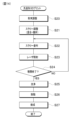
- a powder preparation step S20 is performed to prepare the negative electrode composite particles 120, which are the raw material powder of the negative electrode layer 12.
- particles with a core-shell structure made of LLNOF and amorphous-containing LiF were used as the negative electrode composite particles 120.
- the average particle size of the negative electrode composite particles 120 was set to 2 ⁇ m.
- the ratios of LLNOF and amorphous-containing LiF in the negative electrode composite particles 120 were set to 90 vol% and 10 vol%.
- the slurry preparation step S21 is performed.
- the negative electrode composite particles 120 and the acrylic photocurable resin are mixed and stirred to prepare a slurry.
- the slurry is a suspension in which solid particles are dispersed in a solvent, and is a highly viscous fluid.
- the ratio of the negative electrode composite particles 120 and the acrylic photocurable resin in the slurry was 52 vol% and 48 vol%.
- a slurry application step S22 is performed.
- the slurry is applied in layers using a 3D printer.
- the thickness of the slurry is set to 10 ⁇ m.
- the slurry is applied onto the solid electrolyte layer 15.
- the slurry can be applied in a pattern according to the shape of the negative electrode layer 12 to be formed.
- the pores in the negative electrode layer 12 may be formed by the pattern of the structure, or may be formed using a pore-forming agent. When a pore-forming agent is used, the pore-forming agent may be mixed into the slurry.
- the laser irradiation process S23 is performed.
- the applied slurry is irradiated with ultraviolet light to harden the photocurable resin.
- the laser diameter of the laser irradiation is 10 ⁇ m. As a result, a layered structure is formed.
- judgment process S24 it is determined whether or not a predetermined number of layers have been stacked.
- the number of layers is four.
- the slurry application process S22 and the laser irradiation process S23 are repeated until the predetermined number of layers have been stacked. This results in a laminated structure in which layered structures are stacked.
- S22 to S24 are the structure molding process in which the laminated structure is molded.
- a cleaning step S25 is performed to remove the portions of the laminated structure that have not been hardened by laser irradiation.
- the cleaning step S25 ultrasonic cleaning in various solvents, immersion cleaning, cleaning using suction filtration, etc. can be used.
- the solvent used in the cleaning step can be a photocurable resin similar to the photocurable resin used in the slurry, ethanol, etc.
- a degreasing step S26 is performed to remove the photocurable resin that has been cured by laser irradiation from the laminated structure.
- the degreasing step S26 can be performed by baking the laminated structure at a temperature of, for example, about 600°C.
- the firing step S27 is performed.
- the firing step S27 can be performed by heating the laminated structure at a temperature of, for example, about 1000°C. This allows the negative electrode layer 12 to be produced.
- the amorphous-containing LiF contained in the negative electrode composite particles 120 can promote interparticle bonding during sintering, and can densify the negative electrode layer 12 after sintering to form a dense structure.
- firing can be performed in a sealed state or in a state covered with a mother powder in order to suppress composition deviation due to volatilization of the Li element and the F element.
- the negative electrode layer 12 can be manufactured using a stereolithography 3D printer.
- the negative electrode layer 12 is formed on the solid electrolyte layer 15.
- the negative electrode composite particles 120, the dispersant, and the binder are mixed and stirred to prepare the slurry.
- a tube extrusion process S28 is performed.
- the slurry is applied in layers using a 3D printer.
- the slurry is applied onto the solid electrolyte layer 15.
- the slurry is applied in a pattern that corresponds to the shape of the negative electrode layer 12 to be formed.
- a drying step S29 is performed.
- the applied slurry is dried. This forms a layered structure.
- the applied slurry may be heated.
- S28, S29, and S24 are the structure molding process in which the laminated structure is molded.
- a firing process S27 is performed. This allows the negative electrode layer 12 to be manufactured using an extrusion-type 3D printer.
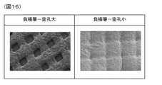
- FIG. 16 is an SEM image of the manufactured negative electrode layer 12.
- the negative electrode layer 12 shown in FIG. 16 is formed in a lattice shape.
- the two negative electrode layers 12 shown in FIG. 16 have different pore sizes.
- the negative electrode layer 12 shown on the left side has larger pores than the negative electrode layer 12 shown on the right side.
- Examples A1 to A4 and comparative examples A1 to A3 differ in the material of the core phase 121, the amorphous volume ratio of the shell phase 122, the presence or absence of the shell phase 122, and the presence or absence of an organic coating.
- the Li residual ratio is the ratio of the amount of lithium contained in the raw powder after it has been slurried to the amount of lithium contained in the raw powder before it has been slurried. If the amount of lithium contained in the raw powder does not change before and after it has been slurried, the Li residual ratio will be 100%.
- Examples A1 to A4 raw material powder was used in which the core phase 121 of an oxide-based ion conductor was coated with the shell phase 122 of an amorphous-containing ion conductor.
- Comparative Example A1 raw material powder was used in which the core phase 121 of an oxide-based ion conductor was coated with the shell phase 122 of an ion conductor that was 100% crystalline.
- Comparative Example A2 raw material powder consisting of only an oxide-based ion conductor was used.
- Comparative Example A3 raw material powder in which an oxide-based ion conductor was subjected to an organic coating was used.
- Example A1 LLNOF was used as the core phase 121, and 100% amorphous LiF was used as the shell phase 122.
- Example A2 to A4 and Comparative Examples A1 to A3 differences from Example A1 will be explained.
- Example A2 uses 50% crystalline and 50% amorphous LiF as the shell phase 122.
- Example A3 uses LLTOF as the core phase 121.
- Example A4 uses LLZ as the core phase 121.
- Comparative Example A1 uses 100% crystalline LiF as the shell phase 122.
- Comparative Example A2 uses LLZ as the core phase 121, and does not have a shell phase 122.
- Comparative Example A3 uses LLZ as the core phase 121, does not have a shell phase 122, and has an organic coating.
- Example A1 LLNOF was used as the core phase 121.
- the Li residual ratio was 100%, and the density after sintering was 88%.
- Example A2 the Li residual ratio was 99%, and the density after sintering was 85%.
- Comparative Example A1 the Li residual ratio was 95%, and the density after sintering was 82%.
- Example A1 and A2 which used amorphous-containing LiF, the Li residual ratio and density after sintering were improved compared to Comparative Example A1, which used 100% crystalline LiF. Since the amorphous phase has a lower Young's modulus and is amorphous than the crystalline phase, it is believed that in Examples A1 and A2, which used amorphous-containing LiF, the coverage of the core phase 121 by the shell phase 122 was high, and the elution of lithium ions from the core phase 121 was suppressed. Furthermore, since amorphous-containing LiF promotes interparticle bonding during sintering, it is believed that the density after sintering was improved in Examples A1 and A2. Example A1, which has a higher volume ratio of the amorphous phase than Example A2, has a higher Li residual ratio and density after sintering than Example A2.
- Example A3 the Li residual ratio was 100%, and the density after sintering was 87%. Even in Example A3, which used LLTOF as the core phase 121, high values were obtained for the Li residual ratio and density after sintering by using 100% amorphous LiF as the shell phase 122.
- Example A4 the residual Li ratio was 92%, and the density after sintering was 80%.
- Comparative Example A2 the residual Li ratio was 60%.
- coating was not possible, and a sintered body could not be obtained.
- Comparative Example A3 the residual Li ratio was 100%, and the density after sintering was 72%.
- Comparative Example A2 which uses only LLZ, the Li residual ratio is significantly reduced, and furthermore, coating using a 3D printer was not possible.
- Comparative Example A3 in which an organic coating is applied to LLZ, the Li residual ratio is high, but the density after sintering is low due to the effect of the specific surface area being enlarged by the organic coating.
- Example A4 which has a shell phase 122 of amorphous LiF
- the Li residual ratio is significantly improved compared to Comparative Example A2.
- Example A4 although the Li residual ratio is lower than Comparative Example A3, the density after sintering is improved. This is thought to be because the 100% amorphous LiF used as the shell phase 122 promotes interparticle bonding during sintering, improving the density after sintering.
- Examples A1 and A2 which use pyrochlore-type oxides (LLNOF, LLTOF) as the core phase 121, with Example A4, which uses a garnet-type oxide (LLZ) as the core phase 121, Examples A1 and A2 have a higher Li residual ratio and higher density after sintering than Example A4. This is thought to be because pyrochlore-type oxides have a lower melting point and lower Young's modulus than garnet-type oxides, resulting in a higher Li residual ratio and higher density after sintering.
- Examples B1 to B8 and comparative examples B1 to B7 differ in the positive electrode active material 141 or the coating layer 142.
- the coverage in Figure 18 is the coverage of the positive electrode active material 141 by the coating layer 142.
- the discharge characteristics in Figure 18 are the dischargeable time until the secondary battery 10 reaches the lower limit voltage when discharged at 5C.
- the coverage and discharge characteristics are shown as relative values when the value of comparative example B1 is set to 100%.
- Example B1 NMC is used as the positive electrode active material 141, LLNOF is used as the first phase 142a of the coating layer 142, and 100% amorphous LiF is used as the second phase 142b, with the volume ratios of the first phase 142a and the second phase 142b being 90 vol% and 10 vol%.
- Examples B2 to B8 and Comparative Examples B1 to B7 explain the differences from Example B1.
- Example B2 50% crystalline and 50% amorphous LiF is used as the second phase 142b.
- Example B3 the volume ratio of the first phase 142a to the second phase 142b is 70 vol% and 30 vol%.
- Example B4 LLTOF is used as the first phase 142a.
- Example B5 LMFP is used as the positive electrode active material 141.
- the coating layer 142 is provided with a third phase 142c made of carbon, and the volume ratios of the first phase 142a, the second phase 142b, and the third phase 142c are 89 vol%, 8 vol%, and 3 vol%.
- Example B7 LLZ is used as the first phase 142a.
- Example B8 the volume ratios of the first phase 142a and the second phase 142b are both 50 vol%.
- Comparative Example B1 uses 100% crystalline LiF as the second phase 142b.
- Comparative Example B2 uses 100% crystalline LiF as the second phase 142b, and the volume ratios of the first phase 142a and the second phase 142b are both 50 vol%.
- Comparative Example B3 does not have a second phase 142b.
- Comparative Example B4 uses LLTOF as the first phase 142a, and does not have a second phase 142b.
- Comparative Example B5 does not have a first phase 142a, and uses 100% crystalline LiF as the second phase 142b.
- Comparative Example B6 uses LLZ as the first phase 142a, and uses 100% crystalline LiF as the second phase 142b.
- Comparative Example B7 uses LiNbO3 as the first phase 142a, and does not have a second phase 142b.
- NMC is used for the positive electrode active material 141
- LLNOF is used for the first phase 142a of the coating layer 142.
- Example B4 LLTOF is used as the first phase 142a, but amorphous LiF is used as the second phase 142b, resulting in a higher coverage rate and better discharge characteristics than Comparative Example B1.
- Example B5 LMFP is used as the positive electrode active material 141, but by providing a coating layer 142 made of LLNOF and 100% amorphous LiF, a higher coverage rate and higher discharge characteristics are obtained than in Comparative Example B1.
- Example B6 the discharge characteristics are improved compared to Example B1.
- a third phase 142c having electronic conductivity is provided in the coating layer 142, and it is believed that the presence of the third phase 142c improves the discharge characteristics.
- Example B7 NMC is used for the positive electrode active material 141, and LLZ is used for the first phase 142a of the coating layer 142.
- Example B7 which uses 100% amorphous LiF as the second phase 142b, has improved coverage and discharge characteristics compared to Comparative Example B6, which uses 100% crystalline LiF.
- Example B8 and Comparative Example B2 NMC is used for the positive electrode active material 141, LLNOF is used for the first phase 142a of the coating layer 142, and the volume ratios of the first phase 142a and the second phase 142b are both 50 vol%.
- Example B8 which uses 100% amorphous LiF as the second phase 142b, has improved coverage and discharge characteristics compared to Comparative Example B2, which uses 100% crystalline LiF.
- Comparative examples B3 and B4 which do not have the second phase 142b, have significantly lower coverage and discharge characteristics than comparative example B1. It is believed that in comparative examples B3 and B4, the low coverage causes the positive electrode active material 141 to react with other materials, such as the solid electrolyte, resulting in increased resistance and reduced discharge characteristics.
- Comparative example B5 in which the coating layer 142 is made only of 100% crystalline LiF, has a higher coverage rate than comparative example B1, but the discharge characteristics are significantly reduced. It is believed that because LiF has low ionic conductivity, the resistance of the coating layer 142 increases, causing the discharge characteristics to decrease.
- Comparative example B7 which uses LiNbO3 as the coating layer 142, has a higher coverage rate than comparative example B1, but the discharge characteristics are significantly worse. It is believed that because LiNbO3 has low ionic conductivity, the resistance of the coating layer 142 increases, causing the discharge characteristics to deteriorate.
- the coating layer 142 contains a first phase 142a having high ionic conductivity and a second phase 142b containing an amorphous phase.
- the second phase 142b containing an amorphous phase has a low Young's modulus and is amorphous, so that it is possible to improve the contact between the positive electrode active material 141 and the coating layer 142, and it is possible to improve the coverage of the positive electrode active material 141 by the coating layer 142.
- This makes it possible to improve the ionic conductivity of the coating layer 142 by the first phase 142a having high ionic conductivity, while suppressing the reaction of the positive electrode active material 141 with other materials.
- the amorphous-containing ionic conductor of the second phase 142b contained in the coating layer 142 is a material with a lower melting point than the first phase 142a. This also improves the contact between the positive electrode active material 141 and the first phase 142a. This improves the coverage of the positive electrode active material 141 by the coating layer 142, and improves the ionic conductivity of the positive electrode layer 14 while suppressing reactions with other materials.
- a pyrochlore-type oxide is used as the first phase 142a of the coating layer 142. Since pyrochlore-type oxide has a higher ionic conductivity than other oxide-type solid electrolytes, the ionic conductivity of the coating layer 142 can be improved.
- pyrochlore oxides have high oxidation resistance. Therefore, by using pyrochlore oxides for the coating layer 142, it is possible to achieve both low resistance and high charge/discharge stability.
- the volume ratio of the first phase 142a in the coating layer 142 of the positive electrode composite particle 140 is set to be equal to or greater than the volume ratio of the second phase 142b. In this way, by increasing the volume ratio of the first phase 142a, which has high ionic conductivity, the ionic conductivity of the coating layer 142 can be improved.
- a material containing at least Li and F in its composition is used as the second phase 142b of the coating layer 142. This makes it possible to lower the Young's modulus of the second phase 142b and improve the contact between the positive electrode active material 141 and the first phase 142a.
- an ion conductor containing at least a portion of an amorphous phase is used as the second phase 142b of the coating layer 142, and the volume ratio of the amorphous phase in the second phase 142b is equal to or greater than the volume ratio of the crystalline phase.
- a third phase 142c having electronic conductivity can be provided in the coating layer 142. This can improve the electronic conductivity of the positive electrode layer 14 and reduce the amount of conductive additive in the positive electrode layer 14.
- a solid electrolyte composite 150 including a first phase 151 made of an oxide-based ion conductor and a second phase 152 made of an amorphous ion conductor is used as the solid electrolyte layer 15.
- the amorphous ion conductor of the second phase 152 has a lower Young's modulus than the first phase 151 and is an amorphous material, which can increase the contact area between the solid electrolyte layer 15 and the electrode layers adjacent to the solid electrolyte layer 15, such as the negative electrode layer 12 and the positive electrode layer 14. This can reduce the interface resistance between the solid electrolyte layer 15 and the adjacent electrode layers, and can improve ion conductivity.
- a pyrochlore oxide is used as the first phase 151 of the solid electrolyte composite 150.
- Pyrochlore oxides have higher ionic conductivity than other oxide-type solid electrolytes, and the solid electrolyte composite 150 contains a pyrochlore oxide, which can improve the ionic conductivity of the solid electrolyte layer 15.
- a material containing at least Li and F in its composition is used as the second phase 152 of the solid electrolyte composite 150. This makes it possible to lower the Young's modulus of the second phase 152 and increase the contact area between the solid electrolyte layer 15 and the adjacent electrode layer. This makes it possible to reduce the interface resistance between the solid electrolyte layer 15 and the adjacent electrode layer and improve ion conductivity.
- the negative electrode layer 12 is manufactured using a slurry containing the negative electrode composite particles 120.
- the negative electrode composite particles 120 contain a core phase 121 made of an oxide-based ion conductor and a shell phase 122 made of an amorphous-containing ion conductor containing at least a portion of an amorphous phase.
- the amorphous-containing ion conductor of the shell phase 122 has a lower Young's modulus than the core phase 121 and is an amorphous material, which can improve the coverage of the core phase 121 by the shell phase 122. This can prevent the oxide-based ion conductor of the negative electrode composite particles 120 from reacting with the solvent in the slurry, and can prevent lithium ions, which are conductive ions, from eluting from the oxide-based ion conductor.
- the amorphous-containing LiF contained in the shell phase 122 can promote interparticle bonding during sintering, increasing the density of the negative electrode layer 12 after sintering and forming a dense structure. This makes it possible to suppress short circuits caused by lithium metal precipitation inside the structure when lithium metal precipitates in the negative electrode layer 12.
- a pyrochlore oxide is used as the core phase 121 of the negative electrode composite particle 120.
- Pyrochlore oxides have higher ionic conductivity than other oxide-type solid electrolytes, and the negative electrode composite particle 120 contains a pyrochlore oxide, which can improve the ionic conductivity of the negative electrode layer 12.
- lithium ions are less likely to dissolve from pyrochlore oxides than from other oxides such as garnet-type oxides. Therefore, by using a pyrochlore oxide as the oxide-based ion conductor of the core phase 121, the dissolution of lithium ions can be effectively suppressed.
- a material containing at least Li and F in its composition is used as the shell phase 122 of the negative electrode composite particle 120. This makes it possible to lower the Young's modulus of the shell phase 122 and improve the coverage of the core phase 121 by the shell phase 122. This makes it possible to suppress the elution of lithium ions, which are conductive ions, from the oxide-based ion conductor of the negative electrode composite particle 120.
- an ion conductor containing at least a portion of an amorphous phase is used as the shell phase 122 of the negative electrode composite particle 120, and the volume ratio of the amorphous phase in the shell phase 122 is equal to or greater than the volume ratio of the crystalline phase. This makes it possible to lower the Young's modulus of the shell phase 122 and improve the coverage of the core phase 121 by the shell phase 122.
- the volume ratio of the core phase 121 in the negative electrode composite particle 120 is set to be equal to or greater than the volume ratio of the shell phase 122. Since the constituent material of the shell phase 122 has a higher ionic conductivity than the constituent material of the core phase 121, the ionic conductivity of the negative electrode composite particle 120 can be increased by increasing the volume ratio of the core phase 121 in the negative electrode composite particle 120.
- the negative electrode layer 12 is manufactured from the slurry using a 3D printer. This makes it easy to manufacture the negative electrode layer 12 with a regular porous structure in which pores are regularly formed.
- the negative electrode layer 12 is manufactured using a 3D printer that uses a photo-lithography method in which a photo-curable resin is cured by laser irradiation.
- the photo-curable resin easily reacts with an oxide-based ion conductor in the slurry.
- a negative electrode composite particle 120 in which a core phase 121 made of an oxide-based ion conductor is coated with a shell phase 122 made of an amorphous-containing ion conductor, it is possible to suppress the reaction between the oxide-based ion conductor of the core phase 121 and the photo-curable resin and the elution of lithium ions, which are conductive ions, from the oxide-based ion conductor.
- the solid content ratio of the slurry is set to a range of 30 to 60 vol.%. This ensures that the negative electrode composite particles 120 are slurried, and the density of the negative electrode layer 12 after sintering can be increased.
- a light absorbing material can be included in the slurry.
- a light absorbing material can be included in the slurry.
- scattering of the laser light can be suppressed when the slurry is irradiated with a laser by a 3D printer. This allows the stereolithography 3D printer to achieve the desired modeling width and perform modeling with high precision.
- the negative electrode layer 12 of the second embodiment has a pore distribution in which the porosity changes from the side closer to the solid electrolyte layer 15 to the side farther from the solid electrolyte layer 15, with the porosity increasing closer to the solid electrolyte layer 15.
- the porosity is low on the side farther from the solid electrolyte layer 15 (i.e., the side closer to the negative electrode current collector 11), and the porosity is high on the side closer to the solid electrolyte layer 15.
- the pore diameter of the anode layer 12 is smaller on the side farther from the solid electrolyte layer 15, and larger on the side closer to the solid electrolyte layer 15. If the pore diameter of the anode layer 12 is uniform, the porosity on the side closer to the solid electrolyte layer 15 can be increased by making the number of pores on the side closer to the solid electrolyte layer 15 greater than the number of pores on the side farther from the solid electrolyte layer 15.
- FIG. 19 shows an example in which pores in the anode layer 12 are irregularly formed using a pore-forming agent.
- the conduction rate of electrons is faster than the conduction rate of lithium ions.
- lithium metal is preferentially precipitated from pores closer to the solid electrolyte layer 15.
- the pores closer to the solid electrolyte layer 15 of the negative electrode layer 12 are filled with lithium metal, lithium metal precipitation occurs competitively in the pores farther from the solid electrolyte layer 15 of the negative electrode layer 12 and in the solid electrolyte layer 15. If lithium metal precipitation occurs in the solid electrolyte layer 15, it may lead to a short circuit.
- the solid electrolyte layer 15 of the second embodiment uses a solid electrolyte composite 150 containing a second phase 152 of amorphous-containing LiF, which can improve the contact between the negative electrode layer 12 and the solid electrolyte layer 15. This makes it possible to suppress a decrease in the contact between the negative electrode layer 12 and the solid electrolyte layer 15, even if the porosity of the negative electrode layer 12 on the side closer to the solid electrolyte layer 15 is increased.
- the pore distribution of the anode layer 12 may be such that the porosity increases from the side farther from the solid electrolyte layer 15 toward the side closer to the solid electrolyte layer 15, and the porosity may change continuously or in stages. In order to deposit lithium metal as uniformly as possible in the pores throughout the anode layer 12, it is desirable for the porosity to change continuously.
- the anode layer 12 is manufactured using a 3D printer, for example, the material is stacked in multiple layers, and the porosity is fixed for each layer. For this reason, a configuration in which the porosity of the anode layer 12 changes in stages has the advantage of being easier to manufacture.
- FIG. 20 shows a partially enlarged cross section of the negative electrode layer 12 of the third embodiment.
- an electron conductive layer 123 having electron conductivity is formed on the surface of the negative electrode layer 12.
- the electron conductive layer 123 is provided on the inner surface of the pores of the negative electrode layer 12.
- the electron conductive layer 123 can be formed by coating a carbon material such as carbon black.
- the electronic conductivity of the negative electrode layer 12 can be improved, and the deposition of lithium metal in the negative electrode layer 12 can be promoted.
- the conductive additive in the negative electrode layer 12 can be reduced.
- FIG. 21 shows a partially enlarged cross section of the negative electrode layer 12 of the fourth embodiment.
- the negative electrode layer 12 includes an ion-electron conductive phase 124.
- the ion-electron conductive phase 124 is composed of a material having ionic conductivity and electronic conductivity.
- the ion-electron conductive phase 124 can be obtained by imparting electronic conductivity to a pyrochlore oxide used as the core phase 121 of the negative electrode composite particle 120, for example.
- a pyrochlore oxide having ionic conductivity to a reduction treatment
- the pyrochlore oxide can be imparted with electronic conductivity in addition to ionic conductivity.
- Metals that form alloys with Li such as Ag, Au, Sn, and In, can also be used as the ion-electron conductive phase 124.
- the inclusion of the ion-electron conductive phase 124 in the negative electrode layer 12 can improve the ionic conductivity and electronic conductivity of the negative electrode layer 12, and can promote lithium metal deposition in the negative electrode layer 12. In addition, the inclusion of the ion-electron conductive phase 124 in the negative electrode layer 12 can reduce the amount of conductive additive in the negative electrode layer 12.
- the positive electrode layer 14 includes a solid electrolyte composite 143.
- the solid electrolyte composite 143 of the positive electrode layer 14 can have a configuration similar to that of the solid electrolyte composite 150 of the solid electrolyte layer 15.
- the positive electrode layer 14 may include an electrolyte solution and a polymer.
- the solid electrolyte composite 143 provided in the positive electrode layer 14 is a composite having multiple phases including at least a first phase 143a and a second phase 143b, and can also be called a positive electrode composite.
- the first phase 143a is an oxide-based ion conductor
- the second phase 143b is an amorphous-containing ion conductor that includes at least an amorphous phase in a portion thereof.
- the material constituting the second phase 143b has a lower melting point and a lower Young's modulus than the material constituting the first phase 143a.
- the solid electrolyte composite 143 provided in the positive electrode layer 14 may have a random configuration in which the first phase 143a and the second phase 143b are randomly provided, as shown in form D1 of FIG. 23, or may have a core-shell structure in which the first phase 143a is the core phase and the second phase 143b is the shell phase, as shown in form D2 of FIG. 23.
- a pyrochlore-type oxide such as LLNOF or LLTOF
- amorphous-containing ion conductor of the second phase 143b amorphous-containing LiF containing an amorphous phase can be used. It is desirable that the volume ratio of the amorphous phase in the amorphous-containing LiF of the second phase 143b is equal to or greater than the volume ratio of the crystalline phase.
- the positive electrode layer 14 with a solid electrolyte composite including a first phase 143a made of an oxide-based ion conductor and a second phase 143b made of an amorphous-containing ion conductor, the ionic conductivity of the positive electrode layer 14 can be improved.
- the solid electrolyte composite provided in the positive electrode layer 14 contains the second phase 143b made of an amorphous-containing ion conductor, which improves the contact between the positive electrode layer 14 and the solid electrolyte layer 15 and reduces the interface resistance.
- the present disclosure is applied to a lithium ion battery in which the conductive ions are lithium ions, but the present disclosure may also be applied to secondary batteries in which the conductive ions are different. Specifically, the present disclosure may be applied to potassium ion batteries in which potassium ions are conductive, sodium ion batteries in which sodium ions are conductive, and the like.
- the positive electrode composite particles 140 were combined with a solid electrolyte layer 15 made of an oxide-based solid electrolyte (pyrochlore-type oxide, garnet-type oxide), but the positive electrode composite particles 140 may also be combined with a solid electrolyte layer 15 made of a sulfide-based solid electrolyte.
- oxide-based solid electrolyte pyrochlore-type oxide, garnet-type oxide
- the positive electrode composite particles 140 may also be combined with a solid electrolyte layer 15 made of a sulfide-based solid electrolyte.
- the positive electrode active material 141 was used as the ceramic particles that undergo an oxidation-reduction reaction, but materials other than the positive electrode active material 141 may be used as the ceramic particles.
- the negative electrode active material may be used as the ceramic particles, and the ceramic composite particles may be made in which the negative electrode active material is coated with a coating layer.
- SOEC solid oxide electrolysis cell
- the electrode active material may be used as the ceramic particles, and the ceramic composite particles may be made in which the electrode active material is coated with a coating layer.
- the secondary battery 10 is an anode-free battery in which no negative electrode active material is provided in the initial state.
- the negative electrode layer 12 may be configured to have a negative electrode active material provided in the initial state.
- the negative electrode layer 12 does not need to be a porous body.
- an oxide-based negative electrode active material e.g., Li 4 Ti 5 O 12 , TiO 2 (B), TiNb 2 O 7
- Li metal may be vapor-deposited on the surface of the porous body.
- the negative electrode layer 12 was formed using a slurry containing composite particles composed of a core phase and a shell phase, but a slurry containing composite particles may also be used to form an ion-conductive structure other than the negative electrode layer 12.
- the negative electrode layer 12 of the secondary battery 10 was produced by a wet process using a slurry in which particles are dispersed in a solvent, but this is not limiting, and the secondary battery 10 may also be produced by a dry process that does not use a solvent.
- the secondary battery 10 described in each of the above embodiments may also be configured as a bipolar battery.
- a bipolar battery has a structure in which multiple battery cells are stacked and connected in series, and adjacent battery cells share a current collector. In other words, the current collector that contacts the positive electrode of one adjacent battery cell contacts the negative electrode of the other adjacent battery cell.
- the electrode structure and secondary battery disclosed in this specification have the following features.
- a solid electrolyte layer (15) composed of a composite (150) of a first phase (151) made of an oxide-based ion conductor and a second phase (152) made of an amorphous-containing ion conductor at least partially containing an amorphous phase;
- the electrode structure has a Young's modulus smaller than that of the oxide-based ion conductor.
- IItem 2 2.
- the composition formula of the pyrochlore oxide is Aa 2- ⁇ Ab (1+ ⁇ )/3 B 2 O 7- ⁇ X ⁇ , 3.
- An electrode structure according to item 2 wherein Aa is an alkali metal, Ab contains at least a lanthanoid, B is a cationic metal different from Aa and Ab, X is an anion that can be substituted for an O atom constituting the pyrochlore type oxide, and in the composition formula, ⁇ is within the range of 0.6 ⁇ 2.0, ⁇ is within the range of 0 ⁇ 1, and ⁇ is within the range of 0 ⁇ 1, and the electrode structure includes a defect structure.
- the pair of electrode layers includes a positive electrode layer (14) having a positive electrode active material (141), 6.
- the negative electrode layer does not initially contain a negative electrode active material, 8.
- (Item 9) 9.
- the ion-electron conductive phase is a pyrochlore type oxide.
- the negative electrode layer has a porosity distribution in which the porosity changes from a side closer to the solid electrolyte layer to a side farther from the solid electrolyte layer, and the porosity becomes higher toward the solid electrolyte layer.
- Item 13 Item 13. The electrode structure according to item 12, wherein the negative electrode layer has a porosity that changes continuously.
- the electrode structure according to item 12 wherein the negative electrode layer has a porosity that changes stepwise.
- the oxide-based ion conductor contains at least one of a pyrochlore-type oxide and a garnet-type oxide, 2.
- a secondary battery comprising the electrode structure according to any one of items 1 to 15.
Landscapes
- Chemical & Material Sciences (AREA)
- Chemical Kinetics & Catalysis (AREA)
- Electrochemistry (AREA)
- General Chemical & Material Sciences (AREA)
- Engineering & Computer Science (AREA)
- Manufacturing & Machinery (AREA)
- Physics & Mathematics (AREA)
- Condensed Matter Physics & Semiconductors (AREA)
- General Physics & Mathematics (AREA)
- Inorganic Chemistry (AREA)
- Materials Engineering (AREA)
- Secondary Cells (AREA)
Priority Applications (1)
| Application Number | Priority Date | Filing Date | Title |
|---|---|---|---|
| JP2025554618A JPWO2025094636A1 (https=) | 2023-10-31 | 2024-10-11 |
Applications Claiming Priority (2)
| Application Number | Priority Date | Filing Date | Title |
|---|---|---|---|
| JP2023186671 | 2023-10-31 | ||
| JP2023-186671 | 2023-10-31 |
Publications (1)
| Publication Number | Publication Date |
|---|---|
| WO2025094636A1 true WO2025094636A1 (ja) | 2025-05-08 |
Family
ID=95582851
Family Applications (1)
| Application Number | Title | Priority Date | Filing Date |
|---|---|---|---|
| PCT/JP2024/036394 Pending WO2025094636A1 (ja) | 2023-10-31 | 2024-10-11 | 電極構造体および二次電池 |
Country Status (2)
| Country | Link |
|---|---|
| JP (1) | JPWO2025094636A1 (https=) |
| WO (1) | WO2025094636A1 (https=) |
Citations (6)
| Publication number | Priority date | Publication date | Assignee | Title |
|---|---|---|---|---|
| JP2014229579A (ja) * | 2013-05-27 | 2014-12-08 | 株式会社オハラ | リチウムイオン伝導性無機固体複合体 |
| JP2021136215A (ja) * | 2020-02-28 | 2021-09-13 | 日産自動車株式会社 | リチウムイオン二次電池 |
| JP2022151220A (ja) * | 2021-03-26 | 2022-10-07 | 太陽誘電株式会社 | 固体電解質、全固体電池、固体電解質の製造方法、および全固体電池の製造方法 |
| JP2023044064A (ja) * | 2021-09-17 | 2023-03-30 | 株式会社デンソー | 全固体電池 |
| JP7338805B1 (ja) * | 2023-01-19 | 2023-09-05 | 株式会社デンソー | 二次電池用固体電解質およびそれを用いた二次電池 |
| JP2023132180A (ja) * | 2022-03-10 | 2023-09-22 | 株式会社デンソー | 二次電池用固体電解質および二次電池 |
-
2024
- 2024-10-11 WO PCT/JP2024/036394 patent/WO2025094636A1/ja active Pending
- 2024-10-11 JP JP2025554618A patent/JPWO2025094636A1/ja active Pending
Patent Citations (6)
| Publication number | Priority date | Publication date | Assignee | Title |
|---|---|---|---|---|
| JP2014229579A (ja) * | 2013-05-27 | 2014-12-08 | 株式会社オハラ | リチウムイオン伝導性無機固体複合体 |
| JP2021136215A (ja) * | 2020-02-28 | 2021-09-13 | 日産自動車株式会社 | リチウムイオン二次電池 |
| JP2022151220A (ja) * | 2021-03-26 | 2022-10-07 | 太陽誘電株式会社 | 固体電解質、全固体電池、固体電解質の製造方法、および全固体電池の製造方法 |
| JP2023044064A (ja) * | 2021-09-17 | 2023-03-30 | 株式会社デンソー | 全固体電池 |
| JP2023132180A (ja) * | 2022-03-10 | 2023-09-22 | 株式会社デンソー | 二次電池用固体電解質および二次電池 |
| JP7338805B1 (ja) * | 2023-01-19 | 2023-09-05 | 株式会社デンソー | 二次電池用固体電解質およびそれを用いた二次電池 |
Also Published As
| Publication number | Publication date |
|---|---|
| JPWO2025094636A1 (https=) | 2025-05-08 |
Similar Documents
| Publication | Publication Date | Title |
|---|---|---|
| JP6904423B2 (ja) | 共焼成型全固体電池 | |
| CN106159312B (zh) | 固体电解质电池及其制造方法、电极复合体、复合固体电解质 | |
| JP7338805B1 (ja) | 二次電池用固体電解質およびそれを用いた二次電池 | |
| JP5527414B2 (ja) | セラミックス積層体の製造方法 | |
| JP5987103B2 (ja) | 全固体イオン二次電池 | |
| CA3043171A1 (en) | All-solid-state li ion batteries comprising mechanically flexible ceramic electrolytes and manufacturing methods for the same | |
| KR20200057047A (ko) | 2차 전지 | |
| KR20100032356A (ko) | 리튬이온 2 차 전지 및 그 제조 방법 | |
| CN113169372B (zh) | 全固体二次电池 | |
| DE112020006182T5 (de) | Elemente für Stromspeichervorrichtung, Festkörperbatterie und Verfahren zur Herstellung eines Elements für Stromspeichervorrichtung | |
| DE112017004899T5 (de) | Festkörper-lithiumionen-sekundärbatterie | |
| US20240421350A1 (en) | Solid state electrolytes | |
| CN114946049A (zh) | 固体电池 | |
| CN110521048B (zh) | 固体电解质及全固体二次电池 | |
| WO2024095511A1 (ja) | 二次電池 | |
| WO2025094637A1 (ja) | セラミックス複合粒子およびこれを用いた二次電池 | |
| JP2018163736A (ja) | 複合体の製造方法、電池の製造方法 | |
| WO2025094636A1 (ja) | 電極構造体および二次電池 | |
| WO2025094635A1 (ja) | イオン伝導性構造体の製造方法 | |
| WO2018181673A1 (ja) | 全固体二次電池 | |
| JP7151701B2 (ja) | 固体電解質及び全固体二次電池 | |
| CN113540557A (zh) | 固体组合物和固体电解质成型体的制造方法 | |
| WO2021090782A1 (ja) | 全固体二次電池 | |
| JP7040519B2 (ja) | 固体電解質及び全固体リチウムイオン二次電池 | |
| WO2019004001A1 (ja) | イオン伝導複合体、全固体電池及びこれらの製造方法 |
Legal Events
| Date | Code | Title | Description |
|---|---|---|---|
| 121 | Ep: the epo has been informed by wipo that ep was designated in this application |
Ref document number: 24885411 Country of ref document: EP Kind code of ref document: A1 |
|
| ENP | Entry into the national phase |
Ref document number: 2025554618 Country of ref document: JP Kind code of ref document: A |
|
| WWE | Wipo information: entry into national phase |
Ref document number: 2025554618 Country of ref document: JP |