WO2025041245A1 - Dispositif de stockage de pièces - Google Patents
Dispositif de stockage de pièces Download PDFInfo
- Publication number
- WO2025041245A1 WO2025041245A1 PCT/JP2023/030073 JP2023030073W WO2025041245A1 WO 2025041245 A1 WO2025041245 A1 WO 2025041245A1 JP 2023030073 W JP2023030073 W JP 2023030073W WO 2025041245 A1 WO2025041245 A1 WO 2025041245A1
- Authority
- WO
- WIPO (PCT)
- Prior art keywords
- work
- roller chain
- work transport
- transport table
- stocker
- Prior art date
- Legal status (The legal status is an assumption and is not a legal conclusion. Google has not performed a legal analysis and makes no representation as to the accuracy of the status listed.)
- Pending
Links
Images


Classifications
-
- B—PERFORMING OPERATIONS; TRANSPORTING
- B23—MACHINE TOOLS; METAL-WORKING NOT OTHERWISE PROVIDED FOR
- B23Q—DETAILS, COMPONENTS, OR ACCESSORIES FOR MACHINE TOOLS, e.g. ARRANGEMENTS FOR COPYING OR CONTROLLING; MACHINE TOOLS IN GENERAL CHARACTERISED BY THE CONSTRUCTION OF PARTICULAR DETAILS OR COMPONENTS; COMBINATIONS OR ASSOCIATIONS OF METAL-WORKING MACHINES, NOT DIRECTED TO A PARTICULAR RESULT
- B23Q7/00—Arrangements for handling work specially combined with or arranged in, or specially adapted for use in connection with, machine tools, e.g. for conveying, loading, positioning, discharging, sorting
- B23Q7/03—Arrangements for handling work specially combined with or arranged in, or specially adapted for use in connection with, machine tools, e.g. for conveying, loading, positioning, discharging, sorting by means of endless chain conveyors
-
- B—PERFORMING OPERATIONS; TRANSPORTING
- B65—CONVEYING; PACKING; STORING; HANDLING THIN OR FILAMENTARY MATERIAL
- B65G—TRANSPORT OR STORAGE DEVICES, e.g. CONVEYORS FOR LOADING OR TIPPING, SHOP CONVEYOR SYSTEMS OR PNEUMATIC TUBE CONVEYORS
- B65G17/00—Conveyors having an endless traction element, e.g. a chain, transmitting movement to a continuous or substantially-continuous load-carrying surface or to a series of individual load-carriers; Endless-chain conveyors in which the chains form the load-carrying surface
- B65G17/30—Details; Auxiliary devices
- B65G17/38—Chains or like traction elements; Connections between traction elements and load-carriers
- B65G17/42—Attaching load carriers to traction elements
Definitions
- a work stocker In automatic machining on machine tools, a work stocker is used to load multiple workpieces and transport them in sequence to a predetermined position to supply them to the machine tool.
- a conventional work stocker is disclosed in Patent Document 1 below.
- an endless chain is hung on a pair of sprockets on a table, and multiple work transport tables are connected to the endless chain.
- the multiple work transport tables are then moved simultaneously in the circumferential direction by the drive control of the work stocker, and the corresponding work transport table is positioned at the transfer position of, for example, an autoloader.
- Work stockers are used to mount a variety of workpieces to be processed by machine tools, and these workpieces vary in size.
- Conventional work stockers used the same work transport table for the same pallet to accommodate small to large workpieces, so the pallet was designed to accommodate the largest workpiece.
- the work transport table designed to accommodate the largest workpiece was capable of mounting all workpieces, it was not possible to increase the total number of workpieces that could be mounted on the work stocker when small workpieces were to be processed. In other words, the larger the pallet, the fewer the number of work transport tables that could be attached to the work stocker, and accordingly there was a limit to the number of workpieces that could be mounted.
- the present invention aims to solve this problem by providing a work stocker that allows the work transport table to be replaced.
- the work stocker comprises a roller chain stretched around two sprockets in an oval shape, a drive motor that rotates one of the sprockets, a number of work transport tables attached in a line circumferentially to the roller chain, and a control device that stops a relevant one of the work transport tables moving in unison at a set position by controlling the drive motor, and a detachable section is configured between the work transport table and the roller chain that allows the work transport table to be removed from the roller chain.
- the roller chain is rotated by the control of the drive motor by the control device, and the multiple work transport tables attached to it move in a line in the circumferential direction, and the relevant work from among them stops at a set position, for example, where the work is loaded or unloaded.
- a detachable attachment/detachment part is configured between the work transport table and the roller chain, and the work transport table can be removed from the roller chain, so that it is possible to replace, for example, a work transport table that needs to be replaced due to a malfunction, or a work transport table that matches the size of the work.
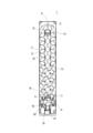
- FIG. 1 is a perspective view showing an embodiment of a work stocker.
- FIG. 2 is an internal plan view showing one embodiment of a work stocker.
- FIG. This is a cross section taken at a straight portion on one side of a roller chain that is stretched around in an oval shape, at the reversal point where the sprocket is located.
- FIG. 4 is a perspective view showing the workpiece transport table from below.
- FIG. 1 is a plan view showing an image of a work stocker equipped with work transport tables of different sizes.
- FIG. 11 is a flowchart showing a workpiece transport process according to a workpiece transport program.
- Figs. 1 and 2 show one embodiment of a work stocker, with Fig. 1 being a perspective view and Fig. 2 being an internal plan view.
- the work stocker 1 of this embodiment is installed in a machining line in which multiple machine tools and the like are arranged side-by-side, and functions as a work supply device that supplies workpieces in the machining line, and as a work recovery device that recovers machined workpieces.
- the work stocker 1 is entirely covered by an exterior cover 2, within which a work transport mechanism 5 is configured.
- the work transport mechanism 5 has multiple work transport tables 3 on which workpieces can be stacked, and is configured to position the corresponding work transport table 3 at the work transfer position P.
- 18 work transport tables 3 are arranged in a row on an elliptical track, connected by an endless roller chain 13 shown by the dashed line in Figure 2, and configured to move simultaneously in the circumferential direction and stop at a predetermined position.
- a pair of sprockets 15, 16 are supported at the front and rear of the work stocker 1, with a roller chain 13 stretched across them.
- a drive motor 14 is connected to the sprocket 15 on the rear side of the machine body, and the drive control rotates the roller chain 13 a specified amount in a specified direction, so that the 18 work transport tables 3 move all at once.
- the turn-around position of the sprocket 16 of the work stocker 1 becomes the work transfer position P, and multiple workpieces stacked on the work transport table 3 are transported out by an autoloader, or processed workpieces are transported in.
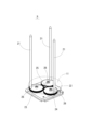
- Figure 3 is a perspective view showing the work transport table 3.
- the work transport table 3 has three guide rods 21 that are inserted vertically through the pallet 11.
- Three slits 22 are formed radially at intervals of 120 degrees in the disk-shaped pallet 11, and the three guide rods 21 are erected so as to pass through the three slits 22.
- These three guide rods 21 can be adjusted radially to match the size of the work by moving within the slits 22.
- the workpiece transport table 3 has one transmission gear 25 journaled on a base plate 23, which in turn engages with three adjustment gears 26 journaled around it.
- the pallet 11 is positioned so that its center overlaps with the center of rotation of the transmission gear 25, and the three adjustment gears 26 are positioned so that their centers of rotation are spaced 120 degrees apart from the central transmission gear 25.
- Guide rods 21, each aligned with the three adjustment gears 26, are fixed in a vertically upright position.
- the position of the work transport table 3 can be adjusted by the worker by moving the guide rods 21 radially along the slits 22. That is, the three adjustment gears 26 rotate simultaneously by the same angle via the transmission gear 25, and accordingly the three guide rods move radially the same distance simultaneously. Therefore, by adjusting the work transport table 3 by the worker, the three guide rods 21 protruding from the pallet 11 are positioned on the same circumference according to the size of the work. In this way, the work stocker 1 is able to accommodate workpieces of various sizes.
- the work stocker 1 shown in Figures 1 and 2 has 18 work transport tables 3 connected to the endless roller chain 13, but this affects the size of the pallet 11. Therefore, if the pallet 11 could be made smaller, it would be possible to connect even more work transport tables 3 to a roller chain 13 of the same length. In other words, the amount of workpieces that can be loaded on the work stocker 1 can be increased.
- FIGS. 4 and 5 are cross-sectional views showing the replacement structure of the work transport table 3.
- Figure 4 is a cross-section cut at a straight portion on one side of the roller chain 13 that is hung in an oval shape at the reversal point where the sprocket 15 (16) is located.
- Figure 5 is a cross-sectional view of the work transport table 3.
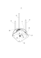
- Figure 6 is an oblique view showing the work transport table 3 from below.
- the roller chain 13 is composed of inner links 51 and outer links 52 connected alternately.
- the inner links 51 are roller links, with two hollow bushings pressed between the two inner plates, and hollow rollers fitted to the outside of each bushing.
- the outer links 52 are pin links, with two connecting pins 55 pressed into the two outer plates.
- the connecting pins 55 pass through the bushings of the inner links 51, connecting the inner links 51 and outer links 52 alternately to form the roller chain 13.
- the roller chain 13 of this embodiment in particular uses hollow connecting pins 55, which serve as positioning holes for the work transport table 3.
- the workpiece transport table 3 has a lower plate 24 stacked on the underside of a base plate 23, and two mounting pins 27 fixed to the base plate 23 so as to protrude downward from the lower plate 24.
- the spacing between the two mounting pins 27 is matched to the spacing between the two connecting pins 55 of the outer link 52 that constitutes the roller chain 13, and they are formed with a thickness that allows them to be inserted into the pipe-shaped connecting pins 55.
- the two mounting pins 27 are also formed so that they are positioned closer to the roller chain 13 than the transmission gear 25, which is located in the center.
- the work stocker 1 is configured so that the work transport table 3, which moves while being pulled by the roller chain 13, has its lower plate 24 supported by the support rollers 17 as shown in FIG. 5.
- a plurality of support rollers 17 are arranged along the roller chain 13, at the outer position of the oval shown in the figure, and at the inner position of the oval, which is omitted in the figure. Therefore, the work transport table 3, which moves in the circumferential direction, is pulled by the roller chain 13 via the mounting pins 27, and while being supported by the support rollers 17, moves while the base plate 23 maintains a horizontal position.
- the work stocker 1 is provided with multiple types of work transport tables 3 of different sizes depending on the size of the work.
- Figure 7 is a plan view showing an image of a work stocker equipped with such work transport tables 3 of different sizes.
- the drawing shows two types of work transport tables 3 of different sizes (31, 33).
- the different sized work transport tables 31, 33, etc. provided for the work stocker 1 all have the same configuration as the work transport table 3 shown in Figure 3, etc., and the base plate 23 and adjustment gear 26 are designed according to the diameter of the pallet 11.
- the position of the mounting pins 27 and the size of the lower plate of the work transport tables 31, 33, etc. are designed so that the lower plate rests on the support rollers 17.
- the work transport tables 31, 33, etc. have two common mounting pins 27 that can be inserted into the connecting pin 55 of the outer link 52. Therefore, the work stocker 1 allows the work transport table 3 (31, 33, etc.) to be selected according to the size of the work, and any combination is possible within the range of the length of the roller chain 13.
- the work stocker 1 is configured with a pallet lifting device 18 at the work transfer position P.
- the pallet lifting device 18 has a vertical support pillar 41 fixed to the front of the machine body, and a lifting platform 42 attached to a slide rail formed on the pillar.
- a bifurcated support plate 43 that supports the pallet 11 from below is fixed to the lifting platform 42, and an elevator that moves the lifting platform 42 up and down is provided inside the pillar 41.
- the lifting platform 42 is fixed to a lifting chain that is hung between upper and lower sprockets, and the height of the lifting platform 42 is adjusted by driving a lifting motor connected to one of the sprockets.
- the work stocker 1 In conventional work stockers, all the same work transport tables are arranged at equal intervals, so positioning at the work transfer position P can be controlled by detecting the rotation angle of the drive motor with a proximity switch.
- a work stocker 1 capable of mounting work transport tables 3 of different sizes, as in this embodiment, it is difficult to accurately stop the work transport table at the work transfer position P using conventional drive control. Therefore, as shown in Figure 6, the work stocker 1 is configured such that a dog 35, which is the object to be detected, is fixed to the lower plate 24 of each work transport table 3, and a specific work transport table 3 is stopped at a set position by detecting this.
- the work stocker 1 requires accurate stopping control to stop the work transport table 3 at the work transfer position P and reliably raise and lower the pallet 11. Therefore, as shown in FIG. 7, deceleration proximity switches 37 and 39 are provided on either side of the stop proximity switch 38 at the work transfer position P, and the dog 35 is detected at each position.
- the control device 6, which controls the drive of the work stocker 1, stores a work transport program for controlling the drive of the drive motor 14 in response to the detection signal from the stop proximity switch 38 or the deceleration proximity switches 37 and 39.
- the control device 6 includes a work transport table 3 (31, 33, etc.) mounted on the work stocker 1. Information regarding the number and arrangement (position number, etc.) of the workpieces is input, and a predetermined workpiece (workpiece conveying table 3) is selected according to the machining program in the machining line. Therefore, in response to a workpiece conveying command from the machining program, a corresponding one of the multiple workpiece conveying tables 3 is sent to the workpiece delivery position P. At that time, in the workpiece conveying program, based on the workpiece conveying command, the workpiece conveying tables 3 simply move one by one to the next, or move several at a time, or such movement is performed by changing the rotation direction.
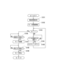
- FIG. 8 is a flow chart showing the work transport process by the work transport program.
- the movement information is information for the corresponding work transport table 3 to move the shortest distance to the work transfer position P, and the rotation direction of the roller chain 13 (drive motor 14) and the number of the work transport table 3 in that rotation direction are obtained from the count number N.
- rotation control of the drive motor 14 in the specified direction is started (S102).
- the count number N is checked to determine which work transport table 3 is in question (S103). That is, by checking whether the count number N is "1", a determination is made as to whether the next work transport table 3 moving to the work transfer position P will be the target of detection by the stop proximity switch 38. If the count number N is not "1" (S103: NO), the detection signal of the stop proximity switch 38 is ignored in order to allow the inapplicable work transport table 3 to pass, and the count number N is counted down by "1" according to the detection signals of the two deceleration proximity switches 37, 39 (S104: YES) (S105).
- the detection signal transmitted by the deceleration proximity switch 37 (or 39) upon detection of the dog 35 is confirmed (S106). Then, deceleration control of the drive motor 14 is performed in accordance with the detection signal, and the moving speed of the work transport table 3 decreases just before the work transfer position P (S106: YES, S107). Next, the detection signal transmitted by the stop proximity switch 38 upon detection of the dog 35 is confirmed (S106). Then, stop control of the drive motor 14 is performed in accordance with the detection signal, and the work transport table 3 stops at the work transfer position P (S108: YES, S109), and the work transport process ends.
- the work transport table 3 can be attached and detached, it is easy to replace a work transport table 3 that needs to be replaced due to a malfunction or the like. Also, by providing work transport tables 3 of different sizes, the number of workpieces that can be mounted can be increased in the case of small workpieces. In the example shown in FIG. 7, only ten large work transport tables 31 can be attached to the roller chain 13, but by replacing half of these, or five of them, ten small work transport tables 33 can be attached. In other words, twice as many small workpieces can be mounted on the work stocker 1 compared to when only the work transport tables 31 are used.
- the workpiece transport table 3 can be removed simply by inserting the mounting pin 27 into the roller chain 13, making replacement extremely simple.
- the configuration of the workpiece transport table 3 and other components does not require significant changes compared to conventional configurations, so the above effects can be achieved by making minor improvements to conventional workpiece stockers.
- Furthermore, for positioning control to stop the workpiece at the workpiece transfer position P it is only necessary to add a small amount of configuration, such as the dog 35, the stop proximity switch 38, the deceleration proximity switches 37 and 39, and the workpiece transport program.
- the dog 35 is detected by the stop proximity switch 38 and the deceleration proximity switches 37, 39, and the stop control of the work transport table 3 at the work transfer position P is performed, but the stop control may be performed by a different configuration.
- Reference Signs List 1 Work stocker 3 (31, 33): Work transport table 5: Work transport mechanism 6: Control device 11: Pallet 13: Roller chain 14: Drive motor 15, 16: Sprocket 18: Pallet lifting device 21: Guide rod 23: Base plate 27: Mounting pin 35: Dog 37, 39: Deceleration proximity switch 38: Stop proximity switch 51: Inner link 52: Outer link 55: Connecting pin P: Work transfer position
Landscapes
- Engineering & Computer Science (AREA)
- Mechanical Engineering (AREA)
- Feeding Of Workpieces (AREA)
Abstract
La présente invention concerne un dispositif de stockage de pièces avec des tables de transfert de pièces remplaçables. L'invention concerne un dispositif de stockage de pièces avec une palette remplaçable (11), le dispositif de stockage de pièces comprenant : une chaîne à rouleaux (13) enroulée en forme ovale autour de deux pignons; un moteur d'entraînement qui fait tourner l'un des pignons ; et une pluralité de tables de transfert de pièces (3) alignées dans la direction circonférentielle et montées sur la chaîne à rouleaux ; et un dispositif de commande qui amène une table de transfert de pièces désignée parmi les tables de transfert de pièces, qui se déplacent ensemble par commande du moteur d'entraînement, à s'arrêter à une position définie. Entre les tables de transfert de pièces et la chaîne à rouleaux, une section d'attache/séparation est configurée pour permettre une séparation des tables de transfert de pièces de la chaîne à rouleaux. Par exemple, la section d'attache/séparation est configurée de telle sorte que des goupilles d'accouplement (55) qui accouplent un maillon externe (52) et un maillon interne (51) constituant la chaîne à rouleaux sont de forme creuse, et les tables de transfert de pièces ont, formées sur celles-ci, des goupilles de montage (27) qui peuvent être insérées dans les goupilles d'accouplement.
Priority Applications (1)
| Application Number | Priority Date | Filing Date | Title |
|---|---|---|---|
| PCT/JP2023/030073 WO2025041245A1 (fr) | 2023-08-22 | 2023-08-22 | Dispositif de stockage de pièces |
Applications Claiming Priority (1)
| Application Number | Priority Date | Filing Date | Title |
|---|---|---|---|
| PCT/JP2023/030073 WO2025041245A1 (fr) | 2023-08-22 | 2023-08-22 | Dispositif de stockage de pièces |
Publications (1)
| Publication Number | Publication Date |
|---|---|
| WO2025041245A1 true WO2025041245A1 (fr) | 2025-02-27 |
Family
ID=94731832
Family Applications (1)
| Application Number | Title | Priority Date | Filing Date |
|---|---|---|---|
| PCT/JP2023/030073 Pending WO2025041245A1 (fr) | 2023-08-22 | 2023-08-22 | Dispositif de stockage de pièces |
Country Status (1)
| Country | Link |
|---|---|
| WO (1) | WO2025041245A1 (fr) |
Citations (8)
| Publication number | Priority date | Publication date | Assignee | Title |
|---|---|---|---|---|
| JPS52140396U (fr) * | 1976-04-19 | 1977-10-24 | ||
| JPS63169255A (ja) * | 1986-12-27 | 1988-07-13 | Tsudakoma Ind Co Ltd | 自動パレツト交換装置のキヤリア移送方法 |
| JPS63113534U (fr) * | 1987-01-14 | 1988-07-21 | ||
| JPH09300159A (ja) * | 1996-05-17 | 1997-11-25 | Okuma Mach Works Ltd | ワークテーブル |
| JPH10234551A (ja) * | 1997-02-24 | 1998-09-08 | Ishino Seisakusho:Kk | 載置台を有するローラチェーンコンベヤ |
| JP2012012124A (ja) * | 2010-06-29 | 2012-01-19 | Taisei Corp | バケットリフタ |
| JP2014507357A (ja) * | 2011-02-03 | 2014-03-27 | フアビオ・ペリニ・ソシエタ・ペル・アチオーニ | ペーパーロール又は他の細長い製品用アキュムレータ及びその構成方法 |
| JP2023076779A (ja) * | 2021-11-23 | 2023-06-02 | 株式会社Fuji | ワークストッカ |
-
2023
- 2023-08-22 WO PCT/JP2023/030073 patent/WO2025041245A1/fr active Pending
Patent Citations (8)
| Publication number | Priority date | Publication date | Assignee | Title |
|---|---|---|---|---|
| JPS52140396U (fr) * | 1976-04-19 | 1977-10-24 | ||
| JPS63169255A (ja) * | 1986-12-27 | 1988-07-13 | Tsudakoma Ind Co Ltd | 自動パレツト交換装置のキヤリア移送方法 |
| JPS63113534U (fr) * | 1987-01-14 | 1988-07-21 | ||
| JPH09300159A (ja) * | 1996-05-17 | 1997-11-25 | Okuma Mach Works Ltd | ワークテーブル |
| JPH10234551A (ja) * | 1997-02-24 | 1998-09-08 | Ishino Seisakusho:Kk | 載置台を有するローラチェーンコンベヤ |
| JP2012012124A (ja) * | 2010-06-29 | 2012-01-19 | Taisei Corp | バケットリフタ |
| JP2014507357A (ja) * | 2011-02-03 | 2014-03-27 | フアビオ・ペリニ・ソシエタ・ペル・アチオーニ | ペーパーロール又は他の細長い製品用アキュムレータ及びその構成方法 |
| JP2023076779A (ja) * | 2021-11-23 | 2023-06-02 | 株式会社Fuji | ワークストッカ |
Similar Documents
| Publication | Publication Date | Title |
|---|---|---|
| US6912774B2 (en) | Apparatus and method for assembly of motorcycle frame | |
| CN103964171B (zh) | 一种输送装置 | |
| KR101573485B1 (ko) | 단차 측정 자동화장치 | |
| CN101480118B (zh) | 表面安装机 | |
| KR101849351B1 (ko) | 듀얼 기판 소팅장치 및 방법 | |
| WO2025041245A1 (fr) | Dispositif de stockage de pièces | |
| JP6374344B2 (ja) | 搬送方法及び搬送システム | |
| DE10147319A1 (de) | Vorrichtung zum Austauschen von Werkstücken | |
| CN112660747A (zh) | 一种收料设备 | |
| JP2017048010A (ja) | 搬送装置 | |
| CN109051599A (zh) | 一种随行工装板的自动定位装置 | |
| JP2008126392A (ja) | ワーク供給装置 | |
| CN116443496A (zh) | 一种链式环型储料装置及操作方法 | |
| CN222711368U (zh) | 一种电磁阀底滤网上料及装配装置 | |
| CN220333783U (zh) | 自动输送装置及自动生产线 | |
| CN223519219U (zh) | 机床连线设备 | |
| JP2748288B2 (ja) | パレット位置決め装置 | |
| JP7818729B1 (ja) | 支持ベース | |
| CN219092806U (zh) | 一种精密紧固件分选设备 | |
| JP7141662B2 (ja) | ガラス板の孔開け装置 | |
| KR200293092Y1 (ko) | 자동차용 시트레일 조립기의 소재 이송장치 | |
| KR101421434B1 (ko) | 소재 공급 및 셋팅이 용이한 플라즈마 절단장치 | |
| KR100403828B1 (ko) | 엘이디용 전자부품 케이스 자동정렬장치 및 그 방법 | |
| KR101240546B1 (ko) | 장방형 구조로 배열된 전자 부품의 이동 방법 및 장치 | |
| JP2784307B2 (ja) | 自動加工方法および装置 |
Legal Events
| Date | Code | Title | Description |
|---|---|---|---|
| 121 | Ep: the epo has been informed by wipo that ep was designated in this application |
Ref document number: 23949706 Country of ref document: EP Kind code of ref document: A1 |
|
| NENP | Non-entry into the national phase |
Ref country code: DE |