WO2025041245A1 - Workpiece stocker - Google Patents
Workpiece stocker Download PDFInfo
- Publication number
- WO2025041245A1 WO2025041245A1 PCT/JP2023/030073 JP2023030073W WO2025041245A1 WO 2025041245 A1 WO2025041245 A1 WO 2025041245A1 JP 2023030073 W JP2023030073 W JP 2023030073W WO 2025041245 A1 WO2025041245 A1 WO 2025041245A1
- Authority
- WO
- WIPO (PCT)
- Prior art keywords
- work
- roller chain
- work transport
- transport table
- stocker
- Prior art date
- Legal status (The legal status is an assumption and is not a legal conclusion. Google has not performed a legal analysis and makes no representation as to the accuracy of the status listed.)
- Pending
Links
Images


Classifications
-
- B—PERFORMING OPERATIONS; TRANSPORTING
- B23—MACHINE TOOLS; METAL-WORKING NOT OTHERWISE PROVIDED FOR
- B23Q—DETAILS, COMPONENTS, OR ACCESSORIES FOR MACHINE TOOLS, e.g. ARRANGEMENTS FOR COPYING OR CONTROLLING; MACHINE TOOLS IN GENERAL CHARACTERISED BY THE CONSTRUCTION OF PARTICULAR DETAILS OR COMPONENTS; COMBINATIONS OR ASSOCIATIONS OF METAL-WORKING MACHINES, NOT DIRECTED TO A PARTICULAR RESULT
- B23Q7/00—Arrangements for handling work specially combined with or arranged in, or specially adapted for use in connection with, machine tools, e.g. for conveying, loading, positioning, discharging, sorting
- B23Q7/03—Arrangements for handling work specially combined with or arranged in, or specially adapted for use in connection with, machine tools, e.g. for conveying, loading, positioning, discharging, sorting by means of endless chain conveyors
-
- B—PERFORMING OPERATIONS; TRANSPORTING
- B65—CONVEYING; PACKING; STORING; HANDLING THIN OR FILAMENTARY MATERIAL
- B65G—TRANSPORT OR STORAGE DEVICES, e.g. CONVEYORS FOR LOADING OR TIPPING, SHOP CONVEYOR SYSTEMS OR PNEUMATIC TUBE CONVEYORS
- B65G17/00—Conveyors having an endless traction element, e.g. a chain, transmitting movement to a continuous or substantially-continuous load-carrying surface or to a series of individual load-carriers; Endless-chain conveyors in which the chains form the load-carrying surface
- B65G17/30—Details; Auxiliary devices
- B65G17/38—Chains or like traction elements; Connections between traction elements and load-carriers
- B65G17/42—Attaching load carriers to traction elements
Definitions
- a work stocker In automatic machining on machine tools, a work stocker is used to load multiple workpieces and transport them in sequence to a predetermined position to supply them to the machine tool.
- a conventional work stocker is disclosed in Patent Document 1 below.
- an endless chain is hung on a pair of sprockets on a table, and multiple work transport tables are connected to the endless chain.
- the multiple work transport tables are then moved simultaneously in the circumferential direction by the drive control of the work stocker, and the corresponding work transport table is positioned at the transfer position of, for example, an autoloader.
- Work stockers are used to mount a variety of workpieces to be processed by machine tools, and these workpieces vary in size.
- Conventional work stockers used the same work transport table for the same pallet to accommodate small to large workpieces, so the pallet was designed to accommodate the largest workpiece.
- the work transport table designed to accommodate the largest workpiece was capable of mounting all workpieces, it was not possible to increase the total number of workpieces that could be mounted on the work stocker when small workpieces were to be processed. In other words, the larger the pallet, the fewer the number of work transport tables that could be attached to the work stocker, and accordingly there was a limit to the number of workpieces that could be mounted.
- the present invention aims to solve this problem by providing a work stocker that allows the work transport table to be replaced.
- the work stocker comprises a roller chain stretched around two sprockets in an oval shape, a drive motor that rotates one of the sprockets, a number of work transport tables attached in a line circumferentially to the roller chain, and a control device that stops a relevant one of the work transport tables moving in unison at a set position by controlling the drive motor, and a detachable section is configured between the work transport table and the roller chain that allows the work transport table to be removed from the roller chain.
- the roller chain is rotated by the control of the drive motor by the control device, and the multiple work transport tables attached to it move in a line in the circumferential direction, and the relevant work from among them stops at a set position, for example, where the work is loaded or unloaded.
- a detachable attachment/detachment part is configured between the work transport table and the roller chain, and the work transport table can be removed from the roller chain, so that it is possible to replace, for example, a work transport table that needs to be replaced due to a malfunction, or a work transport table that matches the size of the work.
- FIG. 1 is a perspective view showing an embodiment of a work stocker.
- FIG. 2 is an internal plan view showing one embodiment of a work stocker.
- FIG. This is a cross section taken at a straight portion on one side of a roller chain that is stretched around in an oval shape, at the reversal point where the sprocket is located.
- FIG. 4 is a perspective view showing the workpiece transport table from below.
- FIG. 1 is a plan view showing an image of a work stocker equipped with work transport tables of different sizes.
- FIG. 11 is a flowchart showing a workpiece transport process according to a workpiece transport program.
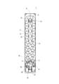
- Figs. 1 and 2 show one embodiment of a work stocker, with Fig. 1 being a perspective view and Fig. 2 being an internal plan view.
- the work stocker 1 of this embodiment is installed in a machining line in which multiple machine tools and the like are arranged side-by-side, and functions as a work supply device that supplies workpieces in the machining line, and as a work recovery device that recovers machined workpieces.
- the work stocker 1 is entirely covered by an exterior cover 2, within which a work transport mechanism 5 is configured.
- the work transport mechanism 5 has multiple work transport tables 3 on which workpieces can be stacked, and is configured to position the corresponding work transport table 3 at the work transfer position P.
- 18 work transport tables 3 are arranged in a row on an elliptical track, connected by an endless roller chain 13 shown by the dashed line in Figure 2, and configured to move simultaneously in the circumferential direction and stop at a predetermined position.
- a pair of sprockets 15, 16 are supported at the front and rear of the work stocker 1, with a roller chain 13 stretched across them.
- a drive motor 14 is connected to the sprocket 15 on the rear side of the machine body, and the drive control rotates the roller chain 13 a specified amount in a specified direction, so that the 18 work transport tables 3 move all at once.
- the turn-around position of the sprocket 16 of the work stocker 1 becomes the work transfer position P, and multiple workpieces stacked on the work transport table 3 are transported out by an autoloader, or processed workpieces are transported in.
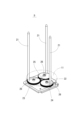
- Figure 3 is a perspective view showing the work transport table 3.
- the work transport table 3 has three guide rods 21 that are inserted vertically through the pallet 11.
- Three slits 22 are formed radially at intervals of 120 degrees in the disk-shaped pallet 11, and the three guide rods 21 are erected so as to pass through the three slits 22.
- These three guide rods 21 can be adjusted radially to match the size of the work by moving within the slits 22.
- the workpiece transport table 3 has one transmission gear 25 journaled on a base plate 23, which in turn engages with three adjustment gears 26 journaled around it.
- the pallet 11 is positioned so that its center overlaps with the center of rotation of the transmission gear 25, and the three adjustment gears 26 are positioned so that their centers of rotation are spaced 120 degrees apart from the central transmission gear 25.
- Guide rods 21, each aligned with the three adjustment gears 26, are fixed in a vertically upright position.
- the position of the work transport table 3 can be adjusted by the worker by moving the guide rods 21 radially along the slits 22. That is, the three adjustment gears 26 rotate simultaneously by the same angle via the transmission gear 25, and accordingly the three guide rods move radially the same distance simultaneously. Therefore, by adjusting the work transport table 3 by the worker, the three guide rods 21 protruding from the pallet 11 are positioned on the same circumference according to the size of the work. In this way, the work stocker 1 is able to accommodate workpieces of various sizes.
- the work stocker 1 shown in Figures 1 and 2 has 18 work transport tables 3 connected to the endless roller chain 13, but this affects the size of the pallet 11. Therefore, if the pallet 11 could be made smaller, it would be possible to connect even more work transport tables 3 to a roller chain 13 of the same length. In other words, the amount of workpieces that can be loaded on the work stocker 1 can be increased.
- FIGS. 4 and 5 are cross-sectional views showing the replacement structure of the work transport table 3.
- Figure 4 is a cross-section cut at a straight portion on one side of the roller chain 13 that is hung in an oval shape at the reversal point where the sprocket 15 (16) is located.
- Figure 5 is a cross-sectional view of the work transport table 3.
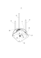
- Figure 6 is an oblique view showing the work transport table 3 from below.
- the roller chain 13 is composed of inner links 51 and outer links 52 connected alternately.
- the inner links 51 are roller links, with two hollow bushings pressed between the two inner plates, and hollow rollers fitted to the outside of each bushing.
- the outer links 52 are pin links, with two connecting pins 55 pressed into the two outer plates.
- the connecting pins 55 pass through the bushings of the inner links 51, connecting the inner links 51 and outer links 52 alternately to form the roller chain 13.
- the roller chain 13 of this embodiment in particular uses hollow connecting pins 55, which serve as positioning holes for the work transport table 3.
- the workpiece transport table 3 has a lower plate 24 stacked on the underside of a base plate 23, and two mounting pins 27 fixed to the base plate 23 so as to protrude downward from the lower plate 24.
- the spacing between the two mounting pins 27 is matched to the spacing between the two connecting pins 55 of the outer link 52 that constitutes the roller chain 13, and they are formed with a thickness that allows them to be inserted into the pipe-shaped connecting pins 55.
- the two mounting pins 27 are also formed so that they are positioned closer to the roller chain 13 than the transmission gear 25, which is located in the center.
- the work stocker 1 is configured so that the work transport table 3, which moves while being pulled by the roller chain 13, has its lower plate 24 supported by the support rollers 17 as shown in FIG. 5.
- a plurality of support rollers 17 are arranged along the roller chain 13, at the outer position of the oval shown in the figure, and at the inner position of the oval, which is omitted in the figure. Therefore, the work transport table 3, which moves in the circumferential direction, is pulled by the roller chain 13 via the mounting pins 27, and while being supported by the support rollers 17, moves while the base plate 23 maintains a horizontal position.
- the work stocker 1 is provided with multiple types of work transport tables 3 of different sizes depending on the size of the work.
- Figure 7 is a plan view showing an image of a work stocker equipped with such work transport tables 3 of different sizes.
- the drawing shows two types of work transport tables 3 of different sizes (31, 33).
- the different sized work transport tables 31, 33, etc. provided for the work stocker 1 all have the same configuration as the work transport table 3 shown in Figure 3, etc., and the base plate 23 and adjustment gear 26 are designed according to the diameter of the pallet 11.
- the position of the mounting pins 27 and the size of the lower plate of the work transport tables 31, 33, etc. are designed so that the lower plate rests on the support rollers 17.
- the work transport tables 31, 33, etc. have two common mounting pins 27 that can be inserted into the connecting pin 55 of the outer link 52. Therefore, the work stocker 1 allows the work transport table 3 (31, 33, etc.) to be selected according to the size of the work, and any combination is possible within the range of the length of the roller chain 13.
- the work stocker 1 is configured with a pallet lifting device 18 at the work transfer position P.
- the pallet lifting device 18 has a vertical support pillar 41 fixed to the front of the machine body, and a lifting platform 42 attached to a slide rail formed on the pillar.
- a bifurcated support plate 43 that supports the pallet 11 from below is fixed to the lifting platform 42, and an elevator that moves the lifting platform 42 up and down is provided inside the pillar 41.
- the lifting platform 42 is fixed to a lifting chain that is hung between upper and lower sprockets, and the height of the lifting platform 42 is adjusted by driving a lifting motor connected to one of the sprockets.
- the work stocker 1 In conventional work stockers, all the same work transport tables are arranged at equal intervals, so positioning at the work transfer position P can be controlled by detecting the rotation angle of the drive motor with a proximity switch.
- a work stocker 1 capable of mounting work transport tables 3 of different sizes, as in this embodiment, it is difficult to accurately stop the work transport table at the work transfer position P using conventional drive control. Therefore, as shown in Figure 6, the work stocker 1 is configured such that a dog 35, which is the object to be detected, is fixed to the lower plate 24 of each work transport table 3, and a specific work transport table 3 is stopped at a set position by detecting this.
- the work stocker 1 requires accurate stopping control to stop the work transport table 3 at the work transfer position P and reliably raise and lower the pallet 11. Therefore, as shown in FIG. 7, deceleration proximity switches 37 and 39 are provided on either side of the stop proximity switch 38 at the work transfer position P, and the dog 35 is detected at each position.
- the control device 6, which controls the drive of the work stocker 1, stores a work transport program for controlling the drive of the drive motor 14 in response to the detection signal from the stop proximity switch 38 or the deceleration proximity switches 37 and 39.
- the control device 6 includes a work transport table 3 (31, 33, etc.) mounted on the work stocker 1. Information regarding the number and arrangement (position number, etc.) of the workpieces is input, and a predetermined workpiece (workpiece conveying table 3) is selected according to the machining program in the machining line. Therefore, in response to a workpiece conveying command from the machining program, a corresponding one of the multiple workpiece conveying tables 3 is sent to the workpiece delivery position P. At that time, in the workpiece conveying program, based on the workpiece conveying command, the workpiece conveying tables 3 simply move one by one to the next, or move several at a time, or such movement is performed by changing the rotation direction.
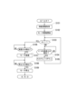
- FIG. 8 is a flow chart showing the work transport process by the work transport program.
- the movement information is information for the corresponding work transport table 3 to move the shortest distance to the work transfer position P, and the rotation direction of the roller chain 13 (drive motor 14) and the number of the work transport table 3 in that rotation direction are obtained from the count number N.
- rotation control of the drive motor 14 in the specified direction is started (S102).
- the count number N is checked to determine which work transport table 3 is in question (S103). That is, by checking whether the count number N is "1", a determination is made as to whether the next work transport table 3 moving to the work transfer position P will be the target of detection by the stop proximity switch 38. If the count number N is not "1" (S103: NO), the detection signal of the stop proximity switch 38 is ignored in order to allow the inapplicable work transport table 3 to pass, and the count number N is counted down by "1" according to the detection signals of the two deceleration proximity switches 37, 39 (S104: YES) (S105).
- the detection signal transmitted by the deceleration proximity switch 37 (or 39) upon detection of the dog 35 is confirmed (S106). Then, deceleration control of the drive motor 14 is performed in accordance with the detection signal, and the moving speed of the work transport table 3 decreases just before the work transfer position P (S106: YES, S107). Next, the detection signal transmitted by the stop proximity switch 38 upon detection of the dog 35 is confirmed (S106). Then, stop control of the drive motor 14 is performed in accordance with the detection signal, and the work transport table 3 stops at the work transfer position P (S108: YES, S109), and the work transport process ends.
- the work transport table 3 can be attached and detached, it is easy to replace a work transport table 3 that needs to be replaced due to a malfunction or the like. Also, by providing work transport tables 3 of different sizes, the number of workpieces that can be mounted can be increased in the case of small workpieces. In the example shown in FIG. 7, only ten large work transport tables 31 can be attached to the roller chain 13, but by replacing half of these, or five of them, ten small work transport tables 33 can be attached. In other words, twice as many small workpieces can be mounted on the work stocker 1 compared to when only the work transport tables 31 are used.
- the workpiece transport table 3 can be removed simply by inserting the mounting pin 27 into the roller chain 13, making replacement extremely simple.
- the configuration of the workpiece transport table 3 and other components does not require significant changes compared to conventional configurations, so the above effects can be achieved by making minor improvements to conventional workpiece stockers.
- Furthermore, for positioning control to stop the workpiece at the workpiece transfer position P it is only necessary to add a small amount of configuration, such as the dog 35, the stop proximity switch 38, the deceleration proximity switches 37 and 39, and the workpiece transport program.
- the dog 35 is detected by the stop proximity switch 38 and the deceleration proximity switches 37, 39, and the stop control of the work transport table 3 at the work transfer position P is performed, but the stop control may be performed by a different configuration.
- Reference Signs List 1 Work stocker 3 (31, 33): Work transport table 5: Work transport mechanism 6: Control device 11: Pallet 13: Roller chain 14: Drive motor 15, 16: Sprocket 18: Pallet lifting device 21: Guide rod 23: Base plate 27: Mounting pin 35: Dog 37, 39: Deceleration proximity switch 38: Stop proximity switch 51: Inner link 52: Outer link 55: Connecting pin P: Work transfer position
Landscapes
- Engineering & Computer Science (AREA)
- Mechanical Engineering (AREA)
- Feeding Of Workpieces (AREA)
Abstract
Description
本発明は、ワーク搬送台の取り換えが可能なワークストッカに関する。 The present invention relates to a work stocker that allows the work transport table to be replaced.
工作機械における自動加工では、ワークを複数個搭載して順番に所定位置まで搬送することにより、工作機械側へと供給するためのワークストッカが用いられている。下記特許文献1には従来のワークストッカが開示されている。そのワークストッカは、テーブル上の一対のスプロケットに無端チェーンが掛けられ、その無端チェーンには複数のワーク搬送台が連結されている。そして、ワークストッカの駆動制御により複数のワーク搬送台が周方向に一斉に移動し、該当するワーク搬送台が、例えばオートローダの受け渡し位置に位置決めされる。
In automatic machining on machine tools, a work stocker is used to load multiple workpieces and transport them in sequence to a predetermined position to supply them to the machine tool. A conventional work stocker is disclosed in
ワークストッカは、工作機械で加工対象となる様々なワークが搭載されるが、そうしたワークは大きさも様々である。従来のワークストッカは、小さいワークから大きなワークに対応できるように同じパレットのワーク搬送台が使用されていたため、そのパレットが一番大きなワークに合わせたものになっていた。しかし、一番大きなワークに合わせたワーク搬送台は、全てのワークを搭載することが可能である一方で、小さいワークを加工対象とした場合には、ワークストッカ上に搭載できるワークの総数を増やすことができなかった。すなわち、パレットが大きい分だけワークストッカに取り付けられるワーク搬送台の数が少なくなってしまい、それに応じて搭載可能なワークの数にも限界があった。 Work stockers are used to mount a variety of workpieces to be processed by machine tools, and these workpieces vary in size. Conventional work stockers used the same work transport table for the same pallet to accommodate small to large workpieces, so the pallet was designed to accommodate the largest workpiece. However, while the work transport table designed to accommodate the largest workpiece was capable of mounting all workpieces, it was not possible to increase the total number of workpieces that could be mounted on the work stocker when small workpieces were to be processed. In other words, the larger the pallet, the fewer the number of work transport tables that could be attached to the work stocker, and accordingly there was a limit to the number of workpieces that could be mounted.
そこで、本発明は、かかる課題を解決すべく、ワーク搬送台の取り換えが可能なワークストッカを提供することを目的とする。 The present invention aims to solve this problem by providing a work stocker that allows the work transport table to be replaced.
本発明の一態様におけるワークストッカは、2個のスプロケットに対して長円形に掛け渡されたローラチェーンと、前記スプロケットの一つに回転を与える駆動用モータと、前記ローラチェーンに対して周方向に一列になって取り付けられた複数のワーク搬送台と、前記駆動用モータに対する制御によって一斉に移動する前記ワーク搬送台の中から該当するものを設定位置に停止させる制御装置と、を有し、前記ワーク搬送台と前記ローラチェーンとの間に、前記ローラチェーンに対する前記ワーク搬送台の取り外しが可能な着脱部が構成されたものである。 In one embodiment of the present invention, the work stocker comprises a roller chain stretched around two sprockets in an oval shape, a drive motor that rotates one of the sprockets, a number of work transport tables attached in a line circumferentially to the roller chain, and a control device that stops a relevant one of the work transport tables moving in unison at a set position by controlling the drive motor, and a detachable section is configured between the work transport table and the roller chain that allows the work transport table to be removed from the roller chain.
前記構成によれば、制御装置による駆動用モータの制御によってローラチェーンに回転が与えられ、そこに取り付けられた複数のワーク搬送台が周方向に一列になって移動し、その中から該当するワークが、例えばワークの搬入や搬出が行われる設定位置に停止する。そうしたワークストッカにおいて、ワーク搬送台とローラチェーンとの間に着脱可能な着脱部が構成され、ローラチェーンに対するワーク搬送台の取り外しが可能になっているため、例えば、故障などによって交換が必要なワーク搬送台や、ワークの大きさに合わせたワーク搬送台への取り換えが可能である。 In this configuration, the roller chain is rotated by the control of the drive motor by the control device, and the multiple work transport tables attached to it move in a line in the circumferential direction, and the relevant work from among them stops at a set position, for example, where the work is loaded or unloaded. In such a work stocker, a detachable attachment/detachment part is configured between the work transport table and the roller chain, and the work transport table can be removed from the roller chain, so that it is possible to replace, for example, a work transport table that needs to be replaced due to a malfunction, or a work transport table that matches the size of the work.
本発明に係るワークストッカの一実施形態について、図面を参照しながら以下に説明する。図1及び図2は、ワークストッカの一実施形態を示した図であり、図1は斜視図であって、図2は内部平面図である。本実施形態のワークストッカ1は、複数台の工作機械などが横並びに配置された加工機械ラインに設けられたものであり、その加工機械ラインにおいてワークを供給するワーク供給装置や、加工された加工済みワークを回収するワーク回収装置として機能する。
One embodiment of a work stocker according to the present invention will be described below with reference to the drawings. Figs. 1 and 2 show one embodiment of a work stocker, with Fig. 1 being a perspective view and Fig. 2 being an internal plan view. The
ワークストッカ1は、外装カバー2によって全体が覆われ、その中にはワーク搬送機構5が構成されている。ワーク搬送機構5は、ワークの段積みが可能な複数のワーク搬送台3を有し、該当するワーク搬送台3をワーク受渡し位置Pに位置決めするよう構成されている。本実施形態は、18台のワーク搬送台3が長円形の軌道上に一列になって配置され、図2に一点鎖線で示す無端のローラチェーン13によって連結され、周方向に一斉に移動し、所定位置で停止するよう構成されている。
The
ワークストッカ1の前部および後部には一対のスプロケット15,16が軸支され、そこにローラチェーン13が掛け渡されている。機体後方側のスプロケット15には駆動用モータ14が連結され、その駆動制御によってローラチェーン13を所定方向に所定量回転させ、18台のワーク搬送台3が一斉に移動するようになっている。そのワークストッカ1は、スプロケット16の折り返し位置がワーク受渡し位置Pとなり、ワーク搬送台3に段積みされた複数個のワークがオートローダによって搬出され、或いは加工済みワークが搬入されるようになっている。
A pair of
次に、図3は、ワーク搬送台3を示した斜視図である。ワーク搬送台3は、パレット11を貫いた3本のガイドロッド21が鉛直に突き立てられている。円盤形状のパレット11には120度の間隔で3つのスリット22が放射状に形成され、3本のガイドロッド21は3つのスリット22を突き抜けるようにして立設されている。そうした3本のガイドロッド21は、スリット22内を移動することにより、ワークの大きさに合わせた径方向の調整が可能になっている。
Next, Figure 3 is a perspective view showing the work transport table 3. The work transport table 3 has three
ワーク搬送台3は、ベースプレート23の上に1つの伝達ギヤ25が軸支され、更にその伝達ギヤ25には周りに軸支された3つの調整ギヤ26が噛み合っている。パレット11は、その中心が伝達ギヤ25の回転中心と重なるように配置され、3つの調整ギヤ26は、その回転中心が中央の伝達ギヤ25に対して120度の間隔で位置するように配置されている。そして、3つの調整ギヤ26に対してそれぞれ位置を合わせたガイドロッド21が鉛直に起立した状態で固定されている。
The workpiece transport table 3 has one
ワーク搬送台3は、作業者がガイドロッド21をスリット22に沿って径方向に移動させることにより位置調整が行えるようになっている。すなわち、3つの調整ギヤ26は伝達ギヤ25を介して同時に同じ角度だけ回転し、それに合わせて3本のガイドロッドが径方向に同時に同じ距離だけ移動する。よって、このワーク搬送台3は、作業者による調整作業により、パレット11から突き出した3本のガイドロッド21がワークの大きさに合わせて同一円周上に位置することとなる。ワークストッカ1は、こうして様々な大きさのワークに対応することが可能になっている。
The position of the work transport table 3 can be adjusted by the worker by moving the
しかし、全てが同じサイズのワーク搬送台3では、小さなワークを対象とした場合にパレット11上の空スペースが大きくなって無駄が生じてしまう。すなわち、図1及び図2に示すワークストッカ1は、無端のローラチェーン13に連結されるワーク搬送台3の数が18台であるが、それはパレット11の大きさに影響している。そのため、パレット11をより小さくすることができれば、同じ長さのローラチェーン13に対して更に多くのワーク搬送台3を連結することが可能になる。すなわち、ワークストッカ1におけるワークの搭載量を増やすことができる。
However, if all the work transport tables 3 are the same size, when small workpieces are being handled, the empty space on the
そこで、本実施形態のワークストッカ1は、ローラチェーン13に対するワーク搬送台3の取り換えが可能な構成が設けられている。図4および図5は、ワーク搬送台3の取り換え構造を示した断面図である。特に、図4は、スプロケット15(16)が位置する反転箇所であって、長円形に掛け渡されたローラチェーン13の片側直線部分にて切断した断面である。そして、図5は、ワーク搬送台3の断面図である。さらに、図6は、ワーク搬送台3を下面から示した斜視図である。
The
ローラチェーン13は、内リンク51と外リンク52とが交互に連結し合って構成されている。その内リンク51はローラリンクであって、2枚の内プレートの間に中空形状の2個のブシュが圧入され、各ブッシュの外側に中空形状のローラが嵌め合されている。また、外リンク52はピンリンクであり、2枚の外プレートに2本の連結ピン55が圧入されている。そして、連結ピン55が内リンク51のブッシュを貫通することにより、交互に内リンク51と外リンク52とが連結されてローラチェーン13が構成される。そして、特に本実施形態のローラチェーン13は、中空形状の連結ピン55が使用され、これがワーク搬送台3の位置決め穴になっている。
The
ワーク搬送台3は、ベースプレート23の下側に下プレート24が重ねられ、その下プレート24から下方に突き出るようにして、2本の取付けピン27がベースプレート23に固定されている。2本の取付けピン27の間隔は、ローラチェーン13を構成する外リンク52の2本の連結ピン55の間隔に合わせられ、パイプ形状の連結ピン55に挿入可能な太さで形成されている。そして、2本の取付けピン27は、中央に位置する伝達ギヤ25よりもローラチェーン13側に位置するように形成されている。
The workpiece transport table 3 has a
また、ワークストッカ1は、ローラチェーン13に引かれて移動するワーク搬送台3が、図5に示すように、下プレート24が支持ローラ17によって支えられるようになっている。支持ローラ17は、ローラチェーン13に沿うようにして、図示する長円形の外側位置と、図面では省略した長円形の内側位置とにそれぞれ複数配置されている。従って、周方向に移動するワーク搬送台3は、取付けピン27を介してローラチェーン13に引っ張られ、支持ローラ17によって支えられながら、ベースプレート23が水平な姿勢を保って移動する構成となっている。
In addition, the
ワークストッカ1は、ワークの大きさに応じてサイズの異なるワーク搬送台3が複数種類用意されている。図7は、そうしたサイズの異なるワーク搬送台3を搭載したワークストッカをイメージで示した平面図である。図面には大きさの異なる2種類のワーク搬送台3(31,33)が搭載されている。ワークストッカ1に対して用意された大きさの異なるワーク搬送台31,33などは、どれも図3などに示すワーク搬送台3と同じ構成であり、パレット11の径の大きさに応じてベースプレート23や調整ギヤ26などが設計されている。
The
また、ワーク搬送台31,33などは、下プレートが支持ローラ17に載るように、取付けピン27の位置や下プレートの大きさが設計されている。ただし、大きさが異なったとしても、ワーク搬送台31,33などは、2本の取付けピン27は共通であり、外リンク52の連結ピン55に挿入可能な構成となっている。従って、ワークストッカ1は、ワークの大きさに応じてワーク搬送台3(31,33など)が選択でき、ローラチェーン13の長さの範囲内で自由な組み合わせが可能になっている。
In addition, the position of the mounting pins 27 and the size of the lower plate of the work transport tables 31, 33, etc. are designed so that the lower plate rests on the
ワークストッカ1は、ワーク受渡し位置Pにパレット昇降装置18が構成されている。パレット昇降装置18は、機体前部に鉛直な支柱41が固定され、そこに形成されたスライドレールに昇降台42が組み付けられている。昇降台42は、パレット11を下から支える二股の支持プレート43が固定され、支柱41の内部には昇降台42を上下動させる昇降機が設けられている。昇降機は、上下のスプロケットに掛け渡された昇降チェーンに昇降台42が固定され、一方のスプロケットに連結された昇降用モータの駆動により昇降台42の高さ調節が行われる。
The
ところで、従来のワークストッカは、全て同一のワーク搬送台が等間隔に配置されていたため、ワーク受渡し位置Pに対する位置決めは、駆動用モータの回転角度を近接スイッチで検出した制御でよかった。しかし、本実施形態のように、大きさが異なるワーク搬送台3の搭載が可能なワークストッカ1では、従来の駆動制御ではワーク受渡し位置Pにワーク搬送台を正確に停止させることが困難である。そこで、ワークストッカ1は、図6に示すように、被検出体であるドッグ35が各ワーク搬送台3の下プレート24に固定され、それを検出することにより所定のワーク搬送台3を設定した位置に停止させる構成がとられている。
In conventional work stockers, all the same work transport tables are arranged at equal intervals, so positioning at the work transfer position P can be controlled by detecting the rotation angle of the drive motor with a proximity switch. However, in a
ワークストッカ1は、ワーク受渡し位置Pにワーク搬送台3を停止させ、パレット11の昇降を確実に行うための正確な停止制御が必要である。そこでワーク受渡し位置Pには、図7に示すように、停止用近接スイッチ38を挟んで、減速用近接スイッチ37,39が設けられ、各々の位置でドッグ35の検出が行われるようになっている。そして、ワークストッカ1の駆動を制御する制御装置6には、停止用近接スイッチ38または減速用近接スイッチ37,39からの検出信号に応じて、駆動用モータ14の駆動制御を実行するためのワーク搬送プログラムが格納されている。
The
制御装置6には、ワークストッカ1に搭載されたワーク搬送台3(31,33など)
の台数や配置(位置番号など)に関する情報が入力され、加工機械ラインにおける加工プログラムに応じて所定のワーク(ワーク搬送台3)が選択される。そのため、加工プログラムからのワーク搬送指令に応じて、複数のワーク搬送台3からから該当するものがワーク受渡し位置Pに送られる。その際、ワーク搬送プログラムでは、ワーク搬送指令に基づき、ワーク搬送台3が単純に1台ずつ隣へ移動し、または一度に数台分移動し、あるいはそうした移動が回転方向を変えて行われる。
The
Information regarding the number and arrangement (position number, etc.) of the workpieces is input, and a predetermined workpiece (workpiece conveying table 3) is selected according to the machining program in the machining line. Therefore, in response to a workpiece conveying command from the machining program, a corresponding one of the multiple workpiece conveying tables 3 is sent to the workpiece delivery position P. At that time, in the workpiece conveying program, based on the workpiece conveying command, the workpiece conveying tables 3 simply move one by one to the next, or move several at a time, or such movement is performed by changing the rotation direction.
図8は、ワーク搬送プログラムによるワーク搬送処理を示したフローチャート図である。ワーク搬送処理では先ず、ワーク搬送指令に基づいて該当するワークを搭載したワーク搬送台3について、その移動情報が求められる(S101)。移動情報とは、該当するワーク搬送台3がワーク受渡し位置Pまで最短距離で移動するための情報であって、ローラチェーン13(駆動用モータ14)の回転方向と、その回転方向における何台目のワーク搬送台3であるかがカウント数Nによって求められる。そして、駆動用モータ14の所定方向の回転制御が開始される(S102)。
FIG. 8 is a flow chart showing the work transport process by the work transport program. In the work transport process, first, movement information is obtained for the work transport table 3 on which the corresponding work is mounted based on the work transport command (S101). The movement information is information for the corresponding work transport table 3 to move the shortest distance to the work transfer position P, and the rotation direction of the roller chain 13 (drive motor 14) and the number of the work transport table 3 in that rotation direction are obtained from the count number N. Then, rotation control of the
駆動用モータ4の駆動開始後は、該当するワーク搬送台3を特定するための判断としてカウント数Nの確認が行われる(S103)。すなわち、カウント数Nが「1」か否かの確認によって、次にワーク受渡し位置Pに移動してくるワーク搬送台3が停止用近接スイッチ38の検出対称となるか否かについての判定が行われる。そこで、カウント数Nが「1」でない場合は(S103:NO)、該当しないワーク搬送台3を通過させるため、停止用近接スイッチ38の検出信号は無視され、2つの減速用近接スイッチ37,39の検出信号に従って(S104:YES)、カウント数Nについて「1」だけカウントダウンが行われる(S105)。
After the drive motor 4 starts to drive, the count number N is checked to determine which work transport table 3 is in question (S103). That is, by checking whether the count number N is "1", a determination is made as to whether the next work transport table 3 moving to the work transfer position P will be the target of detection by the
その後、ステップS103-S105に従い、駆動用モータ14の駆動によってローラチェーン13の回転が行われ、該当しないワーク搬送台3がワーク受渡し位置Pを通過する。そして、カウント数Nが「1」になったところで(S103:YES)、ワーク受渡し位置Pに達するワーク搬送台3の停止制御が行われる。
After that, in accordance with steps S103-S105, the
停止制御では、減速用近接スイッチ37(または39)がドッグ35の検出によって発信する検出信号が確認される(S106)。そして、その検出信号に従い駆動用モータ14の減速制御が行われ、ワーク搬送台3の移動速度がワーク受渡し位置Pの手前で低下する(S106:YES、S107)。次に、停止用近接スイッチ38がドッグ35の検出によって発信する検出信号が確認される(S106)。そして、その検出信号に従い駆動用モータ14の停止制御が行われ、ワーク搬送台3がワーク受渡し位置Pで停止し(S108:YES、S109)、ワーク搬送処理が終了する。
In the stop control, the detection signal transmitted by the deceleration proximity switch 37 (or 39) upon detection of the
よって、本実施形態のワークストッカ1では、ワーク搬送台3の着脱が可能であるため、故障などで交換が必要なワーク搬送台3について取り換えが容易である。また、大きさの異なるワーク搬送台3を用意することで、小さいワークの場合には搭載可能なワークの数を増やすことができる。図7に示した例では、大きいワーク搬送台31はローラチェーン13に10台しか取り付けられないが、そのうちの半分である5台を取り換えることにより、小さいワーク搬送台33を10台取り付けることができる。すなわち、ワーク搬送台31だけの場合に比べ、小さいワークをワークストッカ1に2倍の数搭載することができる。
Therefore, in the
また、ワーク搬送台3は、取付けピン27をローラチェーン13に対して挿入するだけで取り外しができるため、その交換作業が極めて簡単である。そして、ワーク搬送台3などに関する構成も、従来のものと比較して大幅な変更を必要とするわけではないので、従来のワークストッカをわずかに改良することによって前記効果を得ることができる。さらに、ワーク受渡し位置Pに停止させる位置決め制御に関しても、ドッグ35および停止用近接スイッチ38および減速用近接スイッチ37,39並びに、ワーク搬送プログラムといったわずかな構成の追加だけで良い。
The workpiece transport table 3 can be removed simply by inserting the mounting
本発明の一実施形態について説明したが、本発明はこれらに限定されるものではなく、その趣旨を逸脱しない範囲で様々な変更が可能である。
前記実施形態では、停止用近接スイッチ38および減速用近接スイッチ37,39によりドッグ35を検出し、ワーク受渡し位置Pに対するワーク搬送台3の停止制御を行うようにしたが、異なる構成によって停止制御を行うようにしてもよい。
Although one embodiment of the present invention has been described, the present invention is not limited to this embodiment, and various modifications are possible without departing from the spirit of the present invention.
In the above embodiment, the
1…ワークストッカ 3(31,33)…ワーク搬送台 5…ワーク搬送機構 6…制御装置 11…パレット 13…ローラチェーン 14…駆動用モータ 15,16…スプロケット 18…パレット昇降装置 21…ガイドロッド 23…ベースプレート 27…取付けピン 35…ドッグ 37,39…減速用近接スイッチ 38…停止用近接スイッチ 51…内リンク 52…外リンク 55…連結ピン P…ワーク受渡し位置
Reference Signs List 1: Work stocker 3 (31, 33): Work transport table 5: Work transport mechanism 6: Control device 11: Pallet 13: Roller chain 14: Drive
Claims (5)
前記スプロケットの一つに回転を与える駆動用モータと、
前記ローラチェーンに対して周方向に一列になって取り付けられた複数のワーク搬送台と、
前記駆動用モータに対する制御によって一斉に移動する前記ワーク搬送台の中から該当するものを設定位置に停止させる制御装置と、
を有し、
前記ワーク搬送台と前記ローラチェーンとの間に、前記ローラチェーンに対する前記ワーク搬送台の取り外しが可能な着脱部が構成されたワークストッカ。 A roller chain is looped around two sprockets in an oval shape;
a drive motor for imparting rotation to one of the sprockets;
A plurality of work transport tables are attached to the roller chain in a line in a circumferential direction;
a control device that stops a corresponding one of the work transport tables moving simultaneously at a set position by controlling the driving motor;
having
A work stocker having a detachable portion between the work transport table and the roller chain, the detachable portion enabling the work transport table to be detached from the roller chain.
Priority Applications (1)
| Application Number | Priority Date | Filing Date | Title |
|---|---|---|---|
| PCT/JP2023/030073 WO2025041245A1 (en) | 2023-08-22 | 2023-08-22 | Workpiece stocker |
Applications Claiming Priority (1)
| Application Number | Priority Date | Filing Date | Title |
|---|---|---|---|
| PCT/JP2023/030073 WO2025041245A1 (en) | 2023-08-22 | 2023-08-22 | Workpiece stocker |
Publications (1)
| Publication Number | Publication Date |
|---|---|
| WO2025041245A1 true WO2025041245A1 (en) | 2025-02-27 |
Family
ID=94731832
Family Applications (1)
| Application Number | Title | Priority Date | Filing Date |
|---|---|---|---|
| PCT/JP2023/030073 Pending WO2025041245A1 (en) | 2023-08-22 | 2023-08-22 | Workpiece stocker |
Country Status (1)
| Country | Link |
|---|---|
| WO (1) | WO2025041245A1 (en) |
Citations (8)
| Publication number | Priority date | Publication date | Assignee | Title |
|---|---|---|---|---|
| JPS52140396U (en) * | 1976-04-19 | 1977-10-24 | ||
| JPS63169255A (en) * | 1986-12-27 | 1988-07-13 | Tsudakoma Ind Co Ltd | Carrier transferring method for automatic pallet exchanger |
| JPS63113534U (en) * | 1987-01-14 | 1988-07-21 | ||
| JPH09300159A (en) * | 1996-05-17 | 1997-11-25 | Okuma Mach Works Ltd | Workpiece table |
| JPH10234551A (en) * | 1997-02-24 | 1998-09-08 | Ishino Seisakusho:Kk | Roller chain conveyer with platform |
| JP2012012124A (en) * | 2010-06-29 | 2012-01-19 | Taisei Corp | Bucket lifter |
| JP2014507357A (en) * | 2011-02-03 | 2014-03-27 | フアビオ・ペリニ・ソシエタ・ペル・アチオーニ | Paper roll or other elongated product accumulator and method of construction thereof |
| JP2023076779A (en) * | 2021-11-23 | 2023-06-02 | 株式会社Fuji | Workpiece stocker |
-
2023
- 2023-08-22 WO PCT/JP2023/030073 patent/WO2025041245A1/en active Pending
Patent Citations (8)
| Publication number | Priority date | Publication date | Assignee | Title |
|---|---|---|---|---|
| JPS52140396U (en) * | 1976-04-19 | 1977-10-24 | ||
| JPS63169255A (en) * | 1986-12-27 | 1988-07-13 | Tsudakoma Ind Co Ltd | Carrier transferring method for automatic pallet exchanger |
| JPS63113534U (en) * | 1987-01-14 | 1988-07-21 | ||
| JPH09300159A (en) * | 1996-05-17 | 1997-11-25 | Okuma Mach Works Ltd | Workpiece table |
| JPH10234551A (en) * | 1997-02-24 | 1998-09-08 | Ishino Seisakusho:Kk | Roller chain conveyer with platform |
| JP2012012124A (en) * | 2010-06-29 | 2012-01-19 | Taisei Corp | Bucket lifter |
| JP2014507357A (en) * | 2011-02-03 | 2014-03-27 | フアビオ・ペリニ・ソシエタ・ペル・アチオーニ | Paper roll or other elongated product accumulator and method of construction thereof |
| JP2023076779A (en) * | 2021-11-23 | 2023-06-02 | 株式会社Fuji | Workpiece stocker |
Similar Documents
| Publication | Publication Date | Title |
|---|---|---|
| US6912774B2 (en) | Apparatus and method for assembly of motorcycle frame | |
| CN103964171B (en) | A kind of conveying device | |
| KR101573485B1 (en) | Automattic step measuring device | |
| CN101480118B (en) | surface mount machine | |
| KR101849351B1 (en) | Dual substrate sorting apparatus and method | |
| WO2025041245A1 (en) | Workpiece stocker | |
| JP6374344B2 (en) | Transport method and transport system | |
| DE10147319A1 (en) | Device for exchanging workpieces | |
| CN112660747A (en) | Material collecting equipment | |
| JP2017048010A (en) | Transport device | |
| CN109051599A (en) | A kind of automatic positioning equipment for working plate of accompanying | |
| JP2008126392A (en) | Workpiece supply device | |
| CN116443496A (en) | Chained annular storage device and operation method | |
| CN222711368U (en) | A solenoid valve bottom filter feeding and assembly device | |
| CN220333783U (en) | Automatic conveying device and automatic production line | |
| CN223519219U (en) | Machine tool connecting equipment | |
| JP2748288B2 (en) | Pallet positioning device | |
| JP7818729B1 (en) | Support base | |
| CN219092806U (en) | Precise fastener sorting equipment | |
| JP7141662B2 (en) | Glass plate punching device | |
| KR200293092Y1 (en) | Meterial movement device of assembly machine for automobile seat rail | |
| KR101421434B1 (en) | Plasma cutting apparatus | |
| KR100403828B1 (en) | The method and apparatus for auto-array of electronic parts case using LED | |
| KR101240546B1 (en) | Method and device for displacing electronic components ordered in a rectangualr structure | |
| JP2784307B2 (en) | Automatic processing method and device |
Legal Events
| Date | Code | Title | Description |
|---|---|---|---|
| 121 | Ep: the epo has been informed by wipo that ep was designated in this application |
Ref document number: 23949706 Country of ref document: EP Kind code of ref document: A1 |
|
| NENP | Non-entry into the national phase |
Ref country code: DE |