WO2025018201A1 - ヒートシンク、発光モジュール及びヒートシンクの製造方法 - Google Patents
ヒートシンク、発光モジュール及びヒートシンクの製造方法 Download PDFInfo
- Publication number
- WO2025018201A1 WO2025018201A1 PCT/JP2024/024572 JP2024024572W WO2025018201A1 WO 2025018201 A1 WO2025018201 A1 WO 2025018201A1 JP 2024024572 W JP2024024572 W JP 2024024572W WO 2025018201 A1 WO2025018201 A1 WO 2025018201A1
- Authority
- WO
- WIPO (PCT)
- Prior art keywords
- heat sink
- shaped
- metal plate
- bending
- light
- Prior art date
- Legal status (The legal status is an assumption and is not a legal conclusion. Google has not performed a legal analysis and makes no representation as to the accuracy of the status listed.)
- Pending
Links
Images






Classifications
-
- F—MECHANICAL ENGINEERING; LIGHTING; HEATING; WEAPONS; BLASTING
- F21—LIGHTING
- F21S—NON-PORTABLE LIGHTING DEVICES; SYSTEMS THEREOF; VEHICLE LIGHTING DEVICES SPECIALLY ADAPTED FOR VEHICLE EXTERIORS
- F21S45/00—Arrangements within vehicle lighting devices specially adapted for vehicle exteriors, for purposes other than emission or distribution of light
- F21S45/40—Cooling of lighting devices
- F21S45/47—Passive cooling, e.g. using fins, thermal conductive elements or openings
-
- F—MECHANICAL ENGINEERING; LIGHTING; HEATING; WEAPONS; BLASTING
- F21—LIGHTING
- F21V—FUNCTIONAL FEATURES OR DETAILS OF LIGHTING DEVICES OR SYSTEMS THEREOF; STRUCTURAL COMBINATIONS OF LIGHTING DEVICES WITH OTHER ARTICLES, NOT OTHERWISE PROVIDED FOR
- F21V29/00—Protecting lighting devices from thermal damage; Cooling or heating arrangements specially adapted for lighting devices or systems
- F21V29/50—Cooling arrangements
- F21V29/60—Cooling arrangements characterised by the use of a forced flow of gas, e.g. air
- F21V29/67—Cooling arrangements characterised by the use of a forced flow of gas, e.g. air characterised by the arrangement of fans
-
- F—MECHANICAL ENGINEERING; LIGHTING; HEATING; WEAPONS; BLASTING
- F21—LIGHTING
- F21V—FUNCTIONAL FEATURES OR DETAILS OF LIGHTING DEVICES OR SYSTEMS THEREOF; STRUCTURAL COMBINATIONS OF LIGHTING DEVICES WITH OTHER ARTICLES, NOT OTHERWISE PROVIDED FOR
- F21V29/00—Protecting lighting devices from thermal damage; Cooling or heating arrangements specially adapted for lighting devices or systems
- F21V29/50—Cooling arrangements
- F21V29/70—Cooling arrangements characterised by passive heat-dissipating elements, e.g. heat-sinks
- F21V29/74—Cooling arrangements characterised by passive heat-dissipating elements, e.g. heat-sinks with fins or blades
-
- F—MECHANICAL ENGINEERING; LIGHTING; HEATING; WEAPONS; BLASTING
- F21—LIGHTING
- F21V—FUNCTIONAL FEATURES OR DETAILS OF LIGHTING DEVICES OR SYSTEMS THEREOF; STRUCTURAL COMBINATIONS OF LIGHTING DEVICES WITH OTHER ARTICLES, NOT OTHERWISE PROVIDED FOR
- F21V29/00—Protecting lighting devices from thermal damage; Cooling or heating arrangements specially adapted for lighting devices or systems
- F21V29/50—Cooling arrangements
- F21V29/70—Cooling arrangements characterised by passive heat-dissipating elements, e.g. heat-sinks
- F21V29/83—Cooling arrangements characterised by passive heat-dissipating elements, e.g. heat-sinks the elements having apertures, ducts or channels, e.g. heat radiation holes
-
- H—ELECTRICITY
- H05—ELECTRIC TECHNIQUES NOT OTHERWISE PROVIDED FOR
- H05K—PRINTED CIRCUITS; CASINGS OR CONSTRUCTIONAL DETAILS OF ELECTRIC APPARATUS; MANUFACTURE OF ASSEMBLAGES OF ELECTRICAL COMPONENTS
- H05K7/00—Constructional details common to different types of electric apparatus
- H05K7/20—Modifications to facilitate cooling, ventilating, or heating
-
- H—ELECTRICITY
- H10—SEMICONDUCTOR DEVICES; ELECTRIC SOLID-STATE DEVICES NOT OTHERWISE PROVIDED FOR
- H10W—GENERIC PACKAGES, INTERCONNECTIONS, CONNECTORS OR OTHER CONSTRUCTIONAL DETAILS OF DEVICES COVERED BY CLASS H10
- H10W40/00—Arrangements for thermal protection or thermal control
- H10W40/10—Arrangements for heating
-
- F—MECHANICAL ENGINEERING; LIGHTING; HEATING; WEAPONS; BLASTING
- F21—LIGHTING
- F21W—INDEXING SCHEME ASSOCIATED WITH SUBCLASSES F21K, F21L, F21S and F21V, RELATING TO USES OR APPLICATIONS OF LIGHTING DEVICES OR SYSTEMS
- F21W2102/00—Exterior vehicle lighting devices for illuminating purposes
-
- F—MECHANICAL ENGINEERING; LIGHTING; HEATING; WEAPONS; BLASTING
- F21—LIGHTING
- F21Y—INDEXING SCHEME ASSOCIATED WITH SUBCLASSES F21K, F21L, F21S and F21V, RELATING TO THE FORM OR THE KIND OF THE LIGHT SOURCES OR OF THE COLOUR OF THE LIGHT EMITTED
- F21Y2115/00—Light-generating elements of semiconductor light sources
- F21Y2115/10—Light-emitting diodes [LED]
Definitions
- the present invention relates to a heat sink.
- heat sinks for dissipating heat from a light source have been known that are made in whole or in part by bending a single sheet of metal.
- a heat sink has been devised that includes a heat source mounting plate on whose surface a heat source is attached, and a corrugated heat dissipation plate that is formed continuous with the heat source mounting plate (see Patent Document 1).
- the heat sink described above has a heat dissipation plate consisting of multiple fins extending from one side of the rectangular heat source mounting plate, and the path for the heat generated by the heat source attached to the heat source mounting plate to diffuse to the fins of the heat dissipation plate is long. For this reason, it cannot necessarily be said that heat dissipation can be performed efficiently.
- the present invention was made in consideration of these circumstances, and one of its aims is to provide a new heat sink with an innovative bending process.
- one embodiment of the heat sink of the present invention is a heat sink constructed by bending a single metal plate, and has multiple bent surfaces on which substrates are placed, and U-shaped fins that are arranged to connect adjacent bent surfaces.
- This embodiment allows for the creation of a heat sink on which a substrate can be placed and on which U-shaped fins are provided integrally with the bent surface.
- the U-shaped fins may have ventilation holes on the bottom surface of the U. This allows air to flow in and out from the bottom surface as well as between the fins, improving the heat dissipation effect.
- the bottom surface may be provided so that the perpendicular line to the bottom surface and the perpendicular line to the folded surface are in a twisted positional relationship. This makes it easier for air to flow in a direction that intersects with the perpendicular line to the substrate.
- the bending surface may be a rectangular plane, and the U-shaped fin may have a first U-shaped fin connected to one side of the rectangle, and a second U-shaped fin connected to the other side opposite the one side.
- the bottom surface of the U-shape of the first U-shaped fin and the bottom surface of the U-shape of the second U-shaped fin may be arranged on either side of a diagonal line of a rectangular plane. This makes it possible to realize a heat sink with ventilation holes on both sides of the bent surface on which the substrate is placed.
- This light-emitting module includes a heat sink having multiple bent surfaces and U-shaped fins that connect adjacent bent surfaces, the heat sink being constructed by bending a single metal plate, a substrate having one surface placed on the multiple bent surfaces, and a light-emitting element mounted on the other surface of the substrate.
- the light-emitting element is positioned so that the other surface of the substrate overlaps with the bent surfaces when viewed from the front.
- the folded surface of the heat sink is disposed on the rear side of the light-emitting element, making it easier for heat from the light-emitting element to be transferred to the heat sink.
- Another aspect of the present invention is a method for manufacturing a heat sink.
- This method includes the steps of preparing a metal plate from which a rectangular portion is punched out so that it can be folded multiple times, folding the metal plate in half in a predetermined direction to form multiple folded surfaces, and folding the metal plate multiple times in a direction different from the predetermined direction to form multiple U-shaped fins.
- the U-shaped fins are arranged to connect adjacent folded surfaces.
- a heat sink with multiple U-shaped fins that contribute to heat dissipation can be manufactured by bending a single metal plate.
- the present invention provides a new heat sink with improved bending processing.
- FIG. 1 is a vertical cross-sectional view showing an example of a vehicle lamp in which a lighting control module according to an embodiment of the present invention can be mounted;
- FIG. 1 is a perspective view of a heat sink according to an embodiment of the present invention.
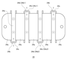
- 3 is a front view of the heat sink shown in FIG. 2 as viewed from a direction A.
- 3 is a top view of the heat sink shown in FIG. 2 as viewed from direction B.
- 1 is a top view of a metal plate before being bent into a heat sink according to an embodiment of the present invention;
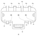
- FIG. 2 is a front view of the light-emitting module according to the present embodiment.
- FIG. 1 is a perspective view of a light-emitting module according to an embodiment of the present invention
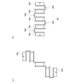
- 8(a) to 8(c) are schematic diagrams for explaining a method for manufacturing a heat sink according to this embodiment.
- 9A and 9B are schematic diagrams for explaining a method for manufacturing a heat sink according to this embodiment.
- Fig. 1 is a vertical cross-sectional view showing an example of a vehicle lamp in which a lighting control module according to the present embodiment can be mounted.
- a headlamp 10 as a vehicle lamp shown in Fig. 1 shows one of left and right headlamps. These headlamps 10 are attached to both sides in the vehicle width direction at the front of the vehicle, and these headlamps 10 illuminate the area ahead of the vehicle.
- the exterior of the headlamp 10 is formed by a lamp body 12 that is open at the front and a front cover 14 that serves as a surface cover that covers the opening of the lamp body 12.
- the lamp body 12 is composed of a rear wall portion 12a that stands upright in the vertical direction, and a peripheral wall portion 12b that projects forward (to the left in FIG. 1) from the peripheral edge of the rear wall portion 12a.
- the rear wall portion 12a extends horizontally (perpendicular to the paper surface in FIG. 1) while maintaining a constant height, and the peripheral wall portion 12b cooperates with the rear wall portion 12a to define the storage space 16, and the tip of the peripheral wall portion 12b forms a horizontally elongated opening 18 in the storage space 16.
- the front cover 14 is removably attached to the tip of the peripheral wall portion 12b of the lamp body 12. As a result, the front cover 14 and the lamp body 12 form a lamp housing, and form a sealed lamp chamber 20 inside.
- the front cover 14 is translucent, and light emitted in the lamp chamber 20 is irradiated to the outside through the front cover 14.
- a resin lens is used for the front cover 14.
- An LED unit 22 is disposed inside the lamp chamber 20. As shown in FIG. 1, the LED unit 22 is provided with a metal heat sink 24 as a conductive base.
- the heat sink 24 in this embodiment integrally includes a plate-shaped metal support plate portion 26 that is attached to the LED unit 22 and a heat dissipation fin portion 28.
- the metal support plate portion 26 and the heat dissipation fin portion 28 may be formed as a single part.
- the metal support plate 26 is supported on the rear wall 12a of the lamp body 12 via aiming screws 30 and the like, and the plate surface of the metal support plate 26 faces the front-rear direction and is positioned spaced forward from the rear wall 12a.
- the heat dissipation fins 28 are attached to the rear surface of the metal support plate 26, and the heat dissipation fins 28 are cooled by a heat dissipation fan 32 attached to the heat sink 24.
- the LED unit 22 comprises a cylindrical lens holder 34 and a projection lens 36 attached to the lens holder 34.
- the rear end of the lens holder 34 is attached to the front of the metal support plate portion 26, and its front end extends forward.
- the projection lens 36 is attached to the front end of the lens holder 34, so that the projection lens 36 is positioned on the optical axis L that extends in the fore-and-aft direction of the vehicle.
- a front cover 14 is disposed in front of the projection lens 36.
- An extension reflector 38 is disposed around the projection lens 36 and the lens holder 34.
- the LED unit 22 includes a light-emitting module 40.
- the light-emitting module 40 includes a resin circuit board 42, a number of light-emitting diodes (LEDs) 44, and a power supply connector 46.
- the circuit board 42 is positioned within the lens holder 34, aligned with the front surface of the metal support plate portion 26, with the board surface 42a of the circuit board 42 facing forward.
- the circuit board 42 is positioned toward the lower side within the lens holder 34, and a power supply circuit (not shown) is formed on the board surface 42a.
- the LEDs 44 are attached to the upper portion of the board surface 42a of the circuit board 42.
- the LEDs 44 are arranged side by side in the vehicle width direction as a surface light source that emits light, with the light-emitting surface facing forward of the vehicle.
- each LED 44 is configured to emit white light by providing a fluorescent layer on the LED chip.
- the power supply connector 46 is attached to the lower portion of the board surface 42a.
- a power source (not shown) is connected to the power supply connector 46 via an LED driver module (LDM) 50 using a wire harness 48, and each LED 44 is connected via a power supply circuit (not shown) on the board surface 42a.
- the LED driver module 50 is disposed in the lower portion of the lamp body 12, and includes a metal case 52 as a conductive case, and a lighting control circuit board 54 housed in the metal case 52.
- the power supply connector 46 and the power source (not shown) are connected via the lighting control circuit board 54 in the metal case 52, and the lighting control circuit board 54 controls the turning on and off of the multiple LEDs 44.
- FIG. 2 is a perspective view of the heat sink according to the present embodiment.
- Fig. 3 is a front view of the heat sink shown in Fig. 2 as viewed from direction A.
- Fig. 4 is a top view of the heat sink shown in Fig. 2 as viewed from direction B.
- Fig. 5 is a top view of a metal plate before bending into the heat sink according to the present embodiment.
- a rectangular metal plate 56 is prepared with predetermined areas (slits 56a, corners 56b, and round holes 56c) punched out so that it can be folded multiple times.
- the material of the metal plate 56 is, for example, aluminum.
- the thickness of the metal plate 56 is, for example, about 1 to 3 mm, and may be in the range of 1.5 to 2.5 mm taking into account strength and workability.
- the heat sink 24 shown in Figures 2 to 4 is constructed by bending a single metal plate 56.
- the heat sink 24 has multiple bent surfaces 24a on which a substrate is placed, and U-shaped fins 24b provided to connect adjacent bent surfaces 24a.
- the bent surfaces 24a may be folded on both sides, such as the three central surfaces of the five surfaces, or may be surfaces at both ends of the five surfaces that are folded on only one side.
- the five bent surfaces 24a form part of the same plane, allowing a substrate to be placed stably, and realizing a heat sink 24 in which U-shaped fins 24b are provided integrally with the bent surfaces 24a.
- the U-shaped fins 24b have ventilation holes 24d on the bottom surface 24c of the U. This allows air to flow in and out not only through the gaps 24e between the fins 24b but also through the bottom surface 24c, improving the heat dissipation effect.
- the bottom surface 24c is provided so that the perpendicular line X1 of the bottom surface 24c and the perpendicular line X2 of the folded surface 24a are in a twisted positional relationship. This makes it easier for air to flow in a direction that intersects with the perpendicular line of the substrate placed on the folded surface 24a (the direction of the perpendicular line X1).
- the bent surface 24a may be a rectangular plane, and the U-shaped fin 24b may have a first U-shaped fin 24b1 connected to one side of the rectangle, and a second U-shaped fin 24b2 connected to the other side opposite the one side (see Figure 3).
- the U-shaped bottom surface 24c1 of the first U-shaped fin 24b1 and the U-shaped bottom surface 24c2 of the second U-shaped fin 24b2 are arranged on either side of the diagonal of a commonly connected rectangular plane (folded surface 24a). This makes it possible to realize a heat sink 24 with ventilation holes 24d on both sides of the folded surface 24a on which the substrate is placed.
- the U-shaped fin 24b has two flat surfaces 24f that are bent from a specific side of the rectangular flat surface (bottom surface 24c) toward the back of the page (see FIG. 4).
- the two opposing flat surfaces 24f are connected at the bottom surface 24c to form the fin 24b with a U-shaped cross section.
- at least a portion of the bottom surface 24c that connects the two flat surfaces 24f includes a flat shape, but the portion of the bottom surface 24c may be configured as a curved surface without including a flat surface.
- Fig. 6 is a front view of the light emitting module according to the present embodiment.
- Fig. 7 is a perspective view of the light emitting module according to the present embodiment.
- the light emitting module 40 according to the present embodiment includes a heat sink 24, a circuit board 42 having a back surface 42b placed on a plurality of folded surfaces, and a plurality of light emitting elements mounted on a board surface 42a of the circuit board 42.
- the light emitting elements according to the present embodiment are LEDs 44. As shown in Fig. 6, the LEDs 44 are arranged so as to overlap with the folded surface 24a when the board surface 42a of the circuit board 42 is viewed from the front. As a result, the folded surface 24a of the heat sink 24 is arranged on the back surface side of each of the LEDs 44, so that the heat of the LEDs 44 is easily transferred to the heat sink 24.
- FIG. 8(a) to 8(c) are schematic diagrams for explaining the method for manufacturing the heat sink according to the present embodiment.
- FIG. 9(a) to 9(b) are schematic diagrams for explaining the method for manufacturing the heat sink according to the present embodiment. Note that the ventilation holes 24d are omitted from each drawing.
- U-shaped fins 24b are formed by folding multiple times in directions different from the specified direction.
- the U-shaped fins 24b are arranged to connect adjacent folded surfaces 24a. In this way, by folding a single metal plate 56, a heat sink 24 having multiple U-shaped fins 24b that contribute to heat dissipation can be manufactured.
- the heat sink 24 described above is easier to manufacture and requires less material costs than cast parts such as aluminum die casting.
- a three-dimensional heat sink 24 with a large heat dissipation area can be manufactured from a rectangular aluminum plate, so that a larger number of aluminum plates can be cut out from a large aluminum plate.
Landscapes
- Engineering & Computer Science (AREA)
- General Engineering & Computer Science (AREA)
- Physics & Mathematics (AREA)
- Thermal Sciences (AREA)
- Microelectronics & Electronic Packaging (AREA)
- Arrangement Of Elements, Cooling, Sealing, Or The Like Of Lighting Devices (AREA)
- Cooling Or The Like Of Semiconductors Or Solid State Devices (AREA)
- Cooling Or The Like Of Electrical Apparatus (AREA)
Abstract
曲げ加工を工夫した新たなヒートシンクを提供する。ヒートシンク24は、一枚の金属板を折り曲げ加工することで構成されたヒートシンクであって、基板が載置される複数の折り曲げ面24aと、隣接する折り曲げ面24a同士を接続するように設けられたU字状のフィン24bと、を有する。U字状のフィン24bは、U字の底面24cに通気孔24dが設けられていてもよい。底面24cは、該底面の垂線X1と折り曲げ面24aの垂線X2とがねじれの位置関係となるように設けられていてもよい。
Description
本発明は、ヒートシンクに関する。
従来、光源の熱を放熱するためのヒートシンクの一部又は全部を一枚の金属薄板を曲げ加工して作製したものが知られている。例えば、熱源体が表面に取り付けられる熱源体取付板と、熱源体取付板に連続して形成された波形状の放熱板と、を備えるヒートシンクが考案されている(特許文献1参照)。
しかしながら、前述のヒートシンクは、矩形の熱源体取付板の一辺から、複数のフィン部からなる放熱板が延びており、熱源体取付板に取り付けられた熱源体が発生する熱を、放熱板のフィン部へと拡散させるまでの経路が長い。そのため、必ずしも放熱が効率的に行えるものとは言えない。
本発明はこうした状況に鑑みてなされたものであり、その目的とするところの一つは、曲げ加工を工夫した新たなヒートシンクを提供することにある。
上記課題を解決するために、本発明のある態様のヒートシンクは、一枚の金属板を折り曲げ加工することで構成されたヒートシンクであって、基板が載置される複数の折り曲げ面と、隣接する折り曲げ面同士を接続するように設けられたU字状のフィンと、を有する。
この態様によると、基板を載置できるとともに折り曲げ面と一体的にU字状のフィンが設けられたヒートシンクを実現できる。
U字状のフィンは、U字の底面に通気孔が設けられていてもよい。これにより、フィンの間だけでなく底面からも空気が流出入するため、放熱効果を向上できる。
底面は、該底面の垂線と折り曲げ面の垂線とがねじれの位置関係となるように設けられていてもよい。これにより、基板の垂線と交差する方向へ空気が流れやすくなる。
折り曲げ面は、矩形の平面であり、U字状のフィンは、矩形の一辺と連なる第1のU字状のフィンと、一辺と対向する他辺と連なる第2のU字状のフィンと、を有していてもよい。
第1のU字状のフィンのU字の底面と第2のU字状のフィンのU字の底面とは、矩形の平面の対角線を挟んで配置されていてもよい。これにより、基板が載置される折り曲げ面の両側に通気孔が配置されたヒートシンクを実現できる。
本発明の別の態様は、発光モジュールである。この発光モジュールは、複数の折り曲げ面と、隣接する折り曲げ面同士を接続するように設けられたU字状のフィンと、を有し、一枚の金属板を折り曲げ加工することで構成されたヒートシンクと、複数の折り曲げ面に一方の面が載置された基板と、基板の他方の面に搭載された発光素子と、を備える。発光素子は、基板の他方の面を正面から見て折り曲げ面と重なるように配置されている。
この態様によると、発光素子の裏面側にヒートシンクの折り曲げ面が配置されているため、発光素子の熱がヒートシンクに移動しやすくなる。
本発明の更に別の態様は、ヒートシンクの製造方法である。この方法は、複数回の折り曲げ加工ができるように矩形の一部が打ち抜かれた一枚の金属板を準備する工程と、金属板を所定方向に二つ折りすることで複数の折り曲げ面を形成する工程と、所定方向と異なる方向に複数回折り曲げることで複数のU字状のフィンを形成する工程と、を含む。U字状のフィンは、隣接する折り曲げ面同士を接続するように設けられている。
この態様によると、一枚の金属板を折り曲げることで放熱性に寄与する複数のU字状のフィンを有するヒートシンクを製造できる。
以上の構成要素の任意の組合せ、本発明の表現を製造方法、灯具や照明などの装置、発光モジュール、光源などの間で変換したものもまた、本発明の態様として有効である。
本発明によれば、曲げ加工を工夫した新たなヒートシンクを提供できる。
以下、本発明を好適な実施の形態をもとに図面を参照しながら説明する。各図面に示される同一または同等の構成要素、部材、処理には、同一の符号を付するものとし、適宜重複した説明は省略する。また、実施の形態は、発明を限定するものではなく例示であって、実施の形態に記述されるすべての特徴やその組合せは、必ずしも発明の本質的なものであるとは限らない。
(車両用灯具)
図1は、本実施の形態に係る点灯制御モジュールを搭載可能な車両用灯具の一例を示す縦断面図である。図1に示す車両用灯具としての前照灯10は、左右前照灯の一方を示す。これら前照灯10は、車両前部における車幅方向両側に取り付けられており、これら前照灯10により車両前方が照射される。
図1は、本実施の形態に係る点灯制御モジュールを搭載可能な車両用灯具の一例を示す縦断面図である。図1に示す車両用灯具としての前照灯10は、左右前照灯の一方を示す。これら前照灯10は、車両前部における車幅方向両側に取り付けられており、これら前照灯10により車両前方が照射される。
前照灯10は、図1に示すように、その外観が、前方が開口されたランプボディ12と、そのランプボディ12の開口を覆う表面カバーとしての前面カバー14とにより形成されている。
ランプボディ12は、上下方向に起立する背壁部12aと、その背壁部12aの周縁部から前方(図1中、左方)に張り出す周壁部12bと、により構成されている。背壁部12aは、一定高さを維持しつつ横方向(図1中、紙面直交方向)に延びており、周壁部12bは、背壁部12aと協働して収納空間16を区画し、その周壁部12bの先端部は、収納空間16における横長形状の開口18を形成している。
前面カバー14は、ランプボディ12の周壁部12b先端部に対して着脱可能に取り付けられている。これにより、前面カバー14とランプボディ12とは、灯具筐体を形成するとともに、その内部に密閉状態の灯室20を形成している。前面カバー14は、透光性を有しており、灯室20において発光する光は、前面カバー14を介して外部に照射される。本実施の形態における前面カバー14は、樹脂製レンズが用いられている。
灯室20の内部には、LEDユニット22が配設されている。LEDユニット22は、図1に示すように、導電性ベースとしての金属製のヒートシンク24を備えている。本実施の形態に係るヒートシンク24は、LEDユニット22に取り付けられる板状の金属製支持板部26と放熱フィン部28とを一体的に有している。なお、金属製支持板部26と放熱フィン部28とが一部品であってもよい。
金属製支持板部26は、ランプボディ12の背壁部12aにエイミングスクリュ30等を介して支持されており、その金属製支持板部26の板面は、前後方向を向きつつ、背壁部12aから前方側に離間された状態で配置されている。放熱フィン部28は、金属製支持板部26の後面に取り付けられており、放熱フィン部28は、ヒートシンク24に取り付けられた放熱ファン32により冷却されることになっている。
LEDユニット22は、筒形状のレンズホルダ34と、レンズホルダ34に取り付けられた投影レンズ36と、を備えている。レンズホルダ34は、その後端部が金属製支持板部26の前面に取り付けられ、その前端部は前方に延出している。投影レンズ36は、レンズホルダ34の前端部に取り付けられており、これにより、投影レンズ36は、車両前後方向に延びる光軸L上に配置されている。投影レンズ36の前方には前面カバー14が配置されている。また、投影レンズ36及びレンズホルダ34の周囲には、エクステンションリフレクタ38が配置されている。
LEDユニット22は、発光モジュール40を備えている。発光モジュール40は、樹脂製の回路基板42と、複数の発光ダイオード(Light Emitting Diode:以下、LEDという)44と、給電コネクタ46と、を備えている。回路基板42は、レンズホルダ34内において、金属製支持板部26の前面上に合わせた状態で配置されており、回路基板42の基板面42aは、前方に向けられている。回路基板42は、レンズホルダ34内において、下側寄りに配置されており、基板面42aには、給電回路(図示略)が形成されている。
複数のLED44は、回路基板42における基板面42aの上側部分に取り付けられている。この複数のLED44は、光を出射する面状光源として、発光面を車両前方に向けつつ車幅方向に並設された状態で配置されており、本実施の形態においては、各LED44は、白色光を出射するようにすべく、LEDチップ上に蛍光層が設けられた構成とされている。
給電コネクタ46は、基板面42aの下側部分に取り付けられている。給電コネクタ46には、ワイヤハーネス48を用いることにより、電源(図示略)がLEDドライバーモジュール(LDM)50を介して接続されているとともに、基板面42a上の給電回路(図示略)を介して各LED44が接続されている。LEDドライバーモジュール50は、ランプボディ12内の下部に配置され、導電性ケースとしての金属製ケース52と、金属製ケース52内に収納される点灯制御回路基板54と、を備えている。そして、給電コネクタ46と電源(図示略)とは、金属製ケース52内の点灯制御回路基板54を介して接続されており、複数のLED44は、点灯制御回路基板54により点消灯制御される。
(ヒートシンク)
図2は、本実施の形態に係るヒートシンクの斜視図である。図3は、図2に示すヒートシンクをA方向から見た正面図である。図4は、図2に示すヒートシンクをB方向から見た上面図である。図5は、本実施の形態に係るヒートシンクへの折り曲げ加工前の金属板の上面図である。
図2は、本実施の形態に係るヒートシンクの斜視図である。図3は、図2に示すヒートシンクをA方向から見た正面図である。図4は、図2に示すヒートシンクをB方向から見た上面図である。図5は、本実施の形態に係るヒートシンクへの折り曲げ加工前の金属板の上面図である。
ヒートシンク24を製造する場合、図5に示すように、複数回の折り曲げ加工ができるように、所定の領域(スリット56aやコーナー部56b、丸穴56c)が打ち抜かれた矩形の一枚の金属板56を準備する。金属板56の材質は、例えば、アルミニウムである。また、金属板56の厚みは、例えば、1~3mm程度の厚みであり、強度と加工性を考慮して1.5~2.5mmの範囲であってもよい。
折り曲げ加工の方法については後述するが、図2乃至図4に示すヒートシンク24は、一枚の金属板56を折り曲げ加工することで構成されている。ヒートシンク24は、基板が載置される複数の折り曲げ面24aと、隣接する折り曲げ面24a同士を接続するように設けられたU字状のフィン24bと、を有する。なお、折り曲げ面24aは、5つあるうちの中央側3つのように両側を折り曲げた折り返し面でもよく、あるいは、5つあるうちの両端にある片側だけ折り曲げた面であってもよい。5つの折り曲げ面24aは、同一平面の一部を構成しており、基板を安定して載置できるとともに、折り曲げ面24aと一体的にU字状のフィン24bが設けられたヒートシンク24を実現できる。
U字状のフィン24bは、U字の底面24cに通気孔24dが設けられている。これにより、フィン24bの間24eだけでなく底面24cからも空気が流出入するため、放熱効果を向上できる。
底面24cは、底面24cの垂線X1と折り曲げ面24aの垂線X2とがねじれの位置関係となるように設けられている。これにより、折り曲げ面24aに載置された基板の垂線と交差する方向(垂線X1方向)へ空気が流れやすくなる。
折り曲げ面24aは、矩形の平面であり、U字状のフィン24bは、矩形の一辺と連なる第1のU字状のフィン24b1と、一辺と対向する他辺と連なる第2のU字状のフィン24b2と、を有していてもよい(図3参照)。
第1のU字状のフィン24b1のU字の底面24c1と第2のU字状のフィン24b2のU字の底面24c2とは、共通して連なる矩形の平面(折り曲げ面24a)の対角線を挟んで配置されている。これにより、基板が載置される折り曲げ面24aの両側に通気孔24dが配置されたヒートシンク24を実現できる。
U字状のフィン24bは、矩形の平面(底面24c)の特定の辺から紙面奥側(図4参照)に屈曲した2つの平面24fを有する。換言すると、対向する2つの平面24fが底面24cでつながることで、断面がU字状のフィン24bが構成される。本実施の形態では、2つの平面24fをつなぐ底面24cの少なくとも一部に平面形状が含まれているが、底面24cの部分が平面を含まずに曲面で構成されていてもよい。
(発光モジュール)
図6は、本実施の形態に係る発光モジュールの正面図である。図7は、本実施の形態に係る発光モジュールの斜視図である。本実施の形態に係る発光モジュール40は、ヒートシンク24と、複数の折り曲げ面に裏面42bが載置された回路基板42と、回路基板42の基板面42aに搭載された複数の発光素子と、を備える。本実施の形態に係る発光素子は、LED44である。LED44は、図6に示すように、回路基板42の基板面42aを正面から見て折り曲げ面24aと重なるように配置されている。これにより、いずれのLED44も、裏面側にヒートシンク24の折り曲げ面24aが配置されているため、LED44の熱がヒートシンク24に移動しやすくなる。
図6は、本実施の形態に係る発光モジュールの正面図である。図7は、本実施の形態に係る発光モジュールの斜視図である。本実施の形態に係る発光モジュール40は、ヒートシンク24と、複数の折り曲げ面に裏面42bが載置された回路基板42と、回路基板42の基板面42aに搭載された複数の発光素子と、を備える。本実施の形態に係る発光素子は、LED44である。LED44は、図6に示すように、回路基板42の基板面42aを正面から見て折り曲げ面24aと重なるように配置されている。これにより、いずれのLED44も、裏面側にヒートシンク24の折り曲げ面24aが配置されているため、LED44の熱がヒートシンク24に移動しやすくなる。
(ヒートシンクの製造方法)
図8(a)~図8(c)は、本実施の形態に係るヒートシンクの製造方法を説明するための模式図である。図9(a)~図9(b)は、本実施の形態に係るヒートシンクの製造方法を説明するための模式図である。なお、各図では通気孔24dの図示を省略している。
図8(a)~図8(c)は、本実施の形態に係るヒートシンクの製造方法を説明するための模式図である。図9(a)~図9(b)は、本実施の形態に係るヒートシンクの製造方法を説明するための模式図である。なお、各図では通気孔24dの図示を省略している。
前述のように図5に示す金属板56を準備し、図8(a)に示すように、複数の折り曲げ面24aとなる部分を挟んで両側の部分を90度折り曲げて二つ折りにする。次に、図8(b)に示すように、両端部の折り曲げ面24aを90度外側に折り曲げる。次に、図8(c)に示すように、2番目と4番目の折り曲げ面24aを90度外側に折り曲げる。さらに、図9(a)に示すように、両端部の折り曲げ面24aを90度内側に折り曲げる。最後に、図9(b)に示すように、2番目と4番目の折り曲げ面24aを90度内側に折り曲げる。
このように、所定方向と異なる方向に複数回折り曲げることで複数のU字状のフィン24bが形成される。U字状のフィン24bは、隣接する折り曲げ面24a同士を接続するように設けられている。これにより、一枚の金属板56を折り曲げることで放熱性に寄与する複数のU字状のフィン24bを有するヒートシンク24を製造できる。
上述のヒートシンク24は、アルミダイキャストのような鋳造部品と比較して、製造が簡単であり材料費も低減できる。また、打ち抜き部分や折り曲げ方を工夫することで、矩形のアルミプレートから立体的で放熱面積の大きなヒートシンク24を製造できるので、大面積のアルミニウム板から複数のアルミプレートを切り出す際の取り数を多くできる。
以上、本発明を上述の実施の形態を参照して説明したが、本発明は上述の実施の形態に限定されるものではなく、実施の形態の構成を適宜組み合わせたものや置換したものについても本発明に含まれるものである。また、当業者の知識に基づいて実施の形態における組合せや処理の順番を適宜組み替えることや各種の設計変更等の変形を実施の形態に対して加えることも可能であり、そのような変形が加えられた実施の形態も本発明の範囲に含まれうる。
本国際出願は、2023年7月18日に出願された日本国特許出願である特願2023-117066号に基づく優先権を主張するものであり、当該日本国特許出願である特願2023-117066号の全内容は、本国際出願に援用される。
本発明の特定の実施の形態についての上記説明は、例示を目的として提示したものである。それらは、網羅的であったり、記載した形態そのままに本発明を制限したりすることを意図したものではない。数多くの変形や変更が、上記の記載内容に照らして可能であることは当業者に自明である。
10 前照灯、 22 LEDユニット、 24 ヒートシンク、 24a 折り曲げ面、 24b フィン、 24c 底面、 24d 通気孔、 40 発光モジュール、 42 回路基板、 42a 基板面、 42b 裏面、 44 LED、 46 給電コネクタ、 56 金属板、 56a スリット。
Claims (7)
- 一枚の金属板を折り曲げ加工することで構成されたヒートシンクであって、
基板が載置される複数の折り曲げ面と、
隣接する前記折り曲げ面同士を接続するように設けられたU字状のフィンと、を有することを特徴とするヒートシンク。 - 前記U字状のフィンは、U字の底面に通気孔が設けられていることを特徴とする請求項1に記載のヒートシンク。
- 前記底面は、該底面の垂線と前記折り曲げ面の垂線とがねじれの位置関係となるように設けられていることを特徴とする請求項2に記載のヒートシンク。
- 前記折り曲げ面は、矩形の平面であり、
前記U字状のフィンは、前記矩形の一辺と連なる第1のU字状のフィンと、前記一辺と対向する他辺と連なる第2のU字状のフィンと、を有することを特徴とする請求項1乃至3のいずれか1項に記載のヒートシンク。 - 前記第1のU字状のフィンのU字の底面と前記第2のU字状のフィンのU字の底面とは、前記矩形の平面の対角線を挟んで配置されていることを特徴とする請求項4に記載のヒートシンク。
- 複数の折り曲げ面と、隣接する前記折り曲げ面同士を接続するように設けられたU字状のフィンと、を有し、一枚の金属板を折り曲げ加工することで構成されたヒートシンクと、
前記複数の折り曲げ面に一方の面が載置された基板と、
前記基板の他方の面に搭載された発光素子と、を備え、
前記発光素子は、前記基板の他方の面を正面から見て前記折り曲げ面と重なるように配置されていることを特徴とする発光モジュール。 - 複数回の折り曲げ加工ができるように矩形の一部が打ち抜かれた一枚の金属板を準備する工程と、
前記金属板を所定方向に二つ折りすることで複数の折り曲げ面を形成する工程と、
前記所定方向と異なる方向に複数回折り曲げることで複数のU字状のフィンを形成する工程と、を含み、
前記U字状のフィンは、隣接する前記折り曲げ面同士を接続するように設けられていることを特徴とするヒートシンクの製造方法。
Applications Claiming Priority (2)
| Application Number | Priority Date | Filing Date | Title |
|---|---|---|---|
| JP2023-117066 | 2023-07-18 | ||
| JP2023117066A JP2025014481A (ja) | 2023-07-18 | 2023-07-18 | ヒートシンク、発光モジュール及びヒートシンクの製造方法 |
Publications (1)
| Publication Number | Publication Date |
|---|---|
| WO2025018201A1 true WO2025018201A1 (ja) | 2025-01-23 |
Family
ID=94281888
Family Applications (1)
| Application Number | Title | Priority Date | Filing Date |
|---|---|---|---|
| PCT/JP2024/024572 Pending WO2025018201A1 (ja) | 2023-07-18 | 2024-07-08 | ヒートシンク、発光モジュール及びヒートシンクの製造方法 |
Country Status (2)
| Country | Link |
|---|---|
| JP (1) | JP2025014481A (ja) |
| WO (1) | WO2025018201A1 (ja) |
Citations (6)
| Publication number | Priority date | Publication date | Assignee | Title |
|---|---|---|---|---|
| JP2004273479A (ja) * | 2003-03-05 | 2004-09-30 | Hitachi Ltd | 放熱フィン付パワー半導体モジュール |
| US20090046433A1 (en) * | 2007-08-17 | 2009-02-19 | Fu Zhun Precision Industry (Shen Zhen) Co., Ltd. | Heat sink for led lamp |
| JP2010146817A (ja) * | 2008-12-17 | 2010-07-01 | Koito Mfg Co Ltd | 車両用灯具 |
| JP3175854U (ja) * | 2012-01-20 | 2012-06-07 | 光碁科技股▲ふん▼有限公司 | 放熱体構造 |
| JP2013004544A (ja) * | 2011-06-10 | 2013-01-07 | Matsuura Kk | ヒートシンク |
| JP2016174034A (ja) * | 2015-03-16 | 2016-09-29 | 株式会社Ihi | 半導体パワーモジュール |
-
2023
- 2023-07-18 JP JP2023117066A patent/JP2025014481A/ja active Pending
-
2024
- 2024-07-08 WO PCT/JP2024/024572 patent/WO2025018201A1/ja active Pending
Patent Citations (6)
| Publication number | Priority date | Publication date | Assignee | Title |
|---|---|---|---|---|
| JP2004273479A (ja) * | 2003-03-05 | 2004-09-30 | Hitachi Ltd | 放熱フィン付パワー半導体モジュール |
| US20090046433A1 (en) * | 2007-08-17 | 2009-02-19 | Fu Zhun Precision Industry (Shen Zhen) Co., Ltd. | Heat sink for led lamp |
| JP2010146817A (ja) * | 2008-12-17 | 2010-07-01 | Koito Mfg Co Ltd | 車両用灯具 |
| JP2013004544A (ja) * | 2011-06-10 | 2013-01-07 | Matsuura Kk | ヒートシンク |
| JP3175854U (ja) * | 2012-01-20 | 2012-06-07 | 光碁科技股▲ふん▼有限公司 | 放熱体構造 |
| JP2016174034A (ja) * | 2015-03-16 | 2016-09-29 | 株式会社Ihi | 半導体パワーモジュール |
Also Published As
| Publication number | Publication date |
|---|---|
| JP2025014481A (ja) | 2025-01-30 |
Similar Documents
| Publication | Publication Date | Title |
|---|---|---|
| US10352526B2 (en) | Cooling member for lighting and/or signaling system | |
| JP2010238604A (ja) | 発光素子モジュール化部材および灯具ユニット | |
| JP2010146817A (ja) | 車両用灯具 | |
| JP7187537B2 (ja) | 光源ユニット、及びこれに用いられる搭載部材の製造方法 | |
| JP5415019B2 (ja) | Led光源装置 | |
| WO2013176080A1 (ja) | 照明装置 | |
| JP6114985B2 (ja) | 車両用前照灯 | |
| JP5503063B1 (ja) | Led照明装置 | |
| US10634309B2 (en) | Motor vehicle lighting module with cooling member | |
| JP4595781B2 (ja) | 車両用灯具 | |
| EP4194743A1 (en) | A lighting device of an automotive vehicle | |
| WO2025018201A1 (ja) | ヒートシンク、発光モジュール及びヒートシンクの製造方法 | |
| JP2017212100A (ja) | 車両用灯具 | |
| JP7655811B2 (ja) | 点灯制御モジュール | |
| EP2413024A2 (en) | Illumination device | |
| WO2018038048A1 (ja) | 車両用灯具 | |
| JP2022175633A (ja) | 灯具ユニット | |
| JP3209315U (ja) | 照明機器 | |
| JP5406540B2 (ja) | 光源モジュール、車輌用灯具及び光源モジュールの製造方法 | |
| CN111692564A (zh) | 灯具单元及车辆用灯具 | |
| WO2015170552A1 (ja) | 車両用灯具 | |
| JP5062429B2 (ja) | 照明装置 | |
| CN220038256U (zh) | 前照灯和车辆 | |
| KR101745991B1 (ko) | 수송기기용 광원장치 | |
| JP2021125311A (ja) | 灯具用カバー、灯具および照明装置 |
Legal Events
| Date | Code | Title | Description |
|---|---|---|---|
| 121 | Ep: the epo has been informed by wipo that ep was designated in this application |
Ref document number: 24842993 Country of ref document: EP Kind code of ref document: A1 |
|
| NENP | Non-entry into the national phase |
Ref country code: DE |