WO2025004740A1 - 液晶組成物、光吸収異方性膜、積層体、画像表示装置及び重合体 - Google Patents
液晶組成物、光吸収異方性膜、積層体、画像表示装置及び重合体 Download PDFInfo
- Publication number
- WO2025004740A1 WO2025004740A1 PCT/JP2024/020692 JP2024020692W WO2025004740A1 WO 2025004740 A1 WO2025004740 A1 WO 2025004740A1 JP 2024020692 W JP2024020692 W JP 2024020692W WO 2025004740 A1 WO2025004740 A1 WO 2025004740A1
- Authority
- WO
- WIPO (PCT)
- Prior art keywords
- group
- liquid crystal
- formula
- substituent
- hydrogen atom
- Prior art date
- Legal status (The legal status is an assumption and is not a legal conclusion. Google has not performed a legal analysis and makes no representation as to the accuracy of the status listed.)
- Ceased
Links
Images
Classifications
-
- B—PERFORMING OPERATIONS; TRANSPORTING
- B32—LAYERED PRODUCTS
- B32B—LAYERED PRODUCTS, i.e. PRODUCTS BUILT-UP OF STRATA OF FLAT OR NON-FLAT, e.g. CELLULAR OR HONEYCOMB, FORM
- B32B7/00—Layered products characterised by the relation between layers; Layered products characterised by the relative orientation of features between layers, or by the relative values of a measurable parameter between layers, i.e. products comprising layers having different physical, chemical or physicochemical properties; Layered products characterised by the interconnection of layers
- B32B7/02—Physical, chemical or physicochemical properties
- B32B7/023—Optical properties
-
- C—CHEMISTRY; METALLURGY
- C08—ORGANIC MACROMOLECULAR COMPOUNDS; THEIR PREPARATION OR CHEMICAL WORKING-UP; COMPOSITIONS BASED THEREON
- C08F—MACROMOLECULAR COMPOUNDS OBTAINED BY REACTIONS ONLY INVOLVING CARBON-TO-CARBON UNSATURATED BONDS
- C08F20/00—Homopolymers and copolymers of compounds having one or more unsaturated aliphatic radicals, each having only one carbon-to-carbon double bond, and only one being terminated by only one carboxyl radical or a salt, anhydride, ester, amide, imide or nitrile thereof
- C08F20/02—Monocarboxylic acids having less than ten carbon atoms, Derivatives thereof
- C08F20/10—Esters
-
- C—CHEMISTRY; METALLURGY
- C08—ORGANIC MACROMOLECULAR COMPOUNDS; THEIR PREPARATION OR CHEMICAL WORKING-UP; COMPOSITIONS BASED THEREON
- C08F—MACROMOLECULAR COMPOUNDS OBTAINED BY REACTIONS ONLY INVOLVING CARBON-TO-CARBON UNSATURATED BONDS
- C08F20/00—Homopolymers and copolymers of compounds having one or more unsaturated aliphatic radicals, each having only one carbon-to-carbon double bond, and only one being terminated by only one carboxyl radical or a salt, anhydride, ester, amide, imide or nitrile thereof
- C08F20/02—Monocarboxylic acids having less than ten carbon atoms, Derivatives thereof
- C08F20/52—Amides or imides
- C08F20/54—Amides, e.g. N,N-dimethylacrylamide or N-isopropylacrylamide
-
- C—CHEMISTRY; METALLURGY
- C08—ORGANIC MACROMOLECULAR COMPOUNDS; THEIR PREPARATION OR CHEMICAL WORKING-UP; COMPOSITIONS BASED THEREON
- C08L—COMPOSITIONS OF MACROMOLECULAR COMPOUNDS
- C08L33/00—Compositions of homopolymers or copolymers of compounds having one or more unsaturated aliphatic radicals, each having only one carbon-to-carbon double bond, and only one being terminated by only one carboxyl radical, or of salts, anhydrides, esters, amides, imides or nitriles thereof; Compositions of derivatives of such polymers
- C08L33/04—Homopolymers or copolymers of esters
- C08L33/14—Homopolymers or copolymers of esters of esters containing halogen, nitrogen, sulfur, or oxygen atoms in addition to the carboxy oxygen
-
- G—PHYSICS
- G02—OPTICS
- G02B—OPTICAL ELEMENTS, SYSTEMS OR APPARATUS
- G02B5/00—Optical elements other than lenses
- G02B5/30—Polarising elements
-
- H—ELECTRICITY
- H10—SEMICONDUCTOR DEVICES; ELECTRIC SOLID-STATE DEVICES NOT OTHERWISE PROVIDED FOR
- H10K—ORGANIC ELECTRIC SOLID-STATE DEVICES
- H10K50/00—Organic light-emitting devices
- H10K50/80—Constructional details
- H10K50/86—Arrangements for improving contrast, e.g. preventing reflection of ambient light
-
- H—ELECTRICITY
- H10—SEMICONDUCTOR DEVICES; ELECTRIC SOLID-STATE DEVICES NOT OTHERWISE PROVIDED FOR
- H10K—ORGANIC ELECTRIC SOLID-STATE DEVICES
- H10K59/00—Integrated devices, or assemblies of multiple devices, comprising at least one organic light-emitting element covered by group H10K50/00
- H10K59/10—OLED displays
Definitions
- the present invention relates to a liquid crystal composition, a light absorbing anisotropic film, a laminate, an image display device, and a polymer.
- Optical films such as optical compensation sheets and retardation films are used in a variety of display devices to eliminate image coloration and control viewing angles.
- Patent Document 1 describes a composition for forming a retardation layer contained in a retardation film as "a cured product of a retardation layer-forming composition that contains a liquid crystal compound, a surfactant, and a solvent, and the surfactant is a polyether-modified silicone having a repeating unit represented by the following general formula (I)" (Claim 1 of Patent Document 1).
- a light-absorption anisotropic film containing a liquid crystal compound and a dichroic substance As an optical film used in a display device, a light-absorption anisotropic film containing a liquid crystal compound and a dichroic substance is known.
- the present inventors have investigated a liquid crystal composition containing a polyether-modified silicone, a liquid crystal compound, and a dichroic substance as described in Patent Document 1, and have found that repelling occurs during the formation of an optically absorptive anisotropic film, and that orientation defects occur in the optically absorptive anisotropic film that is formed.
- the present invention aims to provide a liquid crystal composition, an optically absorptive anisotropic film, a laminate, an image display device, and a polymer that can form an optically absorptive anisotropic film in which repelling is suppressed during formation of the film and the occurrence of alignment defects is suppressed.
- a liquid crystal composition comprising a liquid crystal compound, a dichroic substance, and a polymer having a repeating unit A including a structure represented by formula (A) described below.
- R A1 and R A2 each independently represent a hydrogen atom or an alkyl group.
- R A3 represents a hydrogen atom, a halogen atom, or a substituent.
- X represents a substituent containing one or more structures represented by formula (a) described below.
- * indicates the bond position.
- R a1 , R a2 and R a3 each independently represent an alkyl group, an alkenyl group, an aryl group or an alkylenearyl group, each of which may have a substituent.
- R B4 and R B5 each independently represent a hydrogen atom or an organic group having 1 to 15 carbon atoms.
- R D1 , R D2 and R D3 each independently represent a hydrogen atom, a halogen atom, a cyano group, an alkyl group, an alkenyl group, or an aryl group.
- L D1 represents a single bond, —COO— or —CO—.
- SpD1 represents a divalent hydrocarbon group having 1 to 20 carbon atoms, provided that, among the -CH2- groups constituting a part of the hydrocarbon group, one or two or more non-adjacent -CH2- groups may each independently be substituted with -O-, -S-, -NH- or -N(Q)-, and Q represents a substituent.
- L D2 and L D3 each independently represent a single bond or a divalent linking group.
- CyD represents a divalent linking group containing a mesogenic group.
- D represents a hydrogen-bonding group composed of a hydrogen atom and a nonmetallic atom of Groups 14 to 16. However, the nonmetallic atom may have a substituent.
- n represents an integer of 1 to 3.
- L D2 When n is 2 or 3, a plurality of L D2 may be the same or different, and a plurality of Cy D may be the same or different.
- L D3 represents a single bond, and D represents -COOH, -NHCOR 2 or -CONHR 3.
- R2 and R3 each independently represent an alkyl group or an alkenyl group having 1 to 10 carbon atoms, provided that, among the -CH2- groups constituting a part of the alkyl group and the alkenyl group, one or two or more non-adjacent -CH2- groups may be substituted with -O-.
- the aryl group in R B1 , R B2 and R B3 includes an aryl group having 6 to 30 carbon atoms (preferably 6 to 20 carbon atoms, more preferably 6 to 12 carbon atoms), specifically, a phenyl group, a 2,6-diethylphenyl group, a 3,5-ditrifluoromethylphenyl group, a styryl group, a naphthyl group, and a biphenyl group.
- R B1 , R B2 and R B3 are preferably a hydrogen atom or an alkyl group, more preferably a hydrogen atom or a methyl group, and further preferably a hydrogen atom.
- R B4 and R B5 each independently represent a hydrogen atom or a substituent. When R B4 and R B5 are substituents, R B4 and R B5 may be linked to form a ring.
- the sum of the molecular weight of R B4 and the molecular weight of R B5 is preferably 200 or less, more preferably 100 or less, and even more preferably 70 or less.
- the details of the reason for this are not clear, but it is roughly presumed as follows. That is, if the sum of the molecular weights is 100 or less, there is no steric hindrance of the substituents, and the specific copolymer does not inhibit the alignment of the liquid crystal compound and the dichroic material, and as a result, the degree of order of the liquid crystal is increased, and the degree of alignment of the light absorption anisotropic film is superior.
- the lower limit of the total molecular weight of R B4 and R B5 is preferably 2 or more.
- the substituents represented by R and R are preferably organic groups, more preferably organic groups having 1 to 15 carbon atoms, even more preferably organic groups having 1 to 12 carbon atoms, and particularly preferably organic groups having 1 to 8 carbon atoms, in terms of obtaining better effects of the present invention.
- Examples of the organic group include linear, branched or cyclic alkyl groups, aromatic hydrocarbon groups and heterocyclic groups.
- the alkyl group preferably has 1 to 15 carbon atoms, more preferably 1 to 12 carbon atoms, and even more preferably 1 to 8 carbon atoms.
- a hydrogen atom of the alkyl group may be substituted by a halogen atom, a cyano group , an aryl group , a nitro group , -OZH1 , -C(O) ZH1 , -C(O) OZH1 , -OC(O) ZH1 , -OC ( O ) OZH1 , -NZH1ZH2, -NZH1C ( O) ZH2 , -NZH1C(O) OZH2 , -C(O)NZH1ZH2, -OC ( O )NZH1ZH2 , -NZH1C(O) NZH2OZH3, -SZH1 , -C(S) ZH1 , -C(O ) SZH1 or -SC(O ) ZH1 .
- Z H1 , Z H2 and Z H3 each independently represent a hydrogen atom, a halogen atom, an alkyl group having 1 to 10 carbon atoms, a cyano group or a nitro group.
- groups with which the hydrogen atom of the alkyl group may be substituted -OH, -COOH or an aryl group (a phenyl group is preferred) is preferred in terms of better effects of the present invention.
- the hydrogen atoms of the aromatic hydrocarbon group and the hydrogen atoms of the heterocyclic group are selected from the group consisting of halogen atoms, cyano groups, alkyl groups having 1 to 10 carbon atoms, cyano groups, nitro groups, -OZ H1 , -C(O)Z H1 , -C(O)OZ H1 , -OC(O)Z H1 , -OC(O)OZ H1 , -NZ H1 Z H2 , -NZ H1 C(O)Z H2 , -NZ H1 C(O)OZ H2 , -C(O)NZ H1 Z H2 , -OC(O)NZ H1 Z H2 , -NZ H1 C(O)NZ H2 OZ H3 , -SZ H1 , -C(S)Z H1 , -C(O)SZ H1 , -SC(O)Z H1 ,
- Z H1 , Z H2 and Z H3 each independently represent a hydrogen atom, a halogen atom, an alkyl group having 1 to 10 carbon atoms, a cyano group or a nitro group.
- a hydrogen atom atom, a halogen atom, an alkyl group having 1 to 10 carbon atoms, a cyano group or a nitro group.
- -OH and -B(OH) 2 are preferred in terms of achieving better effects of the present invention.
- R B4 and R B5 are preferably each independently a hydrogen atom or an organic group having 1 to 15 carbon atoms. Suitable embodiments of the organic group are as described above. In view of obtaining superior effects of the present invention, it is preferable that at least one of R B4 and R B5 is a substituent, and it is more preferable that at least one of them is an organic group having 1 to 15 carbon atoms.
- the ring formed by combining R B4 and R B5 is a heterocycle containing the nitrogen atom in formula (B), and may further contain a heteroatom such as an oxygen atom, a sulfur atom or a nitrogen atom in the ring.
- the ring formed by R B4 and R B5 being linked together is preferably a 4- to 8-membered ring, more preferably a 5- to 7-membered ring, and even more preferably a 5- or 6-membered ring, in terms of better effects of the present invention.
- the number of carbon atoms constituting the ring formed by combining R B4 and R B5 is preferably 3 to 7, and more preferably 3 to 6, in terms of obtaining better effects of the present invention.
- the ring formed by linking R and R may or may not have aromaticity; however, in terms of better effects of the present invention, it is preferable that the ring does not have aromaticity.
- Specific examples of the ring formed by combining R B4 and R B5 include the following groups.
- repeating unit B is not limited to the following structure.
- the content of the repeating unit B is preferably 2 to 75 mass%, more preferably 3 to 70 mass%, and even more preferably 5 to 65 mass%, based on the total repeating units (100 mass%) contained in the specific polymer.
- the content of the repeating unit B is within the above range, the effect of the present invention is more excellent, and the degree of orientation of the optically absorptive anisotropic film is more excellent.
- the specific polymer may contain one type of repeating unit B alone or two or more types of repeating units B. When two or more types of repeating units B are contained, the content of the repeating units B means the total content of the repeating units B.
- the repeating unit D is a repeating unit represented by the following formula (D).
- the repeating unit D has a predetermined spacer (Sp D1 in formula (B) described later) and a linking group having a predetermined ring structure (Cy D in formula (B) described later), which is believed to improve the viscosity of the liquid crystal composition and further suppress repelling.
- the repeating unit D since the repeating unit D has a specific hydrogen-bonding group (D in formula (B) described later), it forms a polymer through hydrogen bonding and serves as an air-interface layer with high flatness suitable for aligning a liquid crystal compound and a dichroic substance, and it is considered that the degree of orientation of the optically absorptive anisotropic film formed is further improved.
- SpD1 represents a divalent hydrocarbon group having 1 to 20 carbon atoms.
- the divalent hydrocarbon group may be linear or branched.
- Examples of the divalent hydrocarbon group having 1 to 20 carbon atoms in Sp D1 include a divalent aliphatic hydrocarbon group having 1 to 20 carbon atoms, a divalent alicyclic hydrocarbon group having 3 to 20 carbon atoms, a divalent aromatic hydrocarbon group having 6 to 20 carbon atoms, and a divalent aromatic heterocyclic group having 6 to 20 carbon atoms.
- a divalent aliphatic hydrocarbon group having 1 to 20 carbon atoms is preferable.
- the divalent aliphatic hydrocarbon group having 1 to 20 carbon atoms is preferably an alkylene group having 1 to 15 carbon atoms, more preferably an alkylene group having 1 to 8 carbon atoms, and specific examples of suitable groups include a methylene group, an ethylene group, a propylene group, a butylene group, a pentylene group, a hexylene group, a methylhexylene group, and a heptylene group.
- one or two or more non-adjacent -CH 2 - may each be independently substituted with -O-, -S-, -NH- or -N(Q)-, where Q represents a substituent, and examples of the substituent W include the above-mentioned substituent W, and among these, an alkyl group, an alkoxy group or a halogen atom is preferable.
- L D2 and L D3 each independently represent a single bond or a divalent linking group.
- the divalent linking group in L D2 and L D3 include -C(O)O-, -O-, -S-, -C(O)NR L1 -, -SO 2 -, and -NR L1 R L2 -.
- R L1 and R L2 each independently represent a hydrogen atom or an alkyl group having 1 to 6 carbon atoms which may have a substituent.
- the substituent that the alkyl group having 1 to 6 carbon atoms may have include the substituent W described above, and among them, an alkyl group, an alkoxy group, or a halogen atom is preferable.
- CyD represents a divalent linking group containing a mesogenic group.
- the mesogenic group is a group that represents the main skeleton of the liquid crystal molecule that contributes to the formation of liquid crystal.
- the liquid crystal molecule exhibits liquid crystallinity, which is an intermediate state (mesophase) between a crystalline state and an isotropic liquid state.
- the mesogenic group preferably contains 1 to 10 cyclic structures, and more preferably contains 1 to 7.
- Specific examples of the cyclic structures include aromatic hydrocarbon groups, heterocyclic groups, and alicyclic groups.
- the divalent linking group containing a mesogen group in Cy D is preferably a divalent mesogen group.
- the divalent mesogen group include a divalent aromatic hydrocarbon group, a divalent heterocyclic group, and a divalent alicyclic group.
- Specific examples of the divalent aromatic hydrocarbon group include a phenylene group, a naphthylene group, a fluorene-diyl group, an anthracene-diyl group, and a tetracene-diyl group.
- the divalent heterocyclic group may be either aromatic or non-aromatic, but from the viewpoint of further improving the degree of orientation, it is preferably a divalent aromatic heterocyclic group.
- Examples of the atoms other than carbon constituting the divalent aromatic heterocyclic group include a nitrogen atom, a sulfur atom, and an oxygen atom.
- these atoms may be the same or different.
- divalent aromatic heterocyclic groups include, for example, a pyridylene group (pyridine-diyl group), a pyridazine-diyl group, an imidazole-diyl group, a thienylene group (thiophene-diyl group), a quinolylene group (quinoline-diyl group), an isoquinolylene group (isoquinoline-diyl group), an oxazole-diyl group, a thiazole-diyl group, an oxadiazole-diyl group, a benzothiazole-diyl group, a benzothiadiazole-diyl group, a phthalimido-diyl group, a thienothiazole-diyl group, a thiazolothiazole-diyl group, a thienothiophene-diyl group, and a
- divalent alicyclic group examples include a cyclopentylene group and a cyclohexylene group, and the carbon atom may be substituted with -O-, -Si( CH3 ) 2- , -N( ZM )- ( ZM represents a hydrogen atom, an alkyl group having 1 to 4 carbon atoms, a cycloalkyl group, an aryl group, a cyano group, or a halogen atom), -C(O)-, -S-, -C(S)-, -S(O)-, -SO2- , or a group consisting of a combination of two or more of these groups.
- Cy D is a divalent linking group represented by any one of the following formulae (Cy D -1) to (Cy D -15).
- * represents the bonding position with L D2 or L D3
- the carbon atom constituting the ring structure in the following formulae may be substituted with a heteroatom or may have a substituent.
- the substituent that the carbon atom constituting the ring structure may have include the above-mentioned substituent W, and among these, an alkyl group, an alkoxy group, or a halogen atom is preferable.
- divalent linking group represented by any one of the above formulas (Cy D -1) to (Cy D -15) include a 1,4-phenylene group, a 1,4-cyclohexylene group, a 1,4-cyclohexenyl group, a tetrahydropyran-2,5-diyl group, a 1,4-piperazine group, a 1,4-piperidine group, a 1,3-dioxane-2,5-diyl group, a tetrahydrothiopyran-2,5-diyl group, a 1,4-bicyclo(2,2,2)octylene group, a decahydronaphthalene-2,6-diyl group, a pyridine-2,5-diyl group, a pyrimidine-2,5-diyl group, a pyr ...
- alkyl group examples include arylazine-2,5-diyl group, 1,2,3,4-tetrahydronaphthalene-2,6-diyl group, 2,6-naphthylene group, phenanthrene-2,7-diyl group, 9,10-dihydrophenanthrene-2,7-diyl group, 1,2,3,4,4a,9,10a-octahydrophenanthrene-2,7-diyl group, 9-fluorenone-2,7-diyl, fluorene-2,7-diyl group, thienothiophene-3,6-diyl group, carbazole-3,6-diyl group, and carbazole-2,7-diyl group.
- Cy D in the above formula (B) is preferably a divalent linking group represented by any one of the above formulae (Cy D -1), (Cy D -4), (Cy D -7), (Cy D -10) and (Cy D -13), and more preferably a divalent linking group represented by any one of the above formulae (Cy D -7) and (Cy D -13).
- D represents a hydrogen-bonding group composed of a hydrogen atom and a nonmetallic atom of Groups 14 to 16 (periodic table), provided that the nonmetallic atom may have a substituent.
- the non-metallic atoms of Groups 14 to 16 include oxygen atoms, sulfur atoms, nitrogen atoms, and carbon atoms.
- examples of the substituent that a non-metallic atom may have include a halogen atom, an alkyl group, an alkoxy group, an alkyl-substituted alkoxy group, a cyclic alkyl group, an aryl group (e.g., a phenyl group, a naphthyl group, etc.), a cyano group, an amino group, a nitro group, an alkylcarbonyl group, a sulfo group, and a hydroxyl group.
- a halogen atom an alkyl group, an alkoxy group, an alkyl-substituted alkoxy group, a cyclic alkyl group, an aryl group (e.g., a phenyl group, a naphthyl group, etc.), a cyano group, an amino group, a nitro group, an alkylcarbonyl group, a sulfo group, and a hydroxyl
- Such hydrogen bond-forming groups include, for example, hydrogen bond donor groups and hydrogen bond acceptor groups.
- the hydrogen bond donor group include an amino group, an amide group, a urea group, a urethane group, a sulfonylamino group, a sulfo group, a phospho group, a hydroxy group, a mercapto group, a carboxy group, a methylene group substituted with an electron-withdrawing group, and a methine group substituted with an electron-withdrawing group.
- the carboxy group and the amide group are preferable.
- the hydrogen bond accepting group include a heteroatom having an unshared electron pair on a heterocycle, a hydroxy group, an aldehyde, a ketone, a carboxy group, a carboxylic acid ester, a carboxylic acid amide, a lactone, a lactam, a sulfonic acid amide, a sulfo group, a phospho group, a phosphoric acid amide, a urethane, a urea, an ether structure (particularly a polymer structure having an oxygen atom contained in a polyether structure), an aliphatic amine, and an aromatic amine.
- the carboxy group and the amide group are preferable.
- n represents an integer of 1 to 3.
- n 2 or 3
- multiple L D2 may be the same or different
- multiple Cy D may be the same or different.
- n in the above formula (D) is preferably 1 or 2 because the haze of the optically absorptive anisotropic film is less observable (the haze is better), and more preferably 2 because repelling is more suppressed when the optically absorptive anisotropic film is formed.
- the repeating unit D is a repeating unit in which L D3 in the above formula (D) represents a single bond and D represents -COOH, -NHCOR 2 or -CONHR 3 .
- R2 and R3 each independently represent an alkyl group or alkenyl group having 1 to 10 carbon atoms.
- the alkyl group and alkenyl group may be linear or branched.
- one or two or more non-adjacent -CH2- groups may be substituted with -O-.
- the repeating unit D is preferably a repeating unit in which L D3 in the above formula (D) represents a single bond and D represents -NHCOR 4 , because this makes it more difficult to observe haze in the optically absorptive anisotropic film.
- R4 represents an alkyl group or alkenyl group having 1 to 3 carbon atoms.
- the alkyl group and alkenyl group may be linear or branched. However, among the -CH2- groups constituting a part of the alkyl group and alkenyl group, one or two or more non-adjacent -CH2- groups may be substituted with -O-.
- Examples of the monomer that forms the repeating unit D include the monomer represented by the following formula.
- Me represents a methyl group
- Ac represents an acetyl group.
- the content of the repeating unit D is preferably 5 to 85 mass%, more preferably 10 to 75 mass%, and even more preferably 20 to 70 mass%, based on the total repeating units (100 mass%) contained in the specific polymer.
- the content of the repeating unit D is within the above range, the effect of the present invention is more excellent, and the degree of orientation of the optically absorptive anisotropic film is more excellent.
- the specific polymer may contain one type of repeating unit D alone or two or more types of repeating units D. When two or more types of repeating units D are contained, the content of the repeating units D means the total content of the repeating units D.
- the specific polymer may have a repeating unit X represented by the formula X.
- R X1 , R X2 and R X3 each independently represent a hydrogen atom, an alkyl group, an alkenyl group, or an aryl group. Specific examples and preferred embodiments of the alkyl group, alkenyl group and aryl group in R X1 , R X2 and R X3 are the same as the alkyl group, alkenyl group and aryl group in R B1 , R B2 and R B3 in formula (B).
- R X1 , R X2 and R X3 are preferably a hydrogen atom or an alkyl group, more preferably a hydrogen atom or a methyl group, and further preferably a hydrogen atom.
- L X1 represents a single bond or —CO—, and preferably —CO—.
- L X2 represents a divalent aliphatic hydrocarbon group having 1 to 20 carbon atoms.
- the aliphatic hydrocarbon group may be linear or branched.
- an alkylene group having 1 to 15 carbon atoms is preferable, and an alkylene group having 1 to 8 carbon atoms is more preferable.
- Specific suitable examples thereof include a methylene group, an ethylene group, a propylene group, a butylene group, a pentylene group, a hexylene group, a methylhexylene group, and a heptylene group.
- the -CH 2 - constituting a part of the hydrocarbon group in L X2 one or more -CH 2 - may each independently be substituted with -O-, -C(O)O- or a phenylene group.
- L Y1 represents a single bond or —CO—, and —CO— is preferable.
- L Y2 represents a divalent aliphatic hydrocarbon group having 1 to 20 carbon atoms.
- the aliphatic hydrocarbon group may be linear or branched.
- an alkylene group having 1 to 15 carbon atoms is preferable, and an alkylene group having 1 to 8 carbon atoms is more preferable.
- Specific suitable examples thereof include a methylene group, an ethylene group, a propylene group, a butylene group, a pentylene group, a hexylene group, a methylhexylene group, and a heptylene group.
- Q 1 Y represents a crosslinkable group represented by the above formulae (P1) to (P30), and preferred embodiments are the same.
- the content of the repeating unit Y is preferably 3 to 75 mass%, more preferably 5 to 70 mass%, and even more preferably 10 to 60 mass%, based on the total repeating units (100 mass%) contained in the specific polymer.
- the content of the repeating unit X is within the above range, the effect of the present invention is more excellent, and the degree of orientation of the optically absorptive anisotropic film is more excellent.
- the repeating unit Y may be contained in the specific polymer in one type alone or in two or more types. When two or more types of repeating unit Y are contained, the content of the repeating unit Y means the total content of the repeating unit Y.
- the specific polymer may have a repeating unit Z represented by the formula Z.
- R Z1 , R Z2 and R Z3 each independently represent a hydrogen atom, an alkyl group, an alkenyl group or an aryl group.
- Specific examples and preferred embodiments of the alkyl group, alkenyl group and aryl group in R Z1 , R Z2 and R Z3 are the same as the alkyl group, alkenyl group and aryl group in R B1 , R B2 and R B3 in formula (B).
- R Z1 , R Z2 and R Z3 are preferably a hydrogen atom or an alkyl group, more preferably a hydrogen atom or a methyl group, and further preferably a hydrogen atom.
- L Z1 represents a single bond or —CO—, and —CO— is preferable.
- L Z2 represents a single bond or a divalent aliphatic hydrocarbon group having 1 to 20 carbon atoms.
- the aliphatic hydrocarbon group may be linear or branched. However, L Z1 and L Z2 cannot be single bonds at the same time.
- the divalent aliphatic hydrocarbon group having 1 to 20 carbon atoms an alkylene group having 1 to 15 carbon atoms is preferable, and an alkylene group having 1 to 8 carbon atoms is more preferable. Specific suitable examples thereof include a methylene group, an ethylene group, a propylene group, a butylene group, a pentylene group, a hexylene group, a methylhexylene group, and a heptylene group.
- the -CH 2 - constituting a part of the hydrocarbon group in L Z2 one or more -CH 2 - may each independently be substituted with -O-.
- repeating unit Z is not limited to the following structure.
- the content of the repeating unit Z is preferably 0.05 to 60 mass%, more preferably 0.05 to 30 mass%, further preferably 0.05 to 10 mass%, and particularly preferably 0.05 to 5 mass%, based on the total repeating units (100 mass%) contained in the specific polymer.
- the content of the repeating unit Z is within the above range, the effect of the present invention is more excellent, and the degree of orientation of the optically absorptive anisotropic film is more excellent.
- the specific polymer may contain one type of repeating unit Z alone or two or more types of repeating units Z. When two or more types of repeating units Z are contained, the content of the repeating units Z refers to the total content of the repeating units Z.
- the content of the specific polymer is preferably 0.01 to 10% by mass, more preferably 0.02 to 5% by mass, and even more preferably 0.2 to 1.5% by mass, based on the total solid content by mass of the liquid crystal composition.
- the content of the specific polymer is preferably 0.01 to 10 parts by mass, more preferably 0.02 to 5 parts by mass, and even more preferably 0.2 to 1.5 parts by mass, relative to 100 parts by mass of the total amount of the liquid crystal compound and the dichroic substance in the liquid crystal composition.
- the effect of the present invention is more excellent, and the degree of orientation of the light absorption anisotropic film is more excellent.
- the mass ratio of the content of the specific polymer to the content of the dichroic substance is preferably from 0.0007 to 0.6, more preferably from 0.0012 to 0.3, and even more preferably from 0.008 to 0.15.
- the mass ratio is within the above range, the degree of orientation of the optically absorptive anisotropic film is superior, which is presumably due to the improved compatibility between the specific polymer and the dichroic material.
- the weight average molecular weight (Mw) of the specific polymer is preferably from 2,000 to 1,000,000, more preferably from 3,000 to 200,000, and even more preferably from 5,000 to 80,000, in terms of obtaining better effects of the present invention.
- the weight average molecular weight of the specific polymer can be measured by the method described in the Examples section below.
- the liquid crystal composition of the present invention may contain components (hereinafter also referred to as "other components") other than the above-mentioned liquid crystal compound, dichroic substance and specific polymer.
- other components include an interface improver, an alignment agent, a polymerization initiator, and a solvent.
- the liquid crystal composition of the present invention may contain a surfactant.
- a surfactant By containing a surfactant, it is expected that the smoothness of the coating surface is improved, the degree of alignment is further improved, and repelling and unevenness are suppressed, thereby further improving the in-plane uniformity.
- a fluorine (meth)acrylate polymer as described in, for example, paragraphs [0018] to [0043] of JP-A-2007-272185 can be used.
- the surfactant a compound other than these may also be used.
- the surfactant one type may be used alone, or two or more types may be used in combination.
- the content of the surfactant is preferably from 0.01 to 10% by mass, more preferably from 0.02 to 5% by mass, based on the total solid content by mass of the liquid crystal composition.
- the liquid crystal composition of the present invention may contain an alignment agent.
- the alignment agent include a boronic acid compound and an onium salt.
- the boronic acid compound functions as a horizontal alignment agent or a vertical alignment agent.
- the onium salt functions as a vertical alignment agent.
- the alignment agent may be used alone or in combination of two or more kinds.
- boronic acid compound a compound represented by formula (30) is preferred.
- R 1 and R 2 each independently represent a hydrogen atom, a substituted or unsubstituted aliphatic hydrocarbon group, a substituted or unsubstituted aryl group, or a substituted or unsubstituted heterocyclic group.
- R3 represents a substituent containing a (meth)acrylic group.
- Specific examples of the boronic acid compound include the boronic acid compounds represented by general formula (I) described in paragraphs 0023 to 0032 of JP-A-2008-225281. As the boronic acid compound, the compounds exemplified below are also preferred.
- onium salts include the onium salts described in paragraphs 0052 to 0058 of JP-A-2012-208397, the onium salts described in paragraphs 0024 to 0055 of JP-A-2008-026730, and the onium salts described in JP-A-2002-37777.
- the content of the alignment agent is preferably 0.01 to 30 mass %, more preferably 0.1 to 10 mass %, based on the total solid mass of the liquid crystal composition.
- the liquid crystal composition of the present invention may contain a polymerization initiator.
- the polymerization initiator is not particularly limited, but is preferably a compound having photosensitivity, that is, a photopolymerization initiator.
- a photopolymerization initiator various compounds can be used without any particular limitation. Examples of the photopolymerization initiator include ⁇ -carbonyl compounds (see U.S. Pat. Nos. 2,367,661 and 2,367,670), acyloin ethers (see U.S. Pat. No. 2,448,828), ⁇ -hydrocarbon-substituted aromatic acyloin compounds (see U.S. Pat. No.
- a photopolymerization initiator commercially available products can be used, such as Irgacure 184, Irgacure 907, Irgacure 369, Irgacure 651, Irgacure 819, Irgacure OXE-01, and Irgacure OXE-02 manufactured by BASF.
- the polymerization initiator may be used alone or in combination of two or more kinds.
- the content of the polymerization initiator is preferably 0.01 to 30 mass %, more preferably 0.1 to 15 mass %, based on the total solid mass of the liquid crystal composition.
- the liquid crystal composition of the present invention preferably contains a solvent from the viewpoint of workability and the like.
- the solvent include ketones (e.g., acetone, 2-butanone, methyl isobutyl ketone, cyclopentanone, and cyclohexanone), ethers (e.g., dioxane, tetrahydrofuran, tetrahydropyran, dioxolane, tetrahydrofurfuryl alcohol, and cyclopentyl methyl ether), aliphatic hydrocarbons (e.g., hexane), alicyclic hydrocarbons (e.g., cyclohexane), aromatic hydrocarbons (e.g., benzene, toluene, xylene, and trimethylbenzene), halogenated carbons (e.g., dichloromethane, trichloromethane (chloroform), dichloroethane, dichlor
- the solvent examples include organic solvents such as ethyl acetate, ethyl acetate, butyl acetate, diethyl carbonate, etc., esters (e.g., methyl acetate, ethyl acetate, butyl acetate, diethyl carbonate, etc.), alcohols (e.g., ethanol, isopropanol, butanol, and cyclohexanol), cellosolves (e.g., methyl cellosolve, ethyl cellosolve, and 1,2-dimethoxyethane, etc.), cellosolve acetates, sulfoxides (e.g., dimethyl sulfoxide, etc.), amides (e.g., dimethylformamide, dimethylacetamide, N-methylpyrrolidone, N-ethylpyrrolidone, 1,3-dimethyl-2-imidazolidinone, etc.), and heterocyclic compounds
- the content of the solvent is preferably 70 to 99% by mass, more preferably 83 to 97% by mass, and even more preferably 85 to 95% by mass, based on the total mass of the liquid crystal composition.
- the optically absorptive anisotropic film of the present invention is an optically absorptive anisotropic film (optically absorptive anisotropic layer) formed using the above-mentioned liquid crystal composition of the present invention.
- the method for producing the optically absorptive anisotropic film of the present invention is not particularly limited, but because the degree of orientation of the obtained optically absorptive anisotropic film is higher, a method comprising, in this order, a step of applying the above-mentioned liquid crystal composition onto an alignment film to form a coating film (hereinafter also referred to as the "coating film forming step") and a step of orienting the liquid crystal component contained in the coating film (hereinafter also referred to as the "orientation step”) is preferred (hereinafter also referred to as the present manufacturing method).
- the liquid crystal component includes not only the above-mentioned liquid crystal compounds but also dichroic substances having liquid crystal properties. Each step will be described below.
- the coating film forming step is a step of coating the above-mentioned liquid crystal composition on the alignment film to form a coating film.
- a liquid crystal composition containing the above-mentioned solvent or by using a liquid crystal composition that has been made into a liquid such as a molten liquid by heating or the like, it becomes easy to apply the liquid crystal composition onto the alignment film.
- the method for applying the liquid crystal composition include known methods such as roll coating, gravure printing, spin coating, wire bar coating, extrusion coating, direct gravure coating, reverse gravure coating, die coating, spraying, and ink jet methods.
- the alignment film can be provided by such means as rubbing an organic compound (preferably a polymer) on the film surface, oblique deposition of an inorganic compound, formation of a layer having microgrooves, or accumulation of an organic compound (e.g., ⁇ -tricosanoic acid, dioctadecylmethylammonium chloride, methyl stearate, etc.) by the Langmuir-Blodgett method (LB film).
- LB film Langmuir-Blodgett method
- an alignment film formed by a rubbing treatment is preferred from the viewpoint of ease of control of the pretilt angle of the alignment film, and a photo-alignment film formed by irradiation with light is also preferred from the viewpoint of uniformity of alignment.
- the thickness of the alignment film is preferably 0.01 to 10 ⁇ m, and more preferably 0.01 to 1 ⁇ m.
- Preferred examples include aromatic ester compounds described in JP-A-2002-265541 and JP-A-2002-317013, maleimide and/or alkenyl-substituted nadimide compounds having a photo-orientable unit described in Japanese Patent Nos. 4205195 and 4205198, and photo-crosslinkable polyimides, polyamides, or esters described in JP-A-2003-520878, JP-A-2004-529220, or Japanese Patent No. 4162850. More preferred are azo compounds, photo-crosslinkable polyimides, polyamides, or esters.
- Light sources used for light irradiation include commonly used light sources, such as lamps such as tungsten lamps, halogen lamps, xenon lamps, xenon flash lamps, mercury lamps, mercury xenon lamps, and carbon arc lamps, various lasers [e.g., semiconductor lasers, helium-neon lasers, argon ion lasers, helium-cadmium lasers, and YAG (yttrium aluminum garnet) lasers], light-emitting diodes, and cathode ray tubes.
- lamps such as tungsten lamps, halogen lamps, xenon lamps, xenon flash lamps, mercury lamps, mercury xenon lamps, and carbon arc lamps
- various lasers e.g., semiconductor lasers, helium-neon lasers, argon ion lasers, helium-cadmium lasers, and YAG (yttrium aluminum garnet) lasers
- light-emitting diodes e.g.,
- Means for obtaining linearly polarized light include a method using a polarizing plate (e.g., an iodine polarizing plate, a dichroic material polarizing plate, and a wire grid polarizing plate), a method using a prism-based element (e.g., a Glan-Thompson prism) or a reflective polarizer that utilizes the Brewster angle, or a method using light emitted from a polarized laser light source. Also, a filter or a wavelength conversion element may be used to selectively irradiate only light of the required wavelength.
- a polarizing plate e.g., an iodine polarizing plate, a dichroic material polarizing plate, and a wire grid polarizing plate
- a prism-based element e.g., a Glan-Thompson prism
- a reflective polarizer that utilizes the Brewster angle
- a filter or a wavelength conversion element may be used
- the alignment step is a step of aligning the dichroic material contained in the coating film. This results in the optically absorptive anisotropic film of the present invention.
- the orientation step may include a drying treatment. By the drying treatment, components such as a solvent can be removed from the coating film.
- the drying treatment may be performed by leaving the coating film at room temperature for a predetermined time (for example, natural drying), or may be performed by heating and/or blowing air.
- the dichroic substance contained in the liquid crystal composition may be aligned by the above-mentioned coating film forming step or drying treatment.
- the coating film may be dried to remove the solvent from the coating film, whereby the dichroic substance contained in the coating film may be aligned, thereby obtaining the optically absorptive anisotropic film of the present invention.
- the alignment step preferably includes a heat treatment, which allows the dichroic material contained in the coating film to be more oriented, thereby increasing the degree of orientation of the resulting optically absorptive anisotropic film.
- the heat treatment is preferably performed at 10 to 250° C., more preferably at 25 to 190° C.
- the heating time is preferably 1 to 300 seconds, more preferably 1 to 60 seconds.
- the orientation step may include a cooling treatment carried out after the heating treatment.
- the cooling treatment is a treatment for cooling the coated film after heating to about room temperature (20 to 25°C). This further fixes the orientation of the dichroic material contained in the coated film, and the degree of orientation of the obtained optically absorptive anisotropic film is increased.
- the cooling means is not particularly limited and can be carried out by a known method.
- the present production method may include a step of curing the optically absorptive anisotropic film (hereinafter also referred to as a "curing step") after the above-mentioned alignment step.
- the curing step is carried out, for example, by heating and/or light irradiation (exposure), and among these, the curing step is preferably carried out by light irradiation.
- the light source used for curing may be various light sources such as infrared light, visible light, or ultraviolet light, but ultraviolet light is preferred.
- ultraviolet light may be irradiated while heating during curing, or ultraviolet light may be irradiated through a filter that transmits only specific wavelengths.
- the exposure may be carried out under a nitrogen atmosphere.
- the curing of the optically absorptive anisotropic film proceeds by radical polymerization, it is preferable to carry out the exposure under a nitrogen atmosphere, since this reduces the inhibition of polymerization caused by oxygen.
- the liquid crystal compound and the dichroic substance contained in the optically absorptive anisotropic film of the present invention are fixed in their alignment state.
- One embodiment of the optically absorptive anisotropic film of the present invention is an embodiment in which the angle ⁇ between the transmittance central axis of the optically absorptive anisotropic film and the normal direction to the surface of the optically absorptive anisotropic film (hereinafter also abbreviated as "transmittance central axis angle ⁇ ”) is more than 45° and not more than 90°, more preferably 75° or more and 90° or less, and even more preferably 80° or more and 90° or less.
- a laminate having a light absorptive anisotropic film (polarizer) having a transmittance central axis angle ⁇ of more than 45° and not more than 90° and a ⁇ /4 plate (described later) is suitably used as a circular polarizing plate.
- polarizer light absorptive anisotropic film
- optically absorptive anisotropic film of the present invention include an embodiment in which the transmittance central axis angle ⁇ is 0° or more and 45° or less, more preferably 0° or more and 35° or less, and even more preferably 0° or more and less than 35°.
- the central axis of transmittance means the direction that shows the highest transmittance when the transmittance is measured by changing the inclination angle (polar angle) and inclination direction (azimuth angle) relative to the normal direction of the optically absorptive anisotropic film surface.
- the Mueller matrix at a wavelength of 550 nm is measured using AxoScan OPMF-1 (manufactured by Optoscience).
- the azimuth angle at which the transmittance central axis is tilted is first found, and then, within a plane including the normal direction of the optically absorptive anisotropic film along that azimuth angle (a plane including the transmittance central axis and perpendicular to the film surface), the polar angle, which is the angle with respect to the normal direction of the optically absorptive anisotropic film surface, is changed from -70 to 70° in 1° increments, and the Mueller matrix at a wavelength of 550 nm is measured, and the transmittance of the optically absorptive anisotropic film is derived.
- the central axis of transmittance means the direction of the absorption axis (the long axis direction of the molecule) of the dichroic material contained in the optically absorptive anisotropic film.
- the transmittance central axis angle ⁇ can be set to a desired value, for example, by adjusting the type and content of the alignment agent.
- the laminate of the present invention has an optically absorptive anisotropic film, and the optically absorptive anisotropic film may be disposed on a substrate.
- an alignment film may be disposed between the substrate and the optically absorptive anisotropic film.
- the substrate is preferably a transparent support.
- the transparent support means a support having a visible light transmittance of 60% or more, preferably 80% or more, and more preferably 90% or more.
- the transparent support is not particularly limited, and any known transparent resin film, transparent resin plate, transparent resin sheet, etc. may be used.
- transparent resin films examples include cellulose acylate films (e.g., cellulose triacetate film (refractive index 1.48), cellulose diacetate film, cellulose acetate butyrate film, and cellulose acetate propionate film), polyethylene terephthalate films, polyethersulfone films, polyacrylic resin films, polyurethane resin films, polyester films, polycarbonate films, polysulfone films, polyether films, polymethylpentene films, polyether ketone films, and (meth)acrylonitrile films.
- cellulose acylate films e.g., cellulose triacetate film (refractive index 1.48), cellulose diacetate film, cellulose acetate butyrate film, and cellulose acetate propionate film
- polyethylene terephthalate films polyethersulfone films
- polyacrylic resin films polyurethane resin films
- polyester films polycarbonate films
- polysulfone films polyether films
- polymethylpentene films polyether ketone films
- a cellulose acylate film which has high transparency, low optical birefringence, and is easy to produce, and is generally used as a protective film for a polarizing plate, is preferred, and a cellulose triacetate film is more preferred.
- the thickness of the substrate is usually 20 to 100 ⁇ m. In the present invention, it is particularly preferable that the substrate is a cellulose ester film and that the thickness thereof is 20 to 70 ⁇ m.
- optically absorptive anisotropic film of the present invention is as described above, and therefore the description thereof will be omitted.
- the alignment film (alignment layer) is as described above, and therefore the description thereof will be omitted.
- One of the preferred embodiments of the laminate of the present invention includes an optically absorptive anisotropic film (particularly, an optically absorptive anisotropic film having a transmittance central axis angle ⁇ of more than 45° and not more than 90°) and a ⁇ /4 plate.
- Such a laminate optical film is preferably used as a circularly polarizing plate.
- the ⁇ /4 plate is a plate having a ⁇ /4 function, specifically, a plate having a function of converting linearly polarized light of a certain wavelength into circularly polarized light (or circularly polarized light into linearly polarized light).
- specific examples of the ⁇ /4 plate having a single layer structure include a stretched polymer film and a retardation film having a light absorbing anisotropic film having ⁇ /4 function provided on a support
- specific examples of the ⁇ /4 plate having a multilayer structure include a broadband ⁇ /4 plate formed by laminating a ⁇ /4 plate and a ⁇ /2 plate.
- the ⁇ /4 plate and the optically absorptive anisotropic film may be provided in contact with each other, or another layer may be provided between the ⁇ /4 plate and the optically absorptive anisotropic film.
- Such layers include an adhesive layer or a bonding layer for ensuring adhesion, and a barrier layer.
- Another preferred embodiment of the laminate of the present invention includes an optically absorptive anisotropic film (particularly an optically absorptive anisotropic film having a transmittance central axis angle ⁇ of 0° or more and 45° or less) and a polarizer having an in-plane absorption axis.
- Such a laminate optical film
- the polarizer is preferably disposed on the opposite side of the optically absorptive anisotropic film to the substrate.
- the polarizer may be disposed in contact with the surface of the optically absorptive anisotropic film, or may be disposed on the surface of the optically absorptive anisotropic film via another layer (for example, a known adhesive layer or pressure-sensitive adhesive layer).
- the polarizer is not particularly limited as long as it has an absorption axis in the plane and has a function of converting light into a specific linearly polarized light, and a conventionally known polarizer can be used.
- a conventionally known polarizer can be used as the polarizer.
- an iodine-based polarizer, a dye-based polarizer using a dichroic dye, a polyene-based polarizer, etc. are used.
- the iodine-based polarizer and the dye-based polarizer include a coating type polarizer and a stretching type polarizer, and either of them can be used.
- polarizer a polarizer in which a dichroic organic dye is oriented by utilizing the orientation of a liquid crystal compound is preferred, and as a stretched polarizer, a polarizer produced by adsorbing iodine or a dichroic dye to polyvinyl alcohol and stretching it is preferred.
- optically absorptive anisotropic film examples include an optically absorptive anisotropic film containing a dichroic dye compound that is horizontally aligned (in a direction intersecting the thickness direction of the optically absorptive anisotropic film) and does not contain a liquid crystal compound as described in JP 2010-152351 A, and an optically absorptive anisotropic film containing a liquid crystal compound and a horizontally aligned dichroic dye compound as described in WO 2017/154907 A.
- the laminate of the present invention preferably has a barrier layer in addition to the optically absorptive anisotropic film.
- the barrier layer is also called a gas barrier layer (oxygen barrier layer), and has the function of protecting the polarizing element of the present invention from gases such as oxygen in the atmosphere, moisture, or compounds contained in adjacent layers.
- the laminate of the present invention preferably has a barrier layer having an oxygen permeability coefficient of 200 cc/ m2 day atm or less adjacent to the optically absorptive anisotropic film, and more preferably has a barrier layer having an oxygen permeability coefficient of 50 cc/ m2 day atm or less, for the reason of further improving durability.
- the barrier layer does not need to be provided.
- the oxygen permeability coefficient is an index representing the amount of oxygen passing through a membrane per unit time and unit area, and in the present invention, a value measured with an oxygen concentration device (e.g., Model 3600 manufactured byhack Ultra Analytical Co., Ltd.) in an environment of 25°C and 50% relative humidity (RH) is used.
- the organic compounds contained in the barrier layer include polymerizable compounds with high hydrogen bonding properties and compounds with many polymerizable groups per molecular weight, due to their high oxygen blocking function.
- Examples of compounds with many polymerizable groups per molecular weight include pentaerythritol tetra(meth)acrylate and dipentaerythritol hexa(meth)acrylate.
- polymerizable compounds with high hydrogen bonding properties include epoxy compounds, specifically compounds represented by the following formula, of which 3',4'-epoxycyclohexylmethyl-3,4-epoxycyclohexanecarboxylate represented by CEL2021P below is preferred.
- the laminate of the present invention may or may not have a pressure-sensitive adhesive layer.
- the adhesive that constitutes the adhesive layer includes a pressure sensitive adhesive and an adhesive.
- adhesives include rubber-based adhesives, acrylic-based adhesives, silicone-based adhesives, urethane-based adhesives, vinyl alkyl ether-based adhesives, polyvinyl alcohol-based adhesives, polyvinylpyrrolidone-based adhesives, polyacrylamide-based adhesives, and cellulose-based adhesives, with acrylic-based adhesives (pressure-sensitive adhesives) being preferred.
- the adhesive include polyvinyl alcohol adhesive (water glue), solvent-based adhesive, emulsion-based adhesive, solventless adhesive, active energy ray curable adhesive, and heat curable adhesive.
- the active energy ray curable adhesive include electron beam curable adhesive, ultraviolet ray curable adhesive, and visible light curable adhesive, and ultraviolet ray curable adhesive is preferred.
- the thickness of the adhesive layer is not particularly limited, but from the viewpoint of thinning, it is preferably 25 ⁇ m or less, more preferably 15 ⁇ m or less, and even more preferably 5 ⁇ m or less. There is no particular lower limit, and it is often 0.1 ⁇ m or more.
- the pressure-sensitive adhesive layer with a function of improving the durability of the barrier layer, thereby eliminating the barrier layer and configuring the optically absorptive anisotropic layer and the pressure-sensitive adhesive layer adjacent to each other.
- a configuration in which an alignment layer/optically absorptive anisotropic layer/pressure-sensitive adhesive layer/retardation layer are arranged adjacent to each other may be mentioned.
- the adhesive layer is preferably, for example, an adhesive containing polyvinyl alcohol as a main component, a UV (ultraviolet) adhesive with low oxygen permeability, or a pressure-sensitive adhesive having a hydrophilic group-containing polymer.
- the image display device of the present invention may include a reflective linear polarizer.
- the reflective linear polarizer exhibits the effect of reflecting a part of the light emitted from the image display panel and causing the light to travel back and forth inside the optical system. From the viewpoint of suppressing stray light and ghosts, the reflective linear polarizer preferably has a high degree of polarization.
- As the reflective linear polarizer a film obtained by stretching a dielectric multilayer film, a wire grid polarizer, etc., as described in JP 2011-053705 A, etc., can be used.
- a reflective polarizer product name: APF, IQPE
- WGF wire grid polarizer manufactured by Asahi Kasei Corporation, etc.
- the display device (image display device) of the present invention comprises the above-mentioned light absorption anisotropic film (preferably the above-mentioned laminate) and a display element.
- the optically absorptive anisotropic film and the liquid crystal cell may be laminated via a known adhesive layer or pressure-sensitive adhesive layer.
- the display element used in the display device of the present invention is not particularly limited, and examples thereof include a liquid crystal cell, an organic electroluminescence (hereinafter abbreviated as "EL") display panel, and a plasma display panel. Among these, a liquid crystal cell or an organic EL display panel is preferable.
- the display device of the present invention is preferably a liquid crystal display device using a liquid crystal cell as a display element, or an organic EL display device using an organic EL display panel as a display element.
- Some image display devices are thin and can be molded into a curved surface.
- the optically absorptive anisotropic film used in the present invention is thin and easily bendable, and therefore can be suitably applied to image display devices having a curved display surface.
- Some image display devices have a pixel density of more than 250 ppi, making it possible to display images with high resolution.
- the optically absorptive anisotropic film used in the present invention can be suitably applied to such high resolution image display devices without causing moire.
- a preferred embodiment of a liquid crystal display device which is one example of the display device of the present invention, includes the above-mentioned viewing angle control film and a liquid crystal cell.
- the viewing angle control film is disposed on the front polarizing plate or the rear polarizing plate, which makes it possible to control the viewing angle by blocking light in the vertical or horizontal directions.
- a viewing angle control film may be disposed on both the front-side polarizing plate and the rear-side polarizing plate. With such a configuration, it is possible to control the viewing angle so that light is blocked in all directions and only light is transmitted in the front direction.
- a plurality of viewing angle control films may be laminated via a retardation layer.
- the transmission performance and the light blocking performance can be controlled.
- a polarizer By controlling the retardation value and the optical axis direction, the transmission performance and the light blocking performance can be controlled.
- a polarizer By arranging a polarizer, a viewing angle control film, a ⁇ /2 wavelength plate (the axis angle is an angle shifted by 45° with respect to the orientation direction of the polarizer), and a viewing angle control film, it is possible to control the viewing angle so that light is blocked in all directions and only the front direction is transmitted.
- a positive A plate, a negative A plate, a positive C plate, a negative C plate, a B plate, an O plate, etc. can be used.
- the thickness of the retardation layer is preferably thin as long as it does not impair the optical properties, mechanical properties, and manufacturability, specifically, 1 to 150 ⁇ m is preferable, 1 to 70 ⁇ m is more preferable, and 1 to 30 ⁇ m is even more preferable.
- the liquid crystal cell constituting the liquid crystal display device will be described in detail below.
- the liquid crystal cell used in the liquid crystal display device is preferably in a VA (Vertical Alignment) mode, an OCB (Opticaly Compensated Bend) mode, an IPS (In-Plane-Switching) mode, or a TN (Twisted Nematic) mode, but is not limited thereto.
- VA Vertical Alignment
- OCB Opticaly Compensated Bend
- IPS In-Plane-Switching
- TN Transmission Nematic
- rod-shaped liquid crystal molecules are aligned substantially horizontally when no voltage is applied, and further aligned in a twisted manner at an angle of 60 to 120°.
- TN mode liquid crystal cells are most commonly used as color TFT liquid crystal display devices, and are described in many publications.
- VA mode liquid crystal cell In a VA mode liquid crystal cell, rod-shaped liquid crystal molecules are aligned substantially vertically when no voltage is applied.
- the VA mode liquid crystal cells include (1) a narrow-sense VA mode liquid crystal cell (described in JP-A-2-176625) in which rod-shaped liquid crystal molecules are aligned substantially vertically when no voltage is applied and substantially horizontally when voltage is applied, (2) a VA mode (MVA mode) liquid crystal cell in which the VA mode is multi-domained to widen the viewing angle (described in SID97, Digest of tech.
- liquid crystal compounds In IPS mode liquid crystal cells, the liquid crystal compounds are aligned substantially parallel to the substrate, and the liquid crystal molecules respond in a planar manner when an electric field parallel to the substrate surface is applied. That is, when no electric field is applied, the liquid crystal compounds are aligned in-plane.
- the display In IPS mode, when no electric field is applied, the display is black, and the absorption axes of the pair of upper and lower polarizing plates are perpendicular to each other.
- a preferred embodiment of the organic EL display device which is one example of the display device of the present invention, includes, from the viewing side, the above-mentioned circular polarizing plate and an organic EL display panel in this order.
- the substrate, the optically absorptive anisotropic film, and the ⁇ /4 plate are arranged in this order from the viewing side.
- An organic EL display panel is a display panel configured using organic EL elements in which an organic light-emitting layer (organic electroluminescence layer) is sandwiched between electrodes (cathode and anode).
- the configuration is not particularly limited, and a known configuration may be adopted.
- a first aspect of a virtual reality display device which is an example of a display device of the present invention, is a virtual reality display device having, in this order, an image display panel, a first absorbing linear polarizer (light absorbing anisotropic layer), a first retardation layer, a second retardation layer, a reflective linear polarizer, a third retardation, a half mirror, and a second absorbing linear polarizer (light absorbing anisotropic film).
- a second aspect is a virtual reality display device having, in this order, an image display panel, a first absorbing linear polarizer, a first retardation layer, a half mirror, a reflective circular polarizer, a second retardation layer, and a second absorbing linear polarizer.
- a third aspect is a virtual reality display device having, in this order, an image display panel, a first absorbing linear polarizer, a first retardation layer, a half mirror, a second retardation layer, a reflective linear polarizer, and a second absorbing linear polarizer. Furthermore, it is also preferable that a fourth retardation layer be provided on the viewing side of the second absorptive linear polarizer.
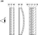
- the virtual reality display device of the present invention can use a curved substrate having a lens shape as a base material (for example, a member between the second retardation layer 12 and the half mirror 40 in FIG. 1).
- the optically absorptive anisotropic layer or laminate of the present invention can be used by processing it into a three-dimensional curved surface.
- Fig. 1 is a side view showing an embodiment of a virtual reality display device according to the present invention.
- 1 includes, from the viewing side, a second absorbing linear polarizer 22, a second retardation layer 12, a half mirror 40, an anti-reflection layer 50, a reflective circular polarizer 30, a positive C plate 60, a first retardation layer 11, a first absorbing linear polarizer 21, a third retardation layer 13, and an image display panel 70, which are arranged in this order.
- the present invention also relates to the following specific polymers.
- the specific polymer of the present invention is a polymer having a repeating unit A-1 represented by formula (A-1), and at least one repeating unit selected from a repeating unit B represented by formula (B) and a repeating unit D represented by formula (D).
- the repeating unit A-1, the repeating unit B and the repeating unit D are all as explained in the specific polymer contained in the liquid crystal composition of the present invention described above, and therefore explanations thereof will be omitted.
- Copolymer B1 was synthesized according to the following procedure.
- methyl ethyl ketone (MEK) was placed in a reaction vessel and heated under a nitrogen gas flow until the internal temperature reached 80° C.
- a methyl ethyl ketone (1.0 g) solution of 0.10 g of 2,2'-azobis(2-methylpropionate)dimethyl was added and stirred at 80° C. for 5 hours to obtain a methyl ethyl ketone solution of copolymer B1.
- the copolymer B1 thus obtained was analyzed by gel permeation chromatography (GPC) and found to have a weight average molecular weight (Mw) of 18,000 (polystyrene equivalent).
- the weight average molecular weight (Mw) was calculated in terms of polystyrene by gel permeation chromatography (EcoSEC HLC-8320GPC (manufactured by Tosoh Corporation) using tetrahydrofuran as an eluent at a flow rate of 0.35 mL/min and a temperature of 40° C.; the columns used were TSKgel SuperHZM-H, TSKgel SuperHZ4000, and TSKgel SuperHZ200 (manufactured by Tosoh Corporation)).
- the Mw of each copolymer described below was measured in the same manner as for copolymer B1.
- Copolymers B2 to B5 and B'3 represented by the formulas described below were obtained in the same manner as in Synthesis Example 1, except that the monomers and composition ratios used in Synthesis Example 1 were changed to monomers and composition ratios that form the repeating units of the copolymer.
- Copolymer B6 was synthesized according to the following procedure.
- MsCl methanesulfonyl chloride
- THF tetrahydrofuran
- DIPEA diisopropylethylamine
- Copolymers B7 to B11 and B'2 represented by the formulas described below were obtained in the same manner as in Synthesis Example 7, except that the monomers and composition ratios used in Synthesis Example 6 were changed to the monomers and composition ratios that form the repeating units of the copolymer.
- Copolymer B12 was synthesized by the following procedure.
- Copolymers B13 and B14 were obtained in the same manner as in Synthesis Example 7, except that the monomers and composition ratios used in Synthesis Example 7 were changed to the monomers and composition ratios forming the repeating units of each copolymer.
- copolymers B1 to B14 and B'2 to B'3 are shown below.
- the numerical value attached to each repeating unit indicates the content (mass%) of each repeating unit relative to the total repeating units (100 mass%) contained in the copolymer.
- TMS represents a trimethylsilyl group
- nBu represents a normal butyl group.
- Example 1-1 [Preparation of Cellulose Acylate Film 1] ⁇ Preparation of cellulose acylate dope for core layer> The following composition was charged into a mixing tank and stirred to dissolve each component, thereby preparing a cellulose acetate solution to be used as a cellulose acylate dope for the core layer.
- the film was further dried by conveying it between rolls of a heat treatment device to prepare an optical film having a thickness of 40 ⁇ m, which was used as Cellulose Acylate Film 1 (Support 1).
- the in-plane retardation of the obtained Cellulose Acylate Film 1 was 0 nm.
- the coating solution PA1 for forming an alignment layer was continuously applied onto the cellulose acylate film 1 using a wire bar.
- the support on which the coating film was formed was dried with hot air at 140° C. for 120 seconds, and then the coating film was irradiated with polarized ultraviolet light (10 mJ/cm 2 , using an ultra-high pressure mercury lamp) to form a photoalignment layer PA1, thereby obtaining a TAC film with a photoalignment layer.
- the thickness of the photoalignment layer PA1 was 0.5 ⁇ m.
- both the polymer liquid crystal compound P1 and the low molecular weight liquid crystal compound L1 are rod-shaped liquid crystal compounds.
- Examples 1-2 to 1-13, Comparative Examples 1-1 to 1-3 Each of the laminates of Examples 1-2 to 1-13 and Comparative Examples 1-1 to 1-3 was obtained in the same manner as in Example 1-1, except that the composition of the liquid crystal composition 1-1 was changed to the composition shown in Table 1 below.
- Examples 1-14 and 1-15 Each of the laminates of Examples 1-14 and 1-15 was obtained in the same manner as in Example 1-1, except that the composition of the liquid crystal composition 1-1 was changed to the composition shown in Table 1 below.
- each repeating unit indicates the content (mass%) of each repeating unit relative to the total repeating units contained in each polymer.
- the high molecular liquid crystal compounds P2 and P3 and the low molecular liquid crystal compounds L2 and L3 are all rod-shaped liquid crystal compounds.
- Low molecular weight liquid crystal compound L3 is a mixture of the following rod-shaped liquid crystal compounds.
- the numbers in the formula below represent mass %, and R represents a group bonded via an oxygen atom.
- Polymer B'1 Polyether modified silicone (Evonik Tego Chemie, product name "FLOW 425")
- Orientation degree: S ((Az0/Ay0)-1)/((Az0/Ay0)+2)
- Az0 represents the absorbance of the optically absorptive anisotropic film for polarized light in the absorption axis direction
- Ay0 represents the absorbance of the optically absorptive anisotropic film for polarized light in the transmission axis direction.
- Orientation degree is 0.95 or more
- B Orientation degree is 0.88 or more and less than 0.95
- C Orientation degree is less than 0.88 Note that, since none of the layer structures other than the optically absorptive anisotropic film in the laminate has absorption in the range of 400 to 700 nm, the orientation degree calculated above can be interpreted as the value of the optically absorptive anisotropic film in the laminate.
- mass ratio to dichroic material means the mass ratio of the copolymer content to the dichroic material content in the liquid crystal composition (copolymer content/dichroic material content).
- Example 1-1 to 1-15 As shown in Table 1, it was shown that by using a liquid crystal composition containing a specific polymer, it is possible to form an optically absorptive anisotropic film in which repelling is suppressed during formation of the film and the occurrence of orientation defects is suppressed. Comparison of Examples 1-1 and 1-2 with Example 1-5 shows that when a specific polymer having a repeating unit B is used, orientation defects (haze) can be further suppressed, and an optically absorptive anisotropic film with excellent orientation can be formed.
- Comparison of Examples 1-6 and 1-7 with Example 1-5 shows that when a specific polymer having a repeating unit D is used, repelling and orientation defects (haze) can be further suppressed, and an optically absorptive anisotropic film having an excellent degree of orientation can be formed.
- Comparison between Examples 1-8 and 1-9 shows that when the sum of the molecular weights of the groups corresponding to R B4 and R B5 in the repeating unit B is 100 or less, orientation defects (haze) can be further suppressed, and an optically absorptive anisotropic film with excellent orientation can be formed.
- Example 1-8 and Example 1-11 shows that when the content of the repeating unit D is 20% by mass or more based on the total mass of the specific polymer, cissing can be further suppressed.
- Comparison between Example 1-8 and Example 1-12 shows that when a polymer liquid crystal compound is used, the orientation defect (haze) can be further suppressed, and an optically absorptive anisotropic film with an excellent degree of orientation can be formed.
- Example 2-1 [Formation of Alignment Film 2] On a cellulose acylate film (TAC substrate having a thickness of 40 ⁇ m: TG40, manufactured by Fujifilm Corporation), the following composition for forming an alignment film 1 was continuously applied with a wire bar. The cellulose acylate film on which the coating film was formed was dried with hot air at 140° C. for 120 seconds to form an alignment film 2, thereby obtaining a TAC film with an alignment film. The thickness of the alignment film 2 was 0.5 ⁇ m.
- ⁇ (Orientation film forming composition 2) ⁇ ⁇ 100.00 parts by mass of polymer PA2 (see below) ⁇ 8.25 parts by mass of acid generator PAG-1 (see below) ⁇ 0.6 parts by mass of stabilizer DIPEA (see below) ⁇ 250.36 parts by mass of methyl ethyl ketone ⁇ 1001.42 parts by mass of butyl acetate
- the transmittance central axis angle ⁇ was measured using the method described above using the laminate 2-1 thus produced, and was found to be 0°. Note that, since none of the layer configurations other than the optically absorbing anisotropic film 2-1 in the laminate 2-1 have any absorption anisotropy, the transmittance central axis angle ⁇ calculated above can be interpreted as the value for the optically absorbing anisotropic film 2-1 in the laminate 2-1.
- Comparative Example 2-1 A laminate of Comparative Example 2-1 was obtained in the same manner as in Example 2-1, except that the copolymer B13 used in the liquid crystal composition 2-1 was changed to the above-mentioned copolymer B'1.
- Example 2-1 The laminates of Example 2-1 and Comparative Example 2-1 were used to evaluate the haze and cissing described above. The results are shown in Table 2.
- Example 2-1 As shown in Table 2, it was shown that by using a liquid crystal composition containing a specific polymer, it is possible to form an optically absorptive anisotropic film in which repelling during formation of the film is suppressed and the occurrence of orientation defects is suppressed (Example 2-1). In contrast, when a liquid crystal composition not containing the specific polymer was used, repelling could not be sufficiently suppressed during the formation of the optically absorptive anisotropic film, and alignment defects in the obtained optically absorptive anisotropic film could not be sufficiently suppressed (Comparative Example 2-1).
- Display devices 1 and 2 were produced by the method described below using the laminate 1-14 produced in Example 1-14, and it was confirmed that the laminate of the present invention functions sufficiently as an optically absorptive anisotropic film.
- a coating solution E1 for forming a photo-alignment film having the following composition was continuously applied with a wire bar onto the above-mentioned cellulose acylate film 1.
- the cellulose acylate film 1 on which the coating film was formed was dried with hot air at 140° C. for 120 seconds, and then the coating film was irradiated with polarized ultraviolet light (10 mJ/cm 2 , using an ultra-high pressure mercury lamp) to form a photo-alignment film E1 with a thickness of 0.2 ⁇ m, thereby obtaining a TAC film with a photo-alignment film.
- Coating liquid E1 for forming photo-alignment film ⁇ 100.00 parts by weight of the polymer PA3 described below; 5.00 parts by weight of the thermal cationic polymerization initiator PAG-1 described above; 0.005 parts by weight of the acid generator CPI-110TF described below; 16.50 parts by weight of isopropyl alcohol; and 1072 parts by weight of butyl acetate. .00 parts by mass Methyl ethyl ketone 268.00 parts by mass ---------------------------------------------------------------------------------------------------------------------------------------------------------------------------------------------------------------------------------------------------------------------------------------------------------------------------------------------------------------------------------------------------------------
- Polymer PA3 (In the following formula, the numerical value for each repeating unit indicates the content (mass%) of each repeating unit relative to the total repeating units. Weight average molecular weight: 45,000)
- the composition F1 having the following composition was applied onto the photo-alignment film E1 using a bar coater.
- the coating film formed on the photo-alignment film E1 was heated to 120°C with hot air, and then cooled to 60°C.
- the coating film was then irradiated with 100mJ/ cm2 ultraviolet light at a wavelength of 365nm using a high-pressure mercury lamp under a nitrogen atmosphere, and then irradiated with 500mJ/ cm2 ultraviolet light while heating to 120°C, thereby fixing the alignment of the liquid crystal compound, and a retardation layer film 1 having a positive A plate F1 was produced.
- the positive A plate F1 had a thickness of 2.5 ⁇ m and an Re(550) of 144 nm.
- the positive A plate satisfied the relationship Re(450) ⁇ Re(550) ⁇ Re(650).
- Re(450)/Re(550) was 0.82.
- the positive A plate corresponds to a so-called ⁇ /4 plate.
- Polymerizable liquid crystal compound LA-1 (tBu represents a tertiary butyl group)
- Polymerizable liquid crystal compound LA-4 (Me represents a methyl group)
- Leveling agent T-1 (In the following formula, the numerical value for each repeating unit indicates the content (mass%) of each repeating unit relative to the total repeating units; weight average molecular weight: 25,000)
- the above-mentioned Cellulose Acylate Film 1 was used as the temporary support.
- the cellulose acylate film 1 was passed through a dielectric heating roll at a temperature of 60°C to raise the surface temperature of the film to 40°C, and then an alkaline solution having the composition shown below was applied to one side of the film in an amount of 14 ml/ m2 using a bar coater, heated to 110°C, and transported under a steam-type far-infrared heater manufactured by Noritake Co., Limited for 10 seconds.
- 3 ml/ m2 of pure water was applied onto the film using the same bar coater.
- the film was transported to a drying zone at 70° C. for 10 seconds and dried, thereby preparing an alkaline saponified cellulose acylate film 1.
- the coating solution G1 for forming an alignment film having the following composition was continuously applied onto the above-mentioned alkaline saponification-treated cellulose acylate film 1 using a #8 wire bar.
- the resulting film was dried with hot air at 60°C for 60 seconds and then with hot air at 100°C for 120 seconds to form an alignment film G1.
- a coating solution H1 for forming a positive C plate having the following composition was applied onto an alignment film G1, and the resulting coating film was aged at 60° C. for 60 seconds.
- the coating film was then irradiated with ultraviolet light at 1000 mJ/cm 2 using an air-cooled metal halide lamp (manufactured by Eye Graphics Co., Ltd.) at 70 mW/cm 2 under air to fix the alignment state, thereby vertically aligning the liquid crystal compound, and a retardation layer film 2 having a positive C plate H1 with a thickness of 0.5 ⁇ m was produced.
- the Rth(550) of the obtained positive C plate was ⁇ 60 nm.
- Compound B03 (In the following formula, the numerical value for each repeating unit indicates the content (mass%) of each repeating unit relative to the total repeating units; weight average molecular weight: 15,000)
- the positive C plate side of the obtained retardation layer film 2 was attached to the liquid crystal surface exposed by peeling off the alignment film with an adhesive, and the support and the alignment layer were peeled off.
- a circular polarizing plate 1 consisting of a light absorption anisotropic film/adhesive layer/positive A plate/adhesive layer/positive C plate was prepared.
- Adhesive 1 20 parts by mass of methylolmelamine was dissolved in pure water at a temperature of 30° C. relative to 100 parts by mass of a polyvinyl alcohol resin containing an acetoacetyl group (average degree of polymerization: 1,200, degree of saponification: 98.5 mol %, degree of acetoacetylation: 5 mol %) to prepare an aqueous solution having a solid content of 3.7% by mass.
- the obtained polyester carbonate resin (pellets) was vacuum dried at 80°C for 5 hours, and then a long resin film with a thickness of 130 ⁇ m was produced using a film-making device equipped with a single-screw extruder (manufactured by Toshiba Machine Co., Ltd., cylinder setting temperature: 250°C), a T-die (width 200 mm, setting temperature: 250°C), a chill roll (setting temperature: 120-130°C) and a winder.
- the obtained long resin film was stretched while adjusting to obtain a predetermined phase difference, and a phase difference film 3 with a thickness of 48 ⁇ m was obtained.
- the stretching conditions were a stretching temperature of 143°C in the width direction and a stretching ratio of 2.8 times.
- the obtained phase difference film 3 had a Re(550) of 141 nm, a Re(450)/Re(550) of 0.86, and an Nz coefficient of 1.12.
- the above phase difference film 3 corresponds to a so-called ⁇ /4
- the laminate (optical film) of the present invention has sufficient performance as an optical compensation film.
Landscapes
- Chemical & Material Sciences (AREA)
- Physics & Mathematics (AREA)
- Health & Medical Sciences (AREA)
- Chemical Kinetics & Catalysis (AREA)
- Medicinal Chemistry (AREA)
- Polymers & Plastics (AREA)
- Organic Chemistry (AREA)
- Optics & Photonics (AREA)
- General Physics & Mathematics (AREA)
- Addition Polymer Or Copolymer, Post-Treatments, Or Chemical Modifications (AREA)
Abstract
本発明の課題は、光吸収異方性膜の形成時にハジキが抑制され、かつ、配向欠陥の発生が抑制された光吸収異方性膜を形成できる液晶組成物、光吸収異方性膜、積層体、画像表示装置及び重合体の提供である。本発明の液晶組成物は、液晶化合物と、二色性物質と、式(A)で表される構造を含む繰り返し単位Aを有する重合体と、を含む。式(A)中、RA1及びRA2はそれぞれ独立に水素原子又はアルキル基、RA3は水素原子、ハロゲン原子又は置換基、Xは式(a)で表される構造を1個以上含む置換基を表し、式(a)中、*は結合位置、Ra1、Ra2及びRa3はそれぞれ独立に、置換基を有していてもよい、アルキル基、アルケニル基、アリール基又はアルキレンアリール基を表す。
Description
本発明は、液晶組成物、光吸収異方性膜、積層体、画像表示装置及び重合体に関する。
光学補償シート及び位相差フィルムなどの光学フィルムは、画像着色解消及び視野角制御などの点から、様々な表示装置で用いられている。
例えば、特許文献1には、位相差フィルムに含まれる位相差層を形成するための組成物として、「液晶化合物と、界面活性剤と、溶剤とを含む、位相差層形成用組成物の硬化物からなり、前記界面活性剤が、下記一般式(I)で表される繰り返し単位を有するポリエーテル変性シリコーンである」ことが記載されている(特許文献1の請求項1)。
表示装置に用いられる光学フィルムとして、液晶化合物及び二色性物質を含む光吸収異方性膜が知られている。
本発明者らは、特許文献1に記載されたようなポリエーテル変性シリコーンと、液晶化合物と、二色性物質と、を含む液晶組成物について検討したところ、光吸収異方性膜の形成時にハジキが発生し、また、形成される光吸収異方性膜に配向欠陥が生じることを明らかとした。
本発明者らは、特許文献1に記載されたようなポリエーテル変性シリコーンと、液晶化合物と、二色性物質と、を含む液晶組成物について検討したところ、光吸収異方性膜の形成時にハジキが発生し、また、形成される光吸収異方性膜に配向欠陥が生じることを明らかとした。
そこで、本発明は、光吸収異方性膜の形成時にハジキが抑制され、かつ、配向欠陥の発生が抑制された光吸収異方性膜を形成できる液晶組成物、光吸収異方性膜、積層体、画像表示装置及び重合体の提供を課題とする。
本発明者らは、上記課題を解決すべく鋭意検討した結果、光吸収異方性膜の形成に使用する液晶組成物に所定の重合体を配合することにより、光吸収異方性膜の形成時にハジキが抑制され、かつ、配向欠陥の発生が抑制された光吸収異方性膜を形成できることを見出し、本発明を完成させた。
すなわち、本発明者らは、以下の構成により上記課題が解決できることを見出した。
すなわち、本発明者らは、以下の構成により上記課題が解決できることを見出した。
[1]
液晶化合物と、二色性物質と、後述の式(A)で表される構造を含む繰り返し単位Aを有する重合体と、を含む、液晶組成物。
式(A)中、
RA1及びRA2はそれぞれ独立に、水素原子又はアルキル基を表す。
RA3は、水素原子、ハロゲン原子、又は置換基を表す。
Xは、後述の式(a)で表される構造を1個以上含む置換基を表す。
式(a)中、
*は結合位置を表す。
Ra1、Ra2及びRa3はそれぞれ独立に、置換基を有していてもよい、アルキル基、アルケニル基、アリール基又はアルキレンアリール基を表す。
[2]
上記重合体が、後述の式(B)で表される繰り返し単位Bを更に有する、[1]に記載の液晶組成物。
式(B)中、
RB1、RB2及びRB3はそれぞれ独立に、水素原子、ハロゲン原子、シアノ基、アルキル基、アルケニル基又はアリール基を表す。
RB4及びRB5はそれぞれ独立に、水素原子又は置換基を表す。RB4及びRB5が置換基である場合、RB4及びRB5は連結して環を形成していてもよい。
[3]
上記式(B)において、RB4及びRB5の分子量の合計が100以下である、[2]に記載の液晶組成物。
[4]
上記式(B)中、RB4及びRB5がそれぞれ独立に、水素原子又は炭素数1~15の有機基である、[2]又は[3]に記載の液晶組成物。
[5]
上記重合体が、後述の式(D)で表される繰り返し単位Dを更に有する、[1]~[4]のいずれかに記載の液晶組成物。
式(D)中、
RD1、RD2及びRD3はそれぞれ独立に、水素原子、ハロゲン原子、シアノ基、アルキル基、アルケニル基、又は、アリール基を表す。
LD1は、単結合、-COO-又は-CO-を表す。
SpD1は、炭素数1~20の2価の炭化水素基を表す。ただし、上記炭化水素基の一部を構成する-CH2-のうち、1個又は隣接しない2個以上の-CH2-はそれぞれ独立に、-O-、-S-、-NH-又は-N(Q)-で置換されていてもよく、Qは、置換基を表す。
LD2及びLD3はそれぞれ独立に、単結合又は2価の連結基を表す。
CyDは、メソゲン基を含む2価の連結基を表す。
Dは、水素原子と第14~16族の非金属原子とで構成される水素結合性基を表す。ただし、上記非金属原子は、置換基を有していてもよい。
nは、1~3の整数を表す。nが2又は3である場合、複数のLD2は、それぞれ同一であっても異なっていてもよく、複数のCyDは、それぞれ同一であっても異なっていてもよい。
[6]
上記式(D)中、LD3が単結合を表し、Dが-COOH、-NHCOR2又は-CONHR3を表す、[5]に記載の液晶組成物。
ここで、R2及びR3はそれぞれ独立に、炭素数1~10のアルキル基又はアルケニル基を表す。ただし、上記アルキル基及び上記アルケニル基の一部を構成する-CH2-のうち、1個又は隣接しない2個以上の-CH2-は、-O-で置換されていてもよい。
[7]
上記式(D)中、LD3が単結合を表し、Dが-NHCOR4を表す、[5]又は[6]に記載の液晶組成物。
ここで、R4は、炭素数1~3のアルキル基又はアルケニル基を表す。ただし、上記アルキル基及び上記アルケニル基の一部を構成する-CH2-のうち、1個又は隣接しない2個以上の-CH2-は、-O-で置換されていてもよい。
[8]
上記式(D)中、nが1又は2である、[5]~[7]のいずれかに記載の液晶組成物。
[9]
上記繰り返し単位Aが、後述の式(A-1)で表される繰り返し単位A-1である、[1]~[8]のいずれかに記載の液晶組成物。
式(A-1)中、
RA1及びRA2はそれぞれ独立に、水素原子又はアルキル基を表す。
RA3は、水素原子、ハロゲン原子又は置換基を表す。
LA1は、単結合、-O-又は-NRZ-を表す。ただし、RZは、水素原子又は置換基を表す。
LA2は、単結合又はm+1価の連結基を表す。
mは、1以上の整数を表す。
Ra1、Ra2及びRa3はそれぞれ独立に、置換基を有していてもよい、アルキル基、アルケニル基、アリール基又はアルキレンアリール基を表す。
mが2以上の整数である場合、複数のRa1は、それぞれ同一であっても異なっていてもよく、複数のRa2は、それぞれ同一であっても異なっていてもよく、複数のRa3は、それぞれ同一であっても異なっていてもよい。
[10]
上記式(A-1)中、mが2以上の整数である、[9]に記載の液晶組成物。
[11]
上記重合体が、後述の式(A-1)で表される繰り返し単位A-1、後述の式(B)で表される繰り返し単位B、及び、後述の式(D)で表される繰り返し単位Dを有する、[1]~[10]のいずれかに記載の液晶組成物。
式(A-1)中、
RA1及びRA2はそれぞれ独立に、水素原子又はアルキル基を表す。
RA3は、水素原子、ハロゲン原子又は置換基を表す。
LA1は、単結合、-O-又は-NRZ-を表す。ただし、RZは、水素原子又は置換基を表す。
LA2は、単結合又はm+1価の連結基を表す。
mは、1以上の整数を表す。
Ra1、Ra2及びRa3はそれぞれ独立に、置換基を有していてもよい、アルキル基、アルケニル基、アリール基又はアルキレンアリール基を表す。
mが2以上の整数である場合、複数のRa1は、それぞれ同一であっても異なっていてもよく、複数のRa2は、それぞれ同一であっても異なっていてもよく、複数のRa3は、それぞれ同一であっても異なっていてもよい。
式(B)中、
RB1、RB2及びRB3はそれぞれ独立に、水素原子、ハロゲン原子、シアノ基、アルキル基、アルケニル基、又は、アリール基を表す。
RB4及びRB5はそれぞれ独立に、水素原子又は置換基を表す。RB4及びRB5が置換基である場合、RB4及びRB5は連結して環を形成していてもよい。
式(D)中、
RD1、RD2及びRD3はそれぞれ独立に、水素原子、ハロゲン原子、シアノ基、アルキル基、アルケニル基、又は、アリール基を表す。
LD1は、単結合、-COO-、又は、-CO-を表す。
SpD1は、炭素数1~20の2価の炭化水素基を表す。ただし、上記炭化水素基の一部を構成する-CH2-のうち、1個又は隣接しない2個以上の-CH2-はそれぞれ独立に、-O-、-S-、-NH-、又は、-N(Q)-で置換されていてもよく、Qは、置換基を表す。
LD2及びLD3はそれぞれ独立に、単結合、又は、2価の連結基を表す。
CyDはメソゲン基を含む2価の連結基を表す。
Dは、水素原子と第14~16族の非金属原子とで構成される水素結合性基を表す。ただし、上記非金属原子は、置換基を有していてもよい。
nは、1~3の整数を表す。nが2又は3である場合、複数のLD2は、それぞれ同一であっても異なっていてもよく、複数のCyDは、それぞれ同一であっても異なっていてもよい。
[12]
上記二色性物質の含有量に対する、上記重合体の含有量の質量比が、0.0007~0.6である、[1]~[11]のいずれかに記載の液晶組成物。
[13]
上記液晶化合物が、高分子液晶化合物を含む、[1]~[12]のいずれかに記載の液晶組成物。
[14]
上記液晶化合物が、低分子液晶化合物を更に含む、[13]に記載の液晶組成物。
[15]
[1]~[14]のいずれかに記載の液晶組成物を用いて得られる、光吸収異方性膜。
[16]
上記光吸収異方性膜に含まれる液晶化合物及び二色性物質の配向状態が固定化されており、
上記光吸収異方性膜の透過率中心軸と、上記光吸収異方性膜表面の法線方向とのなす角度θが45°超90°以下である、[15]に記載の光吸収異方性膜。
[17]
[15]又は[16]に記載の光吸収異方性膜と、λ/4板と、を有する、積層体。
[18]
[15]又は[16]に記載の光吸収異方性膜と、表示素子と、を有する、画像表示装置。
[19]
後述の式(A-1)で表される繰り返し単位A-1と、
後述の式(B)で表される繰り返し単位B、及び、後述の式(D)で表される繰り返し単位Dの少なくとも一方の繰り返し単位と、を有する、重合体。
式(A-1)中、
RA1及びRA2はそれぞれ独立に、水素原子又はアルキル基を表す。
RA3は、水素原子、ハロゲン原子又は置換基を表す。
LA1は、単結合、-O-又は-NRZ-を表す。ただし、RZは、水素原子又は置換基を表す。
LA2は、単結合又はm+1価の連結基を表す。
mは、1以上の整数を表す。
Ra1、Ra2及びRa3はそれぞれ独立に、置換基を有していてもよい、アルキル基、アルケニル基、アリール基又はアルキレンアリール基を表す。
mが2以上の整数である場合、複数のRa1は、それぞれ同一であっても異なっていてもよく、複数のRa2は、それぞれ同一であっても異なっていてもよく、複数のRa3は、それぞれ同一であっても異なっていてもよい。
式(B)中、
RB1、RB2及びRB3はそれぞれ独立に、水素原子、ハロゲン原子、シアノ基、アルキル基、アルケニル基、又は、アリール基を表す。
RB4及びRB5はそれぞれ独立に、水素原子又は置換基を表す。RB4及びRB5が置換基である場合、RB4及びRB5は連結して環を形成していてもよい。
式(D)中、
RD1、RD2及びRD3はそれぞれ独立に、水素原子、ハロゲン原子、シアノ基、アルキル基、アルケニル基、又は、アリール基を表す。
LD1は、単結合、-COO-、又は、-CO-を表す。
SpD1は、炭素数1~20の2価の炭化水素基を表す。ただし、上記炭化水素基の一部を構成する-CH2-のうち、1個又は隣接しない2個以上の-CH2-はそれぞれ独立に、-O-、-S-、-NH-、又は、-N(Q)-で置換されていてもよく、Qは、置換基を表す。
LD2及びLD3はそれぞれ独立に、単結合、又は、2価の連結基を表す。
CyDはメソゲン基を含む2価の連結基を表す。
Dは、水素原子と第14~16族の非金属原子とで構成される水素結合性基を表す。ただし、上記非金属原子は、置換基を有していてもよい。
nは、1~3の整数を表す。nが2又は3である場合、複数のLD2は、それぞれ同一であっても異なっていてもよく、複数のCyDは、それぞれ同一であっても異なっていてもよい。
液晶化合物と、二色性物質と、後述の式(A)で表される構造を含む繰り返し単位Aを有する重合体と、を含む、液晶組成物。
式(A)中、
RA1及びRA2はそれぞれ独立に、水素原子又はアルキル基を表す。
RA3は、水素原子、ハロゲン原子、又は置換基を表す。
Xは、後述の式(a)で表される構造を1個以上含む置換基を表す。
式(a)中、
*は結合位置を表す。
Ra1、Ra2及びRa3はそれぞれ独立に、置換基を有していてもよい、アルキル基、アルケニル基、アリール基又はアルキレンアリール基を表す。
[2]
上記重合体が、後述の式(B)で表される繰り返し単位Bを更に有する、[1]に記載の液晶組成物。
式(B)中、
RB1、RB2及びRB3はそれぞれ独立に、水素原子、ハロゲン原子、シアノ基、アルキル基、アルケニル基又はアリール基を表す。
RB4及びRB5はそれぞれ独立に、水素原子又は置換基を表す。RB4及びRB5が置換基である場合、RB4及びRB5は連結して環を形成していてもよい。
[3]
上記式(B)において、RB4及びRB5の分子量の合計が100以下である、[2]に記載の液晶組成物。
[4]
上記式(B)中、RB4及びRB5がそれぞれ独立に、水素原子又は炭素数1~15の有機基である、[2]又は[3]に記載の液晶組成物。
[5]
上記重合体が、後述の式(D)で表される繰り返し単位Dを更に有する、[1]~[4]のいずれかに記載の液晶組成物。
式(D)中、
RD1、RD2及びRD3はそれぞれ独立に、水素原子、ハロゲン原子、シアノ基、アルキル基、アルケニル基、又は、アリール基を表す。
LD1は、単結合、-COO-又は-CO-を表す。
SpD1は、炭素数1~20の2価の炭化水素基を表す。ただし、上記炭化水素基の一部を構成する-CH2-のうち、1個又は隣接しない2個以上の-CH2-はそれぞれ独立に、-O-、-S-、-NH-又は-N(Q)-で置換されていてもよく、Qは、置換基を表す。
LD2及びLD3はそれぞれ独立に、単結合又は2価の連結基を表す。
CyDは、メソゲン基を含む2価の連結基を表す。
Dは、水素原子と第14~16族の非金属原子とで構成される水素結合性基を表す。ただし、上記非金属原子は、置換基を有していてもよい。
nは、1~3の整数を表す。nが2又は3である場合、複数のLD2は、それぞれ同一であっても異なっていてもよく、複数のCyDは、それぞれ同一であっても異なっていてもよい。
[6]
上記式(D)中、LD3が単結合を表し、Dが-COOH、-NHCOR2又は-CONHR3を表す、[5]に記載の液晶組成物。
ここで、R2及びR3はそれぞれ独立に、炭素数1~10のアルキル基又はアルケニル基を表す。ただし、上記アルキル基及び上記アルケニル基の一部を構成する-CH2-のうち、1個又は隣接しない2個以上の-CH2-は、-O-で置換されていてもよい。
[7]
上記式(D)中、LD3が単結合を表し、Dが-NHCOR4を表す、[5]又は[6]に記載の液晶組成物。
ここで、R4は、炭素数1~3のアルキル基又はアルケニル基を表す。ただし、上記アルキル基及び上記アルケニル基の一部を構成する-CH2-のうち、1個又は隣接しない2個以上の-CH2-は、-O-で置換されていてもよい。
[8]
上記式(D)中、nが1又は2である、[5]~[7]のいずれかに記載の液晶組成物。
[9]
上記繰り返し単位Aが、後述の式(A-1)で表される繰り返し単位A-1である、[1]~[8]のいずれかに記載の液晶組成物。
式(A-1)中、
RA1及びRA2はそれぞれ独立に、水素原子又はアルキル基を表す。
RA3は、水素原子、ハロゲン原子又は置換基を表す。
LA1は、単結合、-O-又は-NRZ-を表す。ただし、RZは、水素原子又は置換基を表す。
LA2は、単結合又はm+1価の連結基を表す。
mは、1以上の整数を表す。
Ra1、Ra2及びRa3はそれぞれ独立に、置換基を有していてもよい、アルキル基、アルケニル基、アリール基又はアルキレンアリール基を表す。
mが2以上の整数である場合、複数のRa1は、それぞれ同一であっても異なっていてもよく、複数のRa2は、それぞれ同一であっても異なっていてもよく、複数のRa3は、それぞれ同一であっても異なっていてもよい。
[10]
上記式(A-1)中、mが2以上の整数である、[9]に記載の液晶組成物。
[11]
上記重合体が、後述の式(A-1)で表される繰り返し単位A-1、後述の式(B)で表される繰り返し単位B、及び、後述の式(D)で表される繰り返し単位Dを有する、[1]~[10]のいずれかに記載の液晶組成物。
式(A-1)中、
RA1及びRA2はそれぞれ独立に、水素原子又はアルキル基を表す。
RA3は、水素原子、ハロゲン原子又は置換基を表す。
LA1は、単結合、-O-又は-NRZ-を表す。ただし、RZは、水素原子又は置換基を表す。
LA2は、単結合又はm+1価の連結基を表す。
mは、1以上の整数を表す。
Ra1、Ra2及びRa3はそれぞれ独立に、置換基を有していてもよい、アルキル基、アルケニル基、アリール基又はアルキレンアリール基を表す。
mが2以上の整数である場合、複数のRa1は、それぞれ同一であっても異なっていてもよく、複数のRa2は、それぞれ同一であっても異なっていてもよく、複数のRa3は、それぞれ同一であっても異なっていてもよい。
式(B)中、
RB1、RB2及びRB3はそれぞれ独立に、水素原子、ハロゲン原子、シアノ基、アルキル基、アルケニル基、又は、アリール基を表す。
RB4及びRB5はそれぞれ独立に、水素原子又は置換基を表す。RB4及びRB5が置換基である場合、RB4及びRB5は連結して環を形成していてもよい。
式(D)中、
RD1、RD2及びRD3はそれぞれ独立に、水素原子、ハロゲン原子、シアノ基、アルキル基、アルケニル基、又は、アリール基を表す。
LD1は、単結合、-COO-、又は、-CO-を表す。
SpD1は、炭素数1~20の2価の炭化水素基を表す。ただし、上記炭化水素基の一部を構成する-CH2-のうち、1個又は隣接しない2個以上の-CH2-はそれぞれ独立に、-O-、-S-、-NH-、又は、-N(Q)-で置換されていてもよく、Qは、置換基を表す。
LD2及びLD3はそれぞれ独立に、単結合、又は、2価の連結基を表す。
CyDはメソゲン基を含む2価の連結基を表す。
Dは、水素原子と第14~16族の非金属原子とで構成される水素結合性基を表す。ただし、上記非金属原子は、置換基を有していてもよい。
nは、1~3の整数を表す。nが2又は3である場合、複数のLD2は、それぞれ同一であっても異なっていてもよく、複数のCyDは、それぞれ同一であっても異なっていてもよい。
[12]
上記二色性物質の含有量に対する、上記重合体の含有量の質量比が、0.0007~0.6である、[1]~[11]のいずれかに記載の液晶組成物。
[13]
上記液晶化合物が、高分子液晶化合物を含む、[1]~[12]のいずれかに記載の液晶組成物。
[14]
上記液晶化合物が、低分子液晶化合物を更に含む、[13]に記載の液晶組成物。
[15]
[1]~[14]のいずれかに記載の液晶組成物を用いて得られる、光吸収異方性膜。
[16]
上記光吸収異方性膜に含まれる液晶化合物及び二色性物質の配向状態が固定化されており、
上記光吸収異方性膜の透過率中心軸と、上記光吸収異方性膜表面の法線方向とのなす角度θが45°超90°以下である、[15]に記載の光吸収異方性膜。
[17]
[15]又は[16]に記載の光吸収異方性膜と、λ/4板と、を有する、積層体。
[18]
[15]又は[16]に記載の光吸収異方性膜と、表示素子と、を有する、画像表示装置。
[19]
後述の式(A-1)で表される繰り返し単位A-1と、
後述の式(B)で表される繰り返し単位B、及び、後述の式(D)で表される繰り返し単位Dの少なくとも一方の繰り返し単位と、を有する、重合体。
式(A-1)中、
RA1及びRA2はそれぞれ独立に、水素原子又はアルキル基を表す。
RA3は、水素原子、ハロゲン原子又は置換基を表す。
LA1は、単結合、-O-又は-NRZ-を表す。ただし、RZは、水素原子又は置換基を表す。
LA2は、単結合又はm+1価の連結基を表す。
mは、1以上の整数を表す。
Ra1、Ra2及びRa3はそれぞれ独立に、置換基を有していてもよい、アルキル基、アルケニル基、アリール基又はアルキレンアリール基を表す。
mが2以上の整数である場合、複数のRa1は、それぞれ同一であっても異なっていてもよく、複数のRa2は、それぞれ同一であっても異なっていてもよく、複数のRa3は、それぞれ同一であっても異なっていてもよい。
式(B)中、
RB1、RB2及びRB3はそれぞれ独立に、水素原子、ハロゲン原子、シアノ基、アルキル基、アルケニル基、又は、アリール基を表す。
RB4及びRB5はそれぞれ独立に、水素原子又は置換基を表す。RB4及びRB5が置換基である場合、RB4及びRB5は連結して環を形成していてもよい。
式(D)中、
RD1、RD2及びRD3はそれぞれ独立に、水素原子、ハロゲン原子、シアノ基、アルキル基、アルケニル基、又は、アリール基を表す。
LD1は、単結合、-COO-、又は、-CO-を表す。
SpD1は、炭素数1~20の2価の炭化水素基を表す。ただし、上記炭化水素基の一部を構成する-CH2-のうち、1個又は隣接しない2個以上の-CH2-はそれぞれ独立に、-O-、-S-、-NH-、又は、-N(Q)-で置換されていてもよく、Qは、置換基を表す。
LD2及びLD3はそれぞれ独立に、単結合、又は、2価の連結基を表す。
CyDはメソゲン基を含む2価の連結基を表す。
Dは、水素原子と第14~16族の非金属原子とで構成される水素結合性基を表す。ただし、上記非金属原子は、置換基を有していてもよい。
nは、1~3の整数を表す。nが2又は3である場合、複数のLD2は、それぞれ同一であっても異なっていてもよく、複数のCyDは、それぞれ同一であっても異なっていてもよい。
本発明によれば、光吸収異方性膜の形成時にハジキが抑制され、かつ、配向欠陥の発生が抑制された光吸収異方性膜を形成できる液晶組成物、光吸収異方性膜、積層体、画像表示装置及び重合体を提供できる。
以下、本発明について詳細に説明する。
以下に記載する構成要件の説明は、本発明の代表的な実施態様に基づいてなされることがあるが、本発明はそのような実施態様に限定されるものではない。
なお、本明細書において、「~」を用いて表される数値範囲は、「~」の前後に記載される数値を下限値及び上限値として含む範囲を意味する。本明細書に段階的に記載されている数値範囲において、ある数値範囲で記載された上限値又は下限値は、他の段階的な記載の数値範囲の上限値又は下限値に置き換えてもよい。また、本明細書に記載されている数値範囲において、ある数値範囲で記載された上限値又は下限値は、実施例に示されている値に置き換えてもよい。
また、本明細書において、各成分は、各成分に該当する物質を1種単独で用いても、2種以上を併用してもよい。ここで、各成分について2種以上の物質を併用する場合、その成分についての含有量とは、特段の断りが無い限り、併用した物質の合計の含有量を指す。
また、本明細書において、「(メタ)アクリレート」は、「アクリレート」又は「メタクリレート」を表す表記であり、「(メタ)アクリル」は、「アクリル」又は「メタクリル」を表す表記であり、「(メタ)アクリロイル」は、「アクリロイル」又は「メタクリロイル」を表す表記であり、「(メタ)アクリル酸」は、「アクリル酸」又は「メタクリル酸」を表す表記である。
また、本明細書において表記される2価の基の結合方向は、特段の断りがない限り、制限されない。例えば、「X-Y-Z」なる式で表される化合物中の、Yが-C(O)-O-である場合、Yは、-C(O)-O-であってもよく、-O-C(O)-であってもよい。また、上記化合物は「X-C(O)-O-Z」であってもよく「X-O-C(O)-Z」であってもよい。
以下に記載する構成要件の説明は、本発明の代表的な実施態様に基づいてなされることがあるが、本発明はそのような実施態様に限定されるものではない。
なお、本明細書において、「~」を用いて表される数値範囲は、「~」の前後に記載される数値を下限値及び上限値として含む範囲を意味する。本明細書に段階的に記載されている数値範囲において、ある数値範囲で記載された上限値又は下限値は、他の段階的な記載の数値範囲の上限値又は下限値に置き換えてもよい。また、本明細書に記載されている数値範囲において、ある数値範囲で記載された上限値又は下限値は、実施例に示されている値に置き換えてもよい。
また、本明細書において、各成分は、各成分に該当する物質を1種単独で用いても、2種以上を併用してもよい。ここで、各成分について2種以上の物質を併用する場合、その成分についての含有量とは、特段の断りが無い限り、併用した物質の合計の含有量を指す。
また、本明細書において、「(メタ)アクリレート」は、「アクリレート」又は「メタクリレート」を表す表記であり、「(メタ)アクリル」は、「アクリル」又は「メタクリル」を表す表記であり、「(メタ)アクリロイル」は、「アクリロイル」又は「メタクリロイル」を表す表記であり、「(メタ)アクリル酸」は、「アクリル酸」又は「メタクリル酸」を表す表記である。
また、本明細書において表記される2価の基の結合方向は、特段の断りがない限り、制限されない。例えば、「X-Y-Z」なる式で表される化合物中の、Yが-C(O)-O-である場合、Yは、-C(O)-O-であってもよく、-O-C(O)-であってもよい。また、上記化合物は「X-C(O)-O-Z」であってもよく「X-O-C(O)-Z」であってもよい。
また、本明細書において、角度に関する「直交」および「平行」とは、厳密な角度±10°の範囲を意味するものとし、角度に関する「同一」および「異なる」は、その差が5°未満であるか否かを基準に判断できる。
また、本明細書において、「可視光」とは、380~780nmのことをいう。
また、本明細書において、測定波長について特に付記がない場合は、測定波長は550nmである。
また、本明細書において、「可視光」とは、380~780nmのことをいう。
また、本明細書において、測定波長について特に付記がない場合は、測定波長は550nmである。
本明細書において、「遅相軸」とは、面内において屈折率が最大となる方向を意味する。なお、光学異方性層の遅相軸という場合は、光学異方性層全体の遅相軸を意図する。
本明細書において、「Re(λ)」および「Rth(λ)」は、それぞれ、波長λにおける面内のレターデーション、および、厚さ方向のレターデーションを表す。
ここで、面内レターデーションおよび厚み方向のレターデーションの値は、AxoScan OPMF-1(オプトサイエンス社製)を用い、測定波長の光を用いて測定した値をいう。
具体的には、AxoScan OPMF-1にて、平均屈折率((nx+ny+nz)/3)と膜厚(d(μm))を入力することにより、
遅相軸方向(°)
Re(λ)=R0(λ)
Rth(λ)=((nx+ny)/2-nz)×d
が算出される。
なお、R0(λ)は、AxoScan OPMF-1で算出される数値として表示されるものであるが、Re(λ)を意味している。
ここで、面内レターデーションおよび厚み方向のレターデーションの値は、AxoScan OPMF-1(オプトサイエンス社製)を用い、測定波長の光を用いて測定した値をいう。
具体的には、AxoScan OPMF-1にて、平均屈折率((nx+ny+nz)/3)と膜厚(d(μm))を入力することにより、
遅相軸方向(°)
Re(λ)=R0(λ)
Rth(λ)=((nx+ny)/2-nz)×d
が算出される。
なお、R0(λ)は、AxoScan OPMF-1で算出される数値として表示されるものであるが、Re(λ)を意味している。
[置換基W]
本明細書で用いられる置換基Wは、以下の基を表す。
置換基Wとしては、例えば、ハロゲン原子、炭素数1~20のアルキル基、炭素数1~20のハロゲン化アルキル基、炭素数1~20のシクロアルキル基、炭素数1~10のアルキルカルボニル基、炭素数1~10のアルキルオキシカルボニル基、炭素数1~10のアルキルカルボニルオキシ基、炭素数1~10のアルキルアミノ基、アルキルアミノカルボニル基、炭素数1~20のアルコキシ基、炭素数1~20のアルケニル基、炭素数1~20のアルキニル基、炭素数1~20のアリール基、複素環基(ヘテロ環基といってもよい)、シアノ基、ヒドロキシ基、ニトロ基、カルボキシ基、アリールオキシ基、シリルオキシ基、ヘテロ環オキシ基、アシルオキシ基、カルバモイルオキシ基、アルコキシカルボニルオキシ基、アリールオキシカルボニルオキシ基、アミノ基(アニリノ基を含む)、アンモニオ基、アシルアミノ基、アミノカルボニルアミノ基、アルコキシカルボニルアミノ基、アリールオキシカルボニルアミノ基、スルファモイルアミノ基、アルキル又はアリールスルホニルアミノ基、メルカプト基、アルキルチオ基、アリールチオ基、ヘテロ環チオ基、スルファモイル基、スルホ基、アルキル又はアリールスルフィニル基、アルキル又はアリールスルホニル基、アシル基、アリールオキシカルボニル基、アルコキシカルボニル基、カルバモイル基、アリール又はヘテロ環アゾ基、イミド基、ホスフィノ基、ホスフィニル基、ホスフィニルオキシ基、ホスフィニルアミノ基、ホスホノ基、シリル基、ヒドラジノ基、ウレイド基、ボロン酸基(-B(OH)2)、ホスファト基(-OPO(OH)2)、スルファト基(-OSO3H)、その他の公知の置換基などが挙げられる。
なお、置換基の詳細については、特開2007-234651号公報の段落[0023]に記載される。
また、置換基Wは、下記式(W1)で表される基であってもよい。
本明細書で用いられる置換基Wは、以下の基を表す。
置換基Wとしては、例えば、ハロゲン原子、炭素数1~20のアルキル基、炭素数1~20のハロゲン化アルキル基、炭素数1~20のシクロアルキル基、炭素数1~10のアルキルカルボニル基、炭素数1~10のアルキルオキシカルボニル基、炭素数1~10のアルキルカルボニルオキシ基、炭素数1~10のアルキルアミノ基、アルキルアミノカルボニル基、炭素数1~20のアルコキシ基、炭素数1~20のアルケニル基、炭素数1~20のアルキニル基、炭素数1~20のアリール基、複素環基(ヘテロ環基といってもよい)、シアノ基、ヒドロキシ基、ニトロ基、カルボキシ基、アリールオキシ基、シリルオキシ基、ヘテロ環オキシ基、アシルオキシ基、カルバモイルオキシ基、アルコキシカルボニルオキシ基、アリールオキシカルボニルオキシ基、アミノ基(アニリノ基を含む)、アンモニオ基、アシルアミノ基、アミノカルボニルアミノ基、アルコキシカルボニルアミノ基、アリールオキシカルボニルアミノ基、スルファモイルアミノ基、アルキル又はアリールスルホニルアミノ基、メルカプト基、アルキルチオ基、アリールチオ基、ヘテロ環チオ基、スルファモイル基、スルホ基、アルキル又はアリールスルフィニル基、アルキル又はアリールスルホニル基、アシル基、アリールオキシカルボニル基、アルコキシカルボニル基、カルバモイル基、アリール又はヘテロ環アゾ基、イミド基、ホスフィノ基、ホスフィニル基、ホスフィニルオキシ基、ホスフィニルアミノ基、ホスホノ基、シリル基、ヒドラジノ基、ウレイド基、ボロン酸基(-B(OH)2)、ホスファト基(-OPO(OH)2)、スルファト基(-OSO3H)、その他の公知の置換基などが挙げられる。
なお、置換基の詳細については、特開2007-234651号公報の段落[0023]に記載される。
また、置換基Wは、下記式(W1)で表される基であってもよい。
式(W1)中、LWは単結合又は2価の連結基を表し、SPWは2価のスペーサー基を表し、Qは末端基を表し、*は結合位置を表す。
LWが表す2価の連結基としては、-O-、-Si(CH3)2-、-(Si(CH3)2O)g-(gは1~10の整数を表す。)、-N(Z)-、-C(Z)=C(Z1)-、-C(Z)=N-、-C(O)-、-C(O)O-、-O-C(O)O-、-C(O)N(Z)-、-C(Z)=C(Z1)-C(O)O-、-C(Z)=N-、-C(Z)=C(Z1)-C(O)N(Z2)-、-C(Z)=C(Z1)-C(O)-S-、-C(Z)=N-N=C(Z1)-(Z、Z1及びZ2はそれぞれ独立に、水素、炭素数1~4のアルキル基、シクロアルキル基、アリール基、シアノ基、又は、ハロゲン原子を表す。)、-C≡C-、-N=N-、-S-、-S(O)-、-S(O)(O)-、-(O)S(O)O-、-O(O)S(O)O-、及び、-SC(O)-などが挙げられる。LWは、これらの基を2つ以上組み合わせた基であってもよい(以下「L-C」とも省略する)。
SPWが表す2価のスペーサー基としては、炭素数1~50の直鎖、分岐若しくは環状のアルキレン基、又は、炭素数1~20複素環基が挙げられる。
上記アルキレン基、複素環基の炭素原子は、-O-、-Si(CH3)2-、-(Si(CH3)2O)g-(gは1~10の整数を表す。)、-N(Z)-、-C(Z)=C(Z1)-、-C(Z)=N-、-C(Z)2-C(Z1)2-、-C(O)-、-C(O)O-、-O-C(O)O-、-C(O)N(Z)-、-C(Z)=C(Z1)-C(O)O-、-C(Z)=N-、-C(Z)=C(Z1)-C(O)N(Z2)-、-C(Z)=C(Z1)-C(O)-S-、-C(Z)=N-N=C(Z1)-(Z、Z1、Z2は独立に、水素、炭素数1~4のアルキル基、シクロアルキル基、アリール基、シアノ基、又は、ハロゲン原子を表す。)、-C≡C-、-N=N-、-S-、-C(S)-、-S(O)-、-SO2-、-(O)S(O)O-、-O(O)S(O)O-、-SC(O)-、及び、これらの基を2つ以上組み合わせた基で置換されていてもよい。
上記アルキレン基の水素原子、及び、複素環基の水素原子は、ハロゲン原子、シアノ基、-ZH1、-OH、-OZH1、-COOH、-C(O)ZH1、-C(O)OZH1、-OC(O)ZH1、-OC(O)OZH1、-NZH1ZH2、-NZH1C(O)ZH2、-NZH1C(O)OZH2、-C(O)NZH1ZH2、-OC(O)NZH1ZH2、-NZH1C(O)NZH2OZH3、-SH、-SZH1、-C(S)ZH1、-C(O)SZH1、-SC(O)ZH1、で置換されていてもよい。ここで、ZH1、ZH2、ZH3は炭素数1~10のアルキル基、ハロゲン化アルキル基、-L-CLを表す。
-L-CLにおいて、Lは単結合又は2価の連結基を表す。2価の連結基の具体例は、上述したLW及びSPWと同じである。
-L-CLにおいて、CLは架橋性基を表す。架橋性基の具体例としては、下記式(P-1)~(P-30)で表される架橋性基が挙げられる。
上記アルキレン基、複素環基の炭素原子は、-O-、-Si(CH3)2-、-(Si(CH3)2O)g-(gは1~10の整数を表す。)、-N(Z)-、-C(Z)=C(Z1)-、-C(Z)=N-、-C(Z)2-C(Z1)2-、-C(O)-、-C(O)O-、-O-C(O)O-、-C(O)N(Z)-、-C(Z)=C(Z1)-C(O)O-、-C(Z)=N-、-C(Z)=C(Z1)-C(O)N(Z2)-、-C(Z)=C(Z1)-C(O)-S-、-C(Z)=N-N=C(Z1)-(Z、Z1、Z2は独立に、水素、炭素数1~4のアルキル基、シクロアルキル基、アリール基、シアノ基、又は、ハロゲン原子を表す。)、-C≡C-、-N=N-、-S-、-C(S)-、-S(O)-、-SO2-、-(O)S(O)O-、-O(O)S(O)O-、-SC(O)-、及び、これらの基を2つ以上組み合わせた基で置換されていてもよい。
上記アルキレン基の水素原子、及び、複素環基の水素原子は、ハロゲン原子、シアノ基、-ZH1、-OH、-OZH1、-COOH、-C(O)ZH1、-C(O)OZH1、-OC(O)ZH1、-OC(O)OZH1、-NZH1ZH2、-NZH1C(O)ZH2、-NZH1C(O)OZH2、-C(O)NZH1ZH2、-OC(O)NZH1ZH2、-NZH1C(O)NZH2OZH3、-SH、-SZH1、-C(S)ZH1、-C(O)SZH1、-SC(O)ZH1、で置換されていてもよい。ここで、ZH1、ZH2、ZH3は炭素数1~10のアルキル基、ハロゲン化アルキル基、-L-CLを表す。
-L-CLにおいて、Lは単結合又は2価の連結基を表す。2価の連結基の具体例は、上述したLW及びSPWと同じである。
-L-CLにおいて、CLは架橋性基を表す。架橋性基の具体例としては、下記式(P-1)~(P-30)で表される架橋性基が挙げられる。
式(P-1)~(P-30)中、RPは水素原子、ハロゲン原子、炭素数1~10の直鎖、分岐、又は環状のアルキレン基、炭素数1~20のハロゲン化アルキル基、炭素数1~20のアルコキシ基、炭素数1~20のアルケニル基、炭素数1~20のアルキニル基、炭素数1~20のアリール基、複素環基(ヘテロ環基といってもよい)、シアノ基、ヒドロキシ基、ニトロ基、カルボキシ基、アリールオキシ基、シリルオキシ基、ヘテロ環オキシ基、アシルオキシ基、カルバモイルオキシ基、アルコキシカルボニルオキシ基、アリールオキシカルボニルオキシ基、アミノ基(アニリノ基を含む)、アンモニオ基、アシルアミノ基、アミノカルボニルアミノ基、アルコキシカルボニルアミノ基、アリールオキシカルボニルアミノ基、スルファモイルアミノ基、アルキル若しくはアリールスルホニルアミノ基、メルカプト基、アルキルチオ基、アリールチオ基、ヘテロ環チオ基、スルファモイル基、スルホ基、アルキル若しくはアリールスルフィニル基、アルキル若しくはアリールスルホニル基、アシル基、アリールオキシカルボニル基、アルコキシカルボニル基、カルバモイル基、アリール若しくはヘテロ環アゾ基、イミド基、ホスフィノ基、ホスフィニル基、ホスフィニルオキシ基、ホスフィニルアミノ基、ホスホノ基、シリル基、ヒドラジノ基、ウレイド基、ボロン酸基(-B(OH)2)、ホスファト基(-OPO(OH)2)、又は、スルファト基(-OSO3H)、を表し、複数のRPはそれぞれ同一であっても異なっていてもよい。
架橋性基の好ましい態様としては、ラジカル重合性基、又はカチオン重合性基が挙げられる。ラジカル重合性基としては、上記式(P-1)で表されるビニル基、上記式(P-2)で表されるブタジエン基、上記式(P-4)で表される(メタ)アクリル基、上記式(P-5)で表される(メタ)アクリルアミド基、上記式(P-6)で表される酢酸ビニル基、上記式(P-7)で表されるフマル酸エステル基、上記式(P-8)で表されるスチリル基、上記式(P-9)で表されるビニルピロリドン基、上記式(P-11)で表される無水マレイン酸、又は、上記式(P-12)で表されるマレイミド基、が好ましい。カチオン重合性基としては、上記式(P-18)で表されるビニルエーテル基、上記式(P-19)で表されるエポキシ基、又は、上記式(P-20)で表されるオキセタニル基、が好ましい。
架橋性基の好ましい態様としては、ラジカル重合性基、又はカチオン重合性基が挙げられる。ラジカル重合性基としては、上記式(P-1)で表されるビニル基、上記式(P-2)で表されるブタジエン基、上記式(P-4)で表される(メタ)アクリル基、上記式(P-5)で表される(メタ)アクリルアミド基、上記式(P-6)で表される酢酸ビニル基、上記式(P-7)で表されるフマル酸エステル基、上記式(P-8)で表されるスチリル基、上記式(P-9)で表されるビニルピロリドン基、上記式(P-11)で表される無水マレイン酸、又は、上記式(P-12)で表されるマレイミド基、が好ましい。カチオン重合性基としては、上記式(P-18)で表されるビニルエーテル基、上記式(P-19)で表されるエポキシ基、又は、上記式(P-20)で表されるオキセタニル基、が好ましい。
Qが表す末端基としては、水素原子、ハロゲン原子、炭素数1~20の直鎖、分岐もしくは環状のアルキル基、炭素数1~20のアルコキシ基、炭素数1~20のアルケニル基、炭素数1~20のアルキニル基、炭素数1~20のアリール基、複素環基(ヘテロ環基といってもよい)、シアノ基、ヒドロキシ基、ニトロ基、カルボキシ基、アリールオキシ基、シリルオキシ基、ヘテロ環オキシ基、アシルオキシ基、カルバモイルオキシ基、アルコキシカルボニルオキシ基、アリールオキシカルボニルオキシ基、アミノ基(アニリノ基を含む)、アンモニオ基、アシルアミノ基、アミノカルボニルアミノ基、アルコキシカルボニルアミノ基、アリールオキシカルボニルアミノ基、スルファモイルアミノ基、アルキルもしくはアリールスルホニルアミノ基、メルカプト基アルキルチオ基、アリールチオ基、ヘテロ環チオ基、スルファモイル基、スルホ基、アルキル又はアリールスルフィニル基、アルキル又はアリールスルホニル基、アシル基、アリールオキシカルボニル基、アルコキシカルボニル基、カルバモイル基、アリールもしくはヘテロ環アゾ基、イミド基、ホスフィノ基、ホスフィニル基、ホスフィニルオキシ基、ホスフィニルアミノ基、ホスホノ基、シリル基、ヒドラジノ基、ウレイド基、ボロン酸基(-B(OH)2)、ホスファト基(-OPO(OH)2)、スルファト基(-OSO3H)、または、上述した式(P1)~(P-30)で表される架橋性基を表す。
[液晶組成物]
本発明の液晶組成物は、液晶化合物と、二色性物質と、後述の式(A)で表される構造を含む繰り返し単位Aを有する重合体(以下、「特定重合体」ともいう。)と、を含む。
本発明の液晶組成物は、液晶化合物と、二色性物質と、後述の式(A)で表される構造を含む繰り返し単位Aを有する重合体(以下、「特定重合体」ともいう。)と、を含む。
本発明の液晶組成物によれば、光吸収異方性膜の形成時にハジキが抑制され、かつ、配向欠陥の発生が抑制された光吸収異方性膜を形成できる。この理由の詳細は明らかではないが、概ね以下のように推定している。
すなわち、分岐Si構造を側鎖に有する繰り返し単位Aを有する特定重合体は、液晶組成物の表面張力を低下させることができ、また、液晶化合物及び二色性物質との相溶性も良好である。これにより、光吸収異方性膜の形成時のハジキが抑制されたものと考えられる。また、配向欠陥は、成膜時に析出する二色性物質を核とする成分に起因すると推測されるところ、特定重合体と二色性物質との相溶性が良好であるので、配向欠陥の発生が抑制された光吸収異方性膜を形成できたと考えられる。
すなわち、分岐Si構造を側鎖に有する繰り返し単位Aを有する特定重合体は、液晶組成物の表面張力を低下させることができ、また、液晶化合物及び二色性物質との相溶性も良好である。これにより、光吸収異方性膜の形成時のハジキが抑制されたものと考えられる。また、配向欠陥は、成膜時に析出する二色性物質を核とする成分に起因すると推測されるところ、特定重合体と二色性物質との相溶性が良好であるので、配向欠陥の発生が抑制された光吸収異方性膜を形成できたと考えられる。
また、本発明の液晶組成物によれば、配向度に優れた光吸収異方性膜を形成できる。この理由の詳細は明らかにではないが、特定重合体を用いたことによる液晶組成物の表面張力の低下、及び、特定重合体と液晶化合物及び二色性物質との良好な相溶性によって、光吸収異方性膜の配向度が向上したと推測される。
以下、本発明の液晶組成物に含まれる各成分について詳細に説明する。
〔液晶化合物〕
本発明の液晶組成物は、液晶化合物を含有する。これにより、二色性物質の析出を抑止しながら、二色性物質をより高い配向度で配向させることができる。
液晶化合物としては、高分子液晶化合物及び低分子液晶化合物のいずれも用いることができ、配向度を高くできる点から、高分子液晶化合物が好ましい。また、液晶化合物としては、高分子液晶化合物及び低分子液晶化合物を併用してもよい。
ここで、「高分子液晶化合物」とは、化学構造中に繰り返し単位を有する液晶化合物のことをいう。
また、「低分子液晶化合物」とは、化学構造中に繰り返し単位を有さない液晶化合物のことをいう。
高分子液晶化合物としては、例えば、特開2011-237513号公報に記載されているサーモトロピック液晶性高分子、国際公開第2018/199096号の[0012]~[0042]段落に記載されている高分子液晶化合物などが挙げられる。
低分子液晶化合物としては、例えば、特開2013-228706号公報の[0072]~[0088]段落に記載されている液晶化合物が挙げられ、なかでも、スメクチック性を示す液晶化合物が好ましい。
このような液晶化合物としては、国際公開第2022/014340号の段落[0019]~[0140]に記載されたものが挙げられ、これらの記載は、参照により本明細書に取り込まれる。
本発明の液晶組成物は、液晶化合物を含有する。これにより、二色性物質の析出を抑止しながら、二色性物質をより高い配向度で配向させることができる。
液晶化合物としては、高分子液晶化合物及び低分子液晶化合物のいずれも用いることができ、配向度を高くできる点から、高分子液晶化合物が好ましい。また、液晶化合物としては、高分子液晶化合物及び低分子液晶化合物を併用してもよい。
ここで、「高分子液晶化合物」とは、化学構造中に繰り返し単位を有する液晶化合物のことをいう。
また、「低分子液晶化合物」とは、化学構造中に繰り返し単位を有さない液晶化合物のことをいう。
高分子液晶化合物としては、例えば、特開2011-237513号公報に記載されているサーモトロピック液晶性高分子、国際公開第2018/199096号の[0012]~[0042]段落に記載されている高分子液晶化合物などが挙げられる。
低分子液晶化合物としては、例えば、特開2013-228706号公報の[0072]~[0088]段落に記載されている液晶化合物が挙げられ、なかでも、スメクチック性を示す液晶化合物が好ましい。
このような液晶化合物としては、国際公開第2022/014340号の段落[0019]~[0140]に記載されたものが挙げられ、これらの記載は、参照により本明細書に取り込まれる。
高分子液晶化合物の重量平均分子量(Mw)は、2000~300000が好ましく、2000~100000がより好ましい。高分子液晶化合物のMwが上記範囲内にあれば、高分子液晶化合物の取り扱いが容易になる。
ここで、高分子液晶化合物の重量平均分子量(Mw)及び数平均分子量(Mn)は、ゲル浸透クロマトグラフ(GPC)法により測定された値である。
・溶媒(溶離液):N-メチルピロリドン
・装置名:TOSOH HLC-8220GPC
・カラム:TOSOH TSKgel Super HZM-H(4.6mm×15cm)を3本接続して使用
・カラム温度:25℃
・試料濃度:0.1質量%
・流速:0.35ml/min
・校正曲線:TOSOH製TSK標準ポリスチレン Mw=2800000~1050(Mw/Mn=1.03~1.06)までの7サンプルによる校正曲線を使用
ここで、高分子液晶化合物の重量平均分子量(Mw)及び数平均分子量(Mn)は、ゲル浸透クロマトグラフ(GPC)法により測定された値である。
・溶媒(溶離液):N-メチルピロリドン
・装置名:TOSOH HLC-8220GPC
・カラム:TOSOH TSKgel Super HZM-H(4.6mm×15cm)を3本接続して使用
・カラム温度:25℃
・試料濃度:0.1質量%
・流速:0.35ml/min
・校正曲線:TOSOH製TSK標準ポリスチレン Mw=2800000~1050(Mw/Mn=1.03~1.06)までの7サンプルによる校正曲線を使用
液晶化合物の含有量は、後述する二色性物質の含有量100質量部に対して、25~2000質量部が好ましく、100~1300質量部がより好ましく、200~900質量部が更に好ましい。液晶化合物の含有量が上記範囲内にあることで、二色性物質の配向度がより向上する。
液晶化合物は、1種単独で含まれていてもよいし、2種以上含まれていてもよい。液晶化合物が2種以上含まれる場合、上記液晶化合物の含有量は、液晶化合物の含有量の合計を意味する。
液晶化合物は、1種単独で含まれていてもよいし、2種以上含まれていてもよい。液晶化合物が2種以上含まれる場合、上記液晶化合物の含有量は、液晶化合物の含有量の合計を意味する。
〔二色性物質〕
本発明の液晶組成物は、二色性物質を含有する。
ここで、二色性物質とは、方向によって吸光度が異なる色素を意味する。
また、二色性物質は、液晶性を示してもよいし、液晶性を示さなくてもよい。
本発明の液晶組成物は、二色性物質を含有する。
ここで、二色性物質とは、方向によって吸光度が異なる色素を意味する。
また、二色性物質は、液晶性を示してもよいし、液晶性を示さなくてもよい。
二色性物質は、特に限定されず、可視光吸収物質(二色性色素)、発光物質(蛍光物質、燐光物質)、紫外線吸収物質、赤外線吸収物質、非線形光学物質、カーボンナノチューブ、及び、無機物質(例えば量子ロッド)などが挙げられ、従来公知の二色性物質(二色性色素)を使用することができる。
具体的には、例えば、特開2013-228706号公報の[0067]~[0071]段落、特開2013-227532号公報の[0008]~[0026]段落、特開2013-209367号公報の[0008]~[0015]段落、特開2013-14883号公報の[0045]~[0058]段落、特開2013-109090号公報の[0012]~[0029]段落、特開2013-101328号公報の[0009]~[0017]段落、特開2013-37353号公報の[0051]~[0065]段落、特開2012-63387号公報の[0049]~[0073]段落、特開平11-305036号公報の[0016]~[0018]段落、特開2001-133630号公報の[0009]~[0011]段落、特開2011-215337号公報の[0030]~[0169]、特開2010-106242号公報の[0021]~[0075]段落、特開2010-215846号公報の[0011]~[0025]段落、特開2011-048311号公報の[0017]~[0069]段落、特開2011-213610号公報の[0013]~[0133]段落、特開2011-237513号公報の[0074]~[0246]段落、特開2016-006502号公報の[0005]~[0051]段落、特開2018-053167号公報[0014]~[0032]段落、特開2020-11716号公報の[0014]~[0033]段落、国際公開第2016/060173号公報の[0005]~[0041]段落、国際公開2016/136561号公報の[0008]~[0062]段落、国際公開第2017/154835号の[0014]~[0033]段落、国際公開第2017/154695号の[0014]~[0033]段落、国際公開第2017/195833号の[0013]~[0037]段落、国際公開第2018/164252号の[0014]~[0034]段落、国際公開第2018/186503号の[0021]~[0030]段落、国際公開第2019/189345号の[0043]~[0063]段落、国際公開第2019/225468号の[0043]~[0085]段落、国際公開第2020/004106号の[0050]~[0074]段落、国際公開第2021/044843号の[0015]~[0038]段落などに記載されたものが挙げられる。
具体的には、例えば、特開2013-228706号公報の[0067]~[0071]段落、特開2013-227532号公報の[0008]~[0026]段落、特開2013-209367号公報の[0008]~[0015]段落、特開2013-14883号公報の[0045]~[0058]段落、特開2013-109090号公報の[0012]~[0029]段落、特開2013-101328号公報の[0009]~[0017]段落、特開2013-37353号公報の[0051]~[0065]段落、特開2012-63387号公報の[0049]~[0073]段落、特開平11-305036号公報の[0016]~[0018]段落、特開2001-133630号公報の[0009]~[0011]段落、特開2011-215337号公報の[0030]~[0169]、特開2010-106242号公報の[0021]~[0075]段落、特開2010-215846号公報の[0011]~[0025]段落、特開2011-048311号公報の[0017]~[0069]段落、特開2011-213610号公報の[0013]~[0133]段落、特開2011-237513号公報の[0074]~[0246]段落、特開2016-006502号公報の[0005]~[0051]段落、特開2018-053167号公報[0014]~[0032]段落、特開2020-11716号公報の[0014]~[0033]段落、国際公開第2016/060173号公報の[0005]~[0041]段落、国際公開2016/136561号公報の[0008]~[0062]段落、国際公開第2017/154835号の[0014]~[0033]段落、国際公開第2017/154695号の[0014]~[0033]段落、国際公開第2017/195833号の[0013]~[0037]段落、国際公開第2018/164252号の[0014]~[0034]段落、国際公開第2018/186503号の[0021]~[0030]段落、国際公開第2019/189345号の[0043]~[0063]段落、国際公開第2019/225468号の[0043]~[0085]段落、国際公開第2020/004106号の[0050]~[0074]段落、国際公開第2021/044843号の[0015]~[0038]段落などに記載されたものが挙げられる。
二色性物質としては、二色性アゾ色素化合物が好ましい。
二色性アゾ色素化合物とは、方向によって吸光度が異なるアゾ色素化合物を意味する。二色性アゾ色素化合物は、液晶性を示してもよいし、液晶性を示さなくてもよい。二色性アゾ色素化合物が液晶性を示す場合には、ネマチック性又はスメクチック性のいずれを示してもよい。液晶相を示す温度範囲は、室温(約20~28℃)~300℃が好ましく、取扱い性及び製造適性の点から、50~200℃がより好ましい。
二色性アゾ色素化合物とは、方向によって吸光度が異なるアゾ色素化合物を意味する。二色性アゾ色素化合物は、液晶性を示してもよいし、液晶性を示さなくてもよい。二色性アゾ色素化合物が液晶性を示す場合には、ネマチック性又はスメクチック性のいずれを示してもよい。液晶相を示す温度範囲は、室温(約20~28℃)~300℃が好ましく、取扱い性及び製造適性の点から、50~200℃がより好ましい。
本発明においては、色味調整の点から、波長560~700nmの範囲に極大吸収波長を有する少なくとも1種の色素化合物(第1の二色性アゾ色素化合物)と、波長455nm以上560nm未満の範囲に極大吸収波長を有する少なくとも1種の色素化合物(第2の二色性アゾ色素化合物)とを少なくとも用いることが好ましい。
本発明においては、3種以上の二色性アゾ色素化合物を併用してもよく、例えば、光吸収異方性膜を黒色に近づける点から、第1の二色性アゾ色素化合物と、第2の二色性アゾ色素化合物と、波長380nm以上455nm未満の範囲に極大吸収波長を有する少なくとも1種の色素化合物(第3の二色性アゾ色素化合物)とを併用することが好ましい。
本発明においては、光吸収異方性膜の耐光性が優れる点から、第1の二色性アゾ色素化合物を2種以上含むことが好ましい。
本発明においては、光吸収異方性膜の耐光性が優れる点から、第1の二色性アゾ色素化合物を2種以上含むことが好ましい。
本発明においては、二色性アゾ色素化合物が架橋性基を有していることが好ましい。
架橋性基としては、例えば、(メタ)アクリロイル基、エポキシ基、オキセタニル基、及び、スチリル基が挙げられ、中でも、(メタ)アクリロイル基が好ましい。
架橋性基としては、例えば、(メタ)アクリロイル基、エポキシ基、オキセタニル基、及び、スチリル基が挙げられ、中でも、(メタ)アクリロイル基が好ましい。
二色性物質の含有量は、形成される光吸収異方性膜の配向度がより高くなる点で、液晶組成物の全固形分質量に対して、3~90質量%が好ましく、5~70質量%がより好ましく、10~60質量%が更に好ましい。なお、二色性物質を複数併用する場合は、複数の二色性物質の合計量が上述の範囲にあることが好ましい。
ここで、本明細書において「液晶組成物における全固形分」とは、溶媒を除いた成分をいい、固形分の具体例としては、液晶化合物、二色性物質、及び、特定重合体等が挙げられる。
ここで、本明細書において「液晶組成物における全固形分」とは、溶媒を除いた成分をいい、固形分の具体例としては、液晶化合物、二色性物質、及び、特定重合体等が挙げられる。
〔特定重合体〕
特定重合体は、繰り返し単位Aを有する重合体であり、特に水平配向(光吸収異方性膜の透過率中心軸と、上記光吸収異方性膜表面の法線方向とのなす角度θが45°超90°以下)の場合に、本発明の効果がより優れる点、及び、光吸収異方性膜の配向度がより優れる点から、繰り返し単位A(好ましくは、繰り返し単位A-1)と、繰り返し単位B及び繰り返し単位Dの少なくとも一方と、含む重合体(共重合体)であることが好ましく、繰り返し単位A(好ましくは、繰り返し単位A-1)、繰り返し単位B及び繰り返し単位Dを含む重合体(共重合体)であることがより好ましい。
特定重合体は、繰り返し単位Aを有する重合体であり、特に水平配向(光吸収異方性膜の透過率中心軸と、上記光吸収異方性膜表面の法線方向とのなす角度θが45°超90°以下)の場合に、本発明の効果がより優れる点、及び、光吸収異方性膜の配向度がより優れる点から、繰り返し単位A(好ましくは、繰り返し単位A-1)と、繰り返し単位B及び繰り返し単位Dの少なくとも一方と、含む重合体(共重合体)であることが好ましく、繰り返し単位A(好ましくは、繰り返し単位A-1)、繰り返し単位B及び繰り返し単位Dを含む重合体(共重合体)であることがより好ましい。
<繰り返し単位A>
繰り返し単位Aは、下記式(A)で表される構造を含む繰り返し単位である。
繰り返し単位Aは、下記式(A)で表される構造を含む繰り返し単位である。
式(A)中、RA1及びRA2はそれぞれ独立に、水素原子又はアルキル基を表す。
RA1及びRA2におけるアルキル基としては、例えば、炭素数1~18(好ましくは炭素数1~6、より好ましくは炭素数1~4)の直鎖状、炭素数3~18(好ましくは炭素数3~9、より好ましくは炭素数3~6)の分岐状又は環状のアルキル基が挙げられる。具体的には、メチル基、エチル基、プロピル基、ブチル基、イソプロピル基、tert-ブチル基、シクロヘキシル基等が挙げられる。
RA1及びRA2はいずれも、水素原子であることが好ましい。
RA1及びRA2におけるアルキル基としては、例えば、炭素数1~18(好ましくは炭素数1~6、より好ましくは炭素数1~4)の直鎖状、炭素数3~18(好ましくは炭素数3~9、より好ましくは炭素数3~6)の分岐状又は環状のアルキル基が挙げられる。具体的には、メチル基、エチル基、プロピル基、ブチル基、イソプロピル基、tert-ブチル基、シクロヘキシル基等が挙げられる。
RA1及びRA2はいずれも、水素原子であることが好ましい。
式(A)中、RA3は、水素原子、ハロゲン原子又は置換基を表す。
RA3における置換基としては、例えば、アルキル基、アルケニル基、アリール基、又は、連結基を有し、かつ末端に後述の式(a)の構造を有する置換基などが挙げられる。
連結基を有し、かつ末端に後述の式(a)の構造を有する置換基の具体例としては、-CH2-CO-LA1-LA2-(Si(Ra1)(Ra2)(Ra3))mが挙げられる。なお、-LA1-LA2-(Si(Ra1)(Ra2)(Ra3))mの定義は、後述の式(A-1)中の-LA1-LA2-(Si(Ra1)(Ra2)(Ra3))mの定義と同じであり、好適態様も同様である。
R23における置換基は、アルキル基が好ましく、炭素数1~4の直鎖状アルキル基がより好ましく、メチル基又はエチル基が更に好ましい。
R23は、水素原子又はメチル基であることが好ましい。
RA3における置換基としては、例えば、アルキル基、アルケニル基、アリール基、又は、連結基を有し、かつ末端に後述の式(a)の構造を有する置換基などが挙げられる。
連結基を有し、かつ末端に後述の式(a)の構造を有する置換基の具体例としては、-CH2-CO-LA1-LA2-(Si(Ra1)(Ra2)(Ra3))mが挙げられる。なお、-LA1-LA2-(Si(Ra1)(Ra2)(Ra3))mの定義は、後述の式(A-1)中の-LA1-LA2-(Si(Ra1)(Ra2)(Ra3))mの定義と同じであり、好適態様も同様である。
R23における置換基は、アルキル基が好ましく、炭素数1~4の直鎖状アルキル基がより好ましく、メチル基又はエチル基が更に好ましい。
R23は、水素原子又はメチル基であることが好ましい。
式(A)中、Xは、下記式(a)で表される構造(以下、「基a」ともいう。)を1個以上含む置換基(以下、「置換基X」ともいう。)を表す。
置換基Xとしては、1個以上の基aを有する1価の炭化水素基が好ましい。置換基Xにおける1価の炭化水素基は、直鎖、分岐状、又は、環状のいずれであってもよく、直鎖又は分岐状が好ましい。
置換基Xにおける1価の炭化水素基としては、1価の脂肪族炭化水素基及び1価の芳香族炭化水素基が挙げられる。1価の炭化水素基は、1価の脂肪族炭化水素基が好ましく、アルキル基がより好ましい。アルキル基は、直鎖、分岐状、又は、環状のいずれであってもよいが、直鎖又は分岐状であることが好ましい。アルキル基の炭素数は1~30が好ましく、2~25がより好ましく、2~20が更に好ましい。
ここで、置換基Xにおける1価の炭化水素基の一部を構成する-CH2-のうち、1個以上の-CH2-はそれぞれ独立に、-O-、-CO-、-C(O)-O-、-C(O)-N(RX10)-、-[O-Si(RX11)2]nx-、-Si(RX12)2-等の2価の基で置換されていてもよく、これらの2価の基で置換されていることが好ましい。
RX10は、水素原子又は炭素数1~6のアルキル基を表し、水素原子が好ましい。アルキル基は、直鎖、分岐状、又は、環状のいずれであってもよいが、直鎖状又は分岐状であることが好ましい。
RX11及びRX12はそれぞれ独立に、水素原子、ヒドロキシ基、基a(すなわち、下記式(a)で表される基)、炭素数1~6のアルキル基を表し、炭素数1~6のアルキル基、又は、上記基aが好ましい。アルキル基は、直鎖、分岐状、又は、環状のいずれであってもよいが、直鎖状又は分岐状であることが好ましい。2個のRX11は、同一であってもよく、異なっていてもよい。2個のRX12は、同一であってもよく、異なっていてもよい。
nxは、1以上の数であり、1~100の数が好ましく、1~11の数がより好ましい。nxが2以上の数である場合、複数の[O-Si(RX11)2]は、同一であってもよく、異なっていてもよい。
置換基Xにおける1価の炭化水素基としては、1価の脂肪族炭化水素基及び1価の芳香族炭化水素基が挙げられる。1価の炭化水素基は、1価の脂肪族炭化水素基が好ましく、アルキル基がより好ましい。アルキル基は、直鎖、分岐状、又は、環状のいずれであってもよいが、直鎖又は分岐状であることが好ましい。アルキル基の炭素数は1~30が好ましく、2~25がより好ましく、2~20が更に好ましい。
ここで、置換基Xにおける1価の炭化水素基の一部を構成する-CH2-のうち、1個以上の-CH2-はそれぞれ独立に、-O-、-CO-、-C(O)-O-、-C(O)-N(RX10)-、-[O-Si(RX11)2]nx-、-Si(RX12)2-等の2価の基で置換されていてもよく、これらの2価の基で置換されていることが好ましい。
RX10は、水素原子又は炭素数1~6のアルキル基を表し、水素原子が好ましい。アルキル基は、直鎖、分岐状、又は、環状のいずれであってもよいが、直鎖状又は分岐状であることが好ましい。
RX11及びRX12はそれぞれ独立に、水素原子、ヒドロキシ基、基a(すなわち、下記式(a)で表される基)、炭素数1~6のアルキル基を表し、炭素数1~6のアルキル基、又は、上記基aが好ましい。アルキル基は、直鎖、分岐状、又は、環状のいずれであってもよいが、直鎖状又は分岐状であることが好ましい。2個のRX11は、同一であってもよく、異なっていてもよい。2個のRX12は、同一であってもよく、異なっていてもよい。
nxは、1以上の数であり、1~100の数が好ましく、1~11の数がより好ましい。nxが2以上の数である場合、複数の[O-Si(RX11)2]は、同一であってもよく、異なっていてもよい。
置換基Xの好適態様の一つとしては、下記式(X1)で表される基が挙げられる。
*-LX10-C(RX20)mx(LX11-a)3-mx 式(X1)
*-LX10-C(RX20)mx(LX11-a)3-mx 式(X1)
式(X1)中、*は、結合位置を表す。
式(X1)中、LX10及びLX11はそれぞれ独立に、2価の炭化水素基を表す。ただし、2価の炭化水素基の一部を構成する-CH2-のうち、1個以上の-CH2-はそれぞれ独立に、-O-、-CO-、-C(O)-O-、-C(O)-N(RX10)-、-[O-Si(RX11)2]nx-、-Si(RX12)2-等の2価の基で置換されていてもよい。なお、RX10、RX11、RX12及びnxの定義は、上述した通りである。2個のRX11は、同一であってもよく、異なっていてもよい。2個のRX12は、同一であってもよく、異なっていてもよい。nxが2以上の数である場合、複数の[O-Si(RX11)2]は、同一であってもよく、異なっていてもよい。
LX10及びLX11における2価の炭化水素基としては、2価の脂肪族炭化水素基及び2価の芳香族炭化水素基が挙げられる。2価の炭化水素基は、2価の脂肪族炭化水素基が好ましく、アルキレン基がより好ましい。アルキレン基は、直鎖、分岐状、又は、環状のいずれであってもよいが、直鎖又は分岐状であることが好ましく、直鎖であることがより好ましい。アルキレン基の炭素数は1~30が好ましく、2~25がより好ましく、2~20が更に好ましい。
LX10及びLX11における2価の炭化水素基としては、2価の脂肪族炭化水素基及び2価の芳香族炭化水素基が挙げられる。2価の炭化水素基は、2価の脂肪族炭化水素基が好ましく、アルキレン基がより好ましい。アルキレン基は、直鎖、分岐状、又は、環状のいずれであってもよいが、直鎖又は分岐状であることが好ましく、直鎖であることがより好ましい。アルキレン基の炭素数は1~30が好ましく、2~25がより好ましく、2~20が更に好ましい。
式(X1)中、RX20は、水素原子又は1価の炭化水素基を表す。RX20における1価の炭化水素基の定義は、上述の置換基Xにおいて説明した1価の炭化水素基と同様である。
式(X1)中、aは、後述の式(a)で表される構造(基)を表す。
式(X1)中、mxは、0~2の整数を表す。mxが0又は1の整数である場合、複数の(LX11-a)は、同一であってもよく、異なっていてもよい。mxが2である場合、2つのRX20は、同一であってもよく、異なっていてもよい。
式(a)中、*は、結合位置を表す。
また、Ra1、Ra2及びRa3はそれぞれ独立に、置換基を有していてもよい、アルキル基、アルケニル基、アリール基又はアルキレンアリール基を表す。置換基の具体例としては、上述の置換基Wが挙げられ、中でも、ハロゲン原子、アルキル基、アルキルカルボニル基、アルキルオキシカルボニル基、アルキルカルボニルオキシ基、又は、アルコキシ基が好ましい。
アルキル基としては、例えば、炭素数1~18の直鎖状、炭素数3~18の分岐鎖状又は環状のアルキル基が挙げられる。具体的には、メチル基、エチル基、プロピル基、ブチル基、イソプロピル基、tert-ブチル基、シクロヘキシル基などが挙げられる。
アルケニル基としては、例えば、炭素数2~12のアルケニル基が挙げられる。具体的には、ビニル基、1-プロペニル基、1-ブテニル基、1-メチル-1-プロペニル基、1-シクロペンテニル基、1-シクロヘキセニル基などが挙げられる。
アリール基としては、例えば、炭素数6~12のアリール基が挙げられる。具体的には、フェニル基、α-メチルフェニル基、ナフチル基などが挙げられる。
アルキレンアリール基としては、例えば、炭素数7~30のアルキレンアリール基が挙げられる。
また、Ra1、Ra2及びRa3はそれぞれ独立に、置換基を有していてもよい、アルキル基、アルケニル基、アリール基又はアルキレンアリール基を表す。置換基の具体例としては、上述の置換基Wが挙げられ、中でも、ハロゲン原子、アルキル基、アルキルカルボニル基、アルキルオキシカルボニル基、アルキルカルボニルオキシ基、又は、アルコキシ基が好ましい。
アルキル基としては、例えば、炭素数1~18の直鎖状、炭素数3~18の分岐鎖状又は環状のアルキル基が挙げられる。具体的には、メチル基、エチル基、プロピル基、ブチル基、イソプロピル基、tert-ブチル基、シクロヘキシル基などが挙げられる。
アルケニル基としては、例えば、炭素数2~12のアルケニル基が挙げられる。具体的には、ビニル基、1-プロペニル基、1-ブテニル基、1-メチル-1-プロペニル基、1-シクロペンテニル基、1-シクロヘキセニル基などが挙げられる。
アリール基としては、例えば、炭素数6~12のアリール基が挙げられる。具体的には、フェニル基、α-メチルフェニル基、ナフチル基などが挙げられる。
アルキレンアリール基としては、例えば、炭素数7~30のアルキレンアリール基が挙げられる。
置換基Xに含まれる基aの数は、1個以上であり、光吸収異方性膜の配向度がより優れる点から、2個以上が好ましく、3個以上がより好ましく、また、配向欠陥をより抑制できる点から、18個以下が好ましく、12個以下がより好ましく、9個以下が更に好ましく、6個以下が特に好ましい。
繰り返し単位Aは、本発明の効果がより優れる点、及び、光吸収異方性膜の配向度がより優れる点から、下記式(A-1)で表される繰り返し単位A-1であることが好ましい。
式(A-1)中、RA1、RA2及びRA3は、上記式(A)において説明したものと同様であり、Ra1、Ra2及びRa3は、上記(a)において説明したものと同様である。
式(A-1)におけるmが2以上の整数である場合、複数のRa1は、それぞれ同一であっても異なっていてもよく、複数のRa2は、それぞれ同一であっても異なっていてもよく、複数のRa3は、それぞれ同一であっても異なっていてもよい。
式(A-1)におけるmが2以上の整数である場合、複数のRa1は、それぞれ同一であっても異なっていてもよく、複数のRa2は、それぞれ同一であっても異なっていてもよく、複数のRa3は、それぞれ同一であっても異なっていてもよい。
式(A-1)中、LA1は、単結合、-O-又は-NRZ-を表す。ただし、RZは、水素原子又は置換基を表す。
LA1における-NRZ-に関して、RZにおける置換基としては、アルキル基が好ましく、炭素数1~4の直鎖状アルキル基がより好ましく、メチル基又はエチル基が更に好ましい。
LA1は、-O-又はNH-が好ましく、-O-がより好ましい。
LA1における-NRZ-に関して、RZにおける置換基としては、アルキル基が好ましく、炭素数1~4の直鎖状アルキル基がより好ましく、メチル基又はエチル基が更に好ましい。
LA1は、-O-又はNH-が好ましく、-O-がより好ましい。
式(A-1)中、LA2は、単結合又はm+1価の連結基を表す。
LA2におけるm+1価の連結基としては、例えば、置換基を有していてもよい炭素数1~10のm+1価の炭化水素基であって、炭化水素基を構成する炭素原子の一部がヘテロ原子で置換されていてもよい炭化水素基が好適に挙げられる。
ここで、炭化水素基が有していてもよい置換基としては、アルキル基であることが好ましく、炭素数1~4の直鎖状アルキル基がより好ましく、メチル基又はエチル基が更に好ましい。
また、ヘテロ原子としては、例えば、ケイ素原子、酸素原子及び窒素原子などが挙げられる。
LA2におけるm+1価の連結基としては、例えば、置換基を有していてもよい炭素数1~10のm+1価の炭化水素基であって、炭化水素基を構成する炭素原子の一部がヘテロ原子で置換されていてもよい炭化水素基が好適に挙げられる。
ここで、炭化水素基が有していてもよい置換基としては、アルキル基であることが好ましく、炭素数1~4の直鎖状アルキル基がより好ましく、メチル基又はエチル基が更に好ましい。
また、ヘテロ原子としては、例えば、ケイ素原子、酸素原子及び窒素原子などが挙げられる。
式(A-1)中、mは、1以上の整数を表し、光吸収異方性膜の配向度がより優れる点から、2以上の整数が好ましく、3以上の整数がより好ましく、また、配向欠陥をより抑制できる点から、18以下の整数が好ましく、12以下の整数がより好ましく、9以下の整数が更に好ましく、6以下の整数が特に好ましい。
繰り返し単位Aの具体例としては、下記式K-1~K-33で表される単量体(モノマー)に対応する繰り返し単位が挙げられる。なお、後述する実施例においては、下記式K-1で表される単量体を「モノマーK-1」と表記する。他の単量体も同様である。
なお、式K-29で表される単量体は、-(O-Si(CH3)2)-の個数が異なる単量体の混合物であるので、n≒11として平均値で表した。また、K-30で表される単量体についても、同様である。
なお、式K-29で表される単量体は、-(O-Si(CH3)2)-の個数が異なる単量体の混合物であるので、n≒11として平均値で表した。また、K-30で表される単量体についても、同様である。
繰り返し単位Aの含有量は、特定重合体が有する全繰り返し単位(100質量%)に対して、10~90質量%が好ましく、15~80質量%がより好ましく、20~70質量%が更に好ましい。繰り返し単位Aの含有量が上記範囲内にあれば、本発明の効果がより優れ、また、光吸収異方性膜の配向度がより優れる。
繰り返し単位Aは、特定重合体中において、1種単独で含まれていてもよいし、2種以上含まれていてもよい。繰り返し単位Aが2種以上含まれる場合、上記繰り返し単位Aの含有量は、繰り返し単位Aの含有量の合計を意味する。
繰り返し単位Aは、特定重合体中において、1種単独で含まれていてもよいし、2種以上含まれていてもよい。繰り返し単位Aが2種以上含まれる場合、上記繰り返し単位Aの含有量は、繰り返し単位Aの含有量の合計を意味する。
<繰り返し単位B>
繰り返し単位Bは、下記式(B)で表される繰り返し単位である。
アミド構造を有する繰り返し単位Bは、共重合体と液晶化合物の相溶性を向上させることができると考えられる。その結果、配向欠陥がより少ない光吸収異方性膜が得られたと推定している。
繰り返し単位Bは、下記式(B)で表される繰り返し単位である。
アミド構造を有する繰り返し単位Bは、共重合体と液晶化合物の相溶性を向上させることができると考えられる。その結果、配向欠陥がより少ない光吸収異方性膜が得られたと推定している。
式(B)中、RB1、RB2及びRB3はそれぞれ独立に、水素原子、ハロゲン原子、シアノ基、アルキル基、アルケニル基又はアリール基を表す。
RB1、RB2及びRB3におけるアルキル基としては、例えば、炭素数1~18(好ましくは炭素数1~6、より好ましくは炭素数1~4)の直鎖状、炭素数3~18(好ましくは炭素数3~9、より好ましくは炭素数3~6)の分岐状又は環状のアルキル基が挙げられる。具体的には、メチル基、エチル基、プロピル基、ブチル基、イソプロピル基、tert-ブチル基、及び、シクロヘキシル基等が挙げられる。
RB1、RB2及びRB3におけるアルケニル基としては、炭素数2~18の直鎖状、炭素数3~18の分岐状のアルケニル基が挙げられる。具体的には、ビニル基、アリール基、2-ブテニル基、及び、3-ペンテニル基等が挙げられる。
RB1、RB2及びRB3におけるアリール基としては、炭素数6~30(好ましくは炭素数6~20、より好ましくは炭素数6~12)のアリール基が挙げられる。具体的には、フェニル基、2,6-ジエチルフェニル基、3,5-ジトリフルオロメチルフェニル基、スチリル基、ナフチル基、及び、ビフェニル基などが挙げられる。
RB1、RB2及びRB3は、水素原子又はアルキル基が好ましく、水素原子又はメチル基がより好ましく、水素原子が更に好ましい。
RB1、RB2及びRB3におけるアルキル基としては、例えば、炭素数1~18(好ましくは炭素数1~6、より好ましくは炭素数1~4)の直鎖状、炭素数3~18(好ましくは炭素数3~9、より好ましくは炭素数3~6)の分岐状又は環状のアルキル基が挙げられる。具体的には、メチル基、エチル基、プロピル基、ブチル基、イソプロピル基、tert-ブチル基、及び、シクロヘキシル基等が挙げられる。
RB1、RB2及びRB3におけるアルケニル基としては、炭素数2~18の直鎖状、炭素数3~18の分岐状のアルケニル基が挙げられる。具体的には、ビニル基、アリール基、2-ブテニル基、及び、3-ペンテニル基等が挙げられる。
RB1、RB2及びRB3におけるアリール基としては、炭素数6~30(好ましくは炭素数6~20、より好ましくは炭素数6~12)のアリール基が挙げられる。具体的には、フェニル基、2,6-ジエチルフェニル基、3,5-ジトリフルオロメチルフェニル基、スチリル基、ナフチル基、及び、ビフェニル基などが挙げられる。
RB1、RB2及びRB3は、水素原子又はアルキル基が好ましく、水素原子又はメチル基がより好ましく、水素原子が更に好ましい。
式(B)中、RB4及びRB5はそれぞれ独立に、水素原子又は置換基を表す。RB4及びRB5が置換基である場合、RB4及びRB5は連結して環を形成していてもよい。
RB4の分子量及びRB5の分子量の合計は、200以下が好ましく、100以下がより好ましく、70以下が更に好ましい。この理由の詳細は明らかではないが、概ね以下のように推定している。すなわち、上記分子量の合計が100以下であれば、置換基の立体障害が無くなり、特定共重合体が液晶化合物及び二色性物質の配向を阻害せず、その結果、液晶の秩序度が高くなり、光吸収異方性膜の配向度がより優れると考えられる。
RB4の分子量及びRB5の分子量の合計の下限は、2以上が好ましい。
RB4の分子量及びRB5の分子量の合計の下限は、2以上が好ましい。
RB4及びRB5が表す置換基としては、本発明の効果がより優れる点から、有機基であることが好ましく、炭素数1~15の有機基であることがより好ましく、炭素数1~12の有機基であることが更に好ましく、炭素数1~8の有機基であることが特に好ましい。
上記有機基としては、直鎖状、分岐状又は環状のアルキル基、芳香族炭化水素基、複素環基が挙げられる。
上記有機基としては、直鎖状、分岐状又は環状のアルキル基、芳香族炭化水素基、複素環基が挙げられる。
アルキル基の炭素数は、1~15が好ましく、1~12がより好ましく、1~8が更に好ましい。
アルキル基の炭素原子は、-O-、-Si(CH3)2-、-(Si(CH3)2O)g-、-(OSi(CH3)2)g-(gは1~10の整数を表す。)、-N(Z)-、-C(Z)=C(Z1)-、-C(Z)=N-、-N=C(Z)-、-C(O)-、-OC(O)-、-C(O)O-、-O-C(O)O-、-N(Z)C(O)-、-C(O)N(Z)-、-C(Z)=C(Z1)-C(O)O-、-O-C(O)-C(Z)=C(Z1)-、-C(Z)=N-、-N=C(Z)-、-C(Z)=C(Z1)-C(O)N(Z2)-、-N(Z2)-C(O)-C(Z)=C(Z1)-、-C(Z)=C(Z1)-C(O)-S-、-S-C(O)-C(Z)=C(Z1)-、-C(Z)=N-N=C(Z1)-(Z、Z1及びZ2はそれぞれ独立に、水素、炭素数1~4のアルキル基、シクロアルキル基、アリール基、シアノ基、又は、ハロゲン原子を表す。)、-C≡C-、-N=N-、-S-、-C(S)-、-S(O)-、-SO2-、-(O)S(O)O-、-O(O)S(O)O-、-SC(O)-、及び、-C(O)S-、並びに、これらの基を2つ以上組み合わせた基で置換されていてもよい。アルキル基の炭素原子が置換されてもよい基の中でも、本発明の効果がより優れる点から、-O-、-C(O)-、-N(Z)-、-OC(O)-、又は、-C(O)O-が好ましい。
アルキル基の水素原子は、ハロゲン原子、シアノ基、アリール基、ニトロ基、-OZH1、-C(O)ZH1、-C(O)OZH1、-OC(O)ZH1、-OC(O)OZH1、-NZH1ZH2、-NZH1C(O)ZH2、-NZH1C(O)OZH2、-C(O)NZH1ZH2、-OC(O)NZH1ZH2、-NZH1C(O)NZH2OZH3、-SZH1、-C(S)ZH1、-C(O)SZH1、又は、-SC(O)ZH1、で置換されていてもよい。ZH1、ZH2及びZH3はそれぞれ独立に、水素原子、ハロゲン原子、炭素数1~10のアルキル基、シアノ基、ニトロ基、を表す。アルキル基の水素原子が置換されてもよい基の中でも、本発明の効果がより優れる点から、-OH、-COOH、又は、アリール基(フェニル基が好ましい。)が好ましい。
アルキル基の炭素原子は、-O-、-Si(CH3)2-、-(Si(CH3)2O)g-、-(OSi(CH3)2)g-(gは1~10の整数を表す。)、-N(Z)-、-C(Z)=C(Z1)-、-C(Z)=N-、-N=C(Z)-、-C(O)-、-OC(O)-、-C(O)O-、-O-C(O)O-、-N(Z)C(O)-、-C(O)N(Z)-、-C(Z)=C(Z1)-C(O)O-、-O-C(O)-C(Z)=C(Z1)-、-C(Z)=N-、-N=C(Z)-、-C(Z)=C(Z1)-C(O)N(Z2)-、-N(Z2)-C(O)-C(Z)=C(Z1)-、-C(Z)=C(Z1)-C(O)-S-、-S-C(O)-C(Z)=C(Z1)-、-C(Z)=N-N=C(Z1)-(Z、Z1及びZ2はそれぞれ独立に、水素、炭素数1~4のアルキル基、シクロアルキル基、アリール基、シアノ基、又は、ハロゲン原子を表す。)、-C≡C-、-N=N-、-S-、-C(S)-、-S(O)-、-SO2-、-(O)S(O)O-、-O(O)S(O)O-、-SC(O)-、及び、-C(O)S-、並びに、これらの基を2つ以上組み合わせた基で置換されていてもよい。アルキル基の炭素原子が置換されてもよい基の中でも、本発明の効果がより優れる点から、-O-、-C(O)-、-N(Z)-、-OC(O)-、又は、-C(O)O-が好ましい。
アルキル基の水素原子は、ハロゲン原子、シアノ基、アリール基、ニトロ基、-OZH1、-C(O)ZH1、-C(O)OZH1、-OC(O)ZH1、-OC(O)OZH1、-NZH1ZH2、-NZH1C(O)ZH2、-NZH1C(O)OZH2、-C(O)NZH1ZH2、-OC(O)NZH1ZH2、-NZH1C(O)NZH2OZH3、-SZH1、-C(S)ZH1、-C(O)SZH1、又は、-SC(O)ZH1、で置換されていてもよい。ZH1、ZH2及びZH3はそれぞれ独立に、水素原子、ハロゲン原子、炭素数1~10のアルキル基、シアノ基、ニトロ基、を表す。アルキル基の水素原子が置換されてもよい基の中でも、本発明の効果がより優れる点から、-OH、-COOH、又は、アリール基(フェニル基が好ましい。)が好ましい。
芳香族炭化水素基の水素原子及び複素環基の水素原子は、ハロゲン原子、シアノ基、炭素数1~10のアルキル基、シアノ基、ニトロ基、-OZH1、-C(O)ZH1、-C(O)OZH1、-OC(O)ZH1、-OC(O)OZH1、-NZH1ZH2、-NZH1C(O)ZH2、-NZH1C(O)OZH2、-C(O)NZH1ZH2、-OC(O)NZH1ZH2、-NZH1C(O)NZH2OZH3、-SZH1、-C(S)ZH1、-C(O)SZH1、-SC(O)ZH1、-B(OH)2で置換されていてもよい。ZH1、ZH2及びZH3はそれぞれ独立に、水素原子、ハロゲン原子、炭素数1~10のアルキル基、シアノ基、ニトロ基、を表す。芳香族炭化水素基の水素原子及び複素環基の水素原子が置換されてもよい基の中でも、本発明の効果がより優れる点から、-OH、-B(OH)2が好ましい。
RB4及びRB5はそれぞれ独立に、本発明の効果がより優れる点から、水素原子又は炭素数1~15の有機基であることが好ましい。有機基の好適態様については、上述の通りである。
本発明の効果がより優れる点から、RB4及びRB5のうち、少なくとも一方が置換基であることが好ましく、少なくとも一方が炭素数1~15の有機基であることがより好ましい。
本発明の効果がより優れる点から、RB4及びRB5のうち、少なくとも一方が置換基であることが好ましく、少なくとも一方が炭素数1~15の有機基であることがより好ましい。
RB4及びRB5が連結して形成された環は、式(B)における窒素原子を含む複素環であり、酸素原子、硫黄原子及び窒素原子等のヘテロ原子を環内に更に含んでいてよい。
RB4及びRB5が連結して形成された環は、本発明の効果がより優れる点から、4~8員環であることが好ましく、5~7員環であることがより好ましく、5~6員環であることが更に好ましい。
RB4及びRB5が連結して形成された環を構成する炭素原子の数は、本発明の効果がより優れる点から、3~7が好ましく、3~6がより好ましい。
RB4及びRB5が連結して形成された環は、芳香族性を有していてもよいし、芳香族性を有していなくてもよいが、本発明の効果がより優れる点から、芳香族性を有していないことが好ましい。
RB4及びRB5が連結して形成された環の具体例としては、以下の基が挙げられる。
RB4及びRB5が連結して形成された環は、本発明の効果がより優れる点から、4~8員環であることが好ましく、5~7員環であることがより好ましく、5~6員環であることが更に好ましい。
RB4及びRB5が連結して形成された環を構成する炭素原子の数は、本発明の効果がより優れる点から、3~7が好ましく、3~6がより好ましい。
RB4及びRB5が連結して形成された環は、芳香族性を有していてもよいし、芳香族性を有していなくてもよいが、本発明の効果がより優れる点から、芳香族性を有していないことが好ましい。
RB4及びRB5が連結して形成された環の具体例としては、以下の基が挙げられる。
繰り返し単位Bの具体例を以下に示すが、繰り返し単位Bは以下の構造に限定されるものではない。
特定重合体が繰り返し単位Bを有する場合、繰り返し単位Bの含有量は、特定重合体が有する全繰り返し単位(100質量%)に対して、2~75質量%が好ましく、3~70質量%がより好ましく、5~65質量%が更に好ましい。繰り返し単位Bの含有量が上記範囲内にあれば、本発明の効果がより優れ、また、光吸収異方性膜の配向度がより優れる。
繰り返し単位Bは、特定重合体中において、1種単独で含まれていてもよいし、2種以上含まれていてもよい。繰り返し単位Bが2種以上含まれる場合、上記繰り返し単位Bの含有量は、繰り返し単位Bの含有量の合計を意味する。
繰り返し単位Bは、特定重合体中において、1種単独で含まれていてもよいし、2種以上含まれていてもよい。繰り返し単位Bが2種以上含まれる場合、上記繰り返し単位Bの含有量は、繰り返し単位Bの含有量の合計を意味する。
<繰り返し単位D>
繰り返し単位Dは、下記式(D)で表される繰り返し単位である。
繰り返し単位Dは、所定のスペーサー(後述する式(B)中のSpD1)と、所定の環構造からなる連結基(後述する式(B)中のCyD)とを有している。これにより、液晶組成物の粘度が向上し、ハジキがより抑制されると考えられる。
また、繰り返し単位Dが、所定の水素結合性基(後述する式(B)中のD)を有していることにより、水素結合による多量体を形成し、液晶化合物及び二色性物質を配向させるために適した高い平面性を有する空気界面層となるため、形成される光吸収異方性膜の配向度がより向上すると考えられる。
繰り返し単位Dは、下記式(D)で表される繰り返し単位である。
繰り返し単位Dは、所定のスペーサー(後述する式(B)中のSpD1)と、所定の環構造からなる連結基(後述する式(B)中のCyD)とを有している。これにより、液晶組成物の粘度が向上し、ハジキがより抑制されると考えられる。
また、繰り返し単位Dが、所定の水素結合性基(後述する式(B)中のD)を有していることにより、水素結合による多量体を形成し、液晶化合物及び二色性物質を配向させるために適した高い平面性を有する空気界面層となるため、形成される光吸収異方性膜の配向度がより向上すると考えられる。
式(D)中、RD1、RD2及びRD3はそれぞれ独立に、水素原子、ハロゲン原子、シアノ基、アルキル基、アルケニル基、又は、アリール基を表す。
RD1、RD2及びRD3におけるアルキル基、アルケニル基及びアリール基の具体例及び好適態様は、式(B)のRB1、RB2及びRB3におけるアルキル基、アルケニル基及びアリール基と同様である。
RD1、RD2及びRD3は、水素原子又はアルキル基が好ましく、水素原子又はメチル基がより好ましく、水素原子が更に好ましい。
RD1、RD2及びRD3におけるアルキル基、アルケニル基及びアリール基の具体例及び好適態様は、式(B)のRB1、RB2及びRB3におけるアルキル基、アルケニル基及びアリール基と同様である。
RD1、RD2及びRD3は、水素原子又はアルキル基が好ましく、水素原子又はメチル基がより好ましく、水素原子が更に好ましい。
式(D)中、LD1は、単結合、-COO-又は-CO-を表し、-CO-が好ましい。
式(D)中、SpD1は、炭素数1~20の2価の炭化水素基を表す。2価の炭化水素基は、直鎖状であってもよく、分岐状であってもよい。
SpD1における炭素数1~20の2価の炭化水素基としては、例えば、炭素数1~20の2価の脂肪族炭化水素基、炭素数3~20の2価の脂環式炭化水素基、炭素数6~20の2価の芳香族炭化水素基、炭素数6~20の2価の芳香族複素環基等が挙げられ、中でも、炭素数1~20の2価の脂肪族炭化水素基が好ましい。
ここで、炭素数1~20の2価の脂肪族炭化水素基としては、炭素数1~15のアルキレン基が好ましく、炭素数1~8のアルキレン基がより好ましく、具体的には、メチレン基、エチレン基、プロピレン基、ブチレン基、ペンチレン基、ヘキシレン基、メチルヘキシレン基、へプチレン基等が好適に挙げられる。
また、SpD1における炭化水素基の一部を構成する-CH2-のうち、1個又は隣接しない2個以上の-CH2-はそれぞれ独立に、-O-、-S-、-NH-又は-N(Q)-で置換されていてもよい。Qは、置換基を表し、上述した置換基Wが挙げられ、中でも、アルキル基、アルコキシ基、又は、ハロゲン原子が好ましい。
SpD1における炭素数1~20の2価の炭化水素基としては、例えば、炭素数1~20の2価の脂肪族炭化水素基、炭素数3~20の2価の脂環式炭化水素基、炭素数6~20の2価の芳香族炭化水素基、炭素数6~20の2価の芳香族複素環基等が挙げられ、中でも、炭素数1~20の2価の脂肪族炭化水素基が好ましい。
ここで、炭素数1~20の2価の脂肪族炭化水素基としては、炭素数1~15のアルキレン基が好ましく、炭素数1~8のアルキレン基がより好ましく、具体的には、メチレン基、エチレン基、プロピレン基、ブチレン基、ペンチレン基、ヘキシレン基、メチルヘキシレン基、へプチレン基等が好適に挙げられる。
また、SpD1における炭化水素基の一部を構成する-CH2-のうち、1個又は隣接しない2個以上の-CH2-はそれぞれ独立に、-O-、-S-、-NH-又は-N(Q)-で置換されていてもよい。Qは、置換基を表し、上述した置換基Wが挙げられ、中でも、アルキル基、アルコキシ基、又は、ハロゲン原子が好ましい。
式(D)中、LD2及びLD3はそれぞれ独立に、単結合又は2価の連結基を表す。
LD2及びLD3における2価の連結基としては、例えば、-C(O)O-、-O-、-S-、-C(O)NRL1-、-SO2-、及び、-NRL1RL2-などが挙げられる。式中、RL1及びRL2は、それぞれ独立に、水素原子、置換基を有していてもよい炭素数1~6のアルキル基を表す。なお、炭素数1~6のアルキル基が有していてもよい置換基としては、上述した置換基Wが挙げられ、中でも、アルキル基、アルコキシ基、又は、ハロゲン原子が好ましい。
LD2及びLD3における2価の連結基としては、例えば、-C(O)O-、-O-、-S-、-C(O)NRL1-、-SO2-、及び、-NRL1RL2-などが挙げられる。式中、RL1及びRL2は、それぞれ独立に、水素原子、置換基を有していてもよい炭素数1~6のアルキル基を表す。なお、炭素数1~6のアルキル基が有していてもよい置換基としては、上述した置換基Wが挙げられ、中でも、アルキル基、アルコキシ基、又は、ハロゲン原子が好ましい。
式(D)中、CyDは、メソゲン基を含む2価の連結基を表す。
メソゲン基とは、液晶形成に寄与する液晶分子の主要骨格を示す基である。液晶分子は、結晶状態と等方性液体状態の中間の状態(メソフェーズ)である液晶性を示す。メソゲン基については特に制限はなく、例えば、「Flussige Kristalle in Tabellen II」(VEB Deutsche Verlag fur Grundstoff Industrie,Leipzig、1984年刊)、特に第7頁~第16頁の記載、及び、液晶便覧編集委員会編、液晶便覧(丸善、2000年刊)、特に第3章の記載、を参照することができる。
メソゲン基は、環状構造を1~10個含むのが好ましく、1~7個含むのがより好ましい。環状構造の具体例としては、芳香族炭化水素基、複素環基、及び脂環式基などが挙げられる。
メソゲン基とは、液晶形成に寄与する液晶分子の主要骨格を示す基である。液晶分子は、結晶状態と等方性液体状態の中間の状態(メソフェーズ)である液晶性を示す。メソゲン基については特に制限はなく、例えば、「Flussige Kristalle in Tabellen II」(VEB Deutsche Verlag fur Grundstoff Industrie,Leipzig、1984年刊)、特に第7頁~第16頁の記載、及び、液晶便覧編集委員会編、液晶便覧(丸善、2000年刊)、特に第3章の記載、を参照することができる。
メソゲン基は、環状構造を1~10個含むのが好ましく、1~7個含むのがより好ましい。環状構造の具体例としては、芳香族炭化水素基、複素環基、及び脂環式基などが挙げられる。
CyDにおけるメソゲン基を含む2価の連結基は、2価のメソゲン基であることが好ましい。2価のメソゲン基としては、2価の芳香族炭化水素基、2価の複素環基、2価の脂環式基が挙げられる。
2価の芳香族炭化水素基の具体例としては、フェニレン基、ナフチレン基、フルオレン-ジイル基、アントラセン-ジイル基及びテトラセン-ジイル基などが挙げられる。
2価の複素環基としては、芳香族又は非芳香族のいずれであってもよいが、配向度がより向上するという観点から、2価の芳香族複素環基であることが好ましい。
2価の芳香族複素環基を構成する炭素以外の原子としては、窒素原子、硫黄原子及び酸素原子が挙げられる。芳香族複素環基が炭素以外の環を構成する原子を複数有する場合、これらは同一であっても異なっていてもよい。
2価の芳香族複素環基の具体例としては、例えば、ピリジレン基(ピリジン-ジイル基)、ピリダジン-ジイル基、イミダゾール-ジイル基、チエニレン(チオフェン-ジイル基)、キノリレン基(キノリン-ジイル基)、イソキノリレン基(イソキノリン-ジイル基)、オキサゾール-ジイル基、チアゾール-ジイル基、オキサジアゾール-ジイル基、ベンゾチアゾール-ジイル基、ベンゾチアジアゾール-ジイル基、フタルイミド-ジイル基、チエノチアゾール-ジイル基、チアゾロチアゾール-ジイル基、チエノチオフェン-ジイル基、及び、チエノオキサゾール-ジイル基が挙げられる。
2価の脂環式基の具体例としては、シクロペンチレン基及びシクロへキシレン基などが挙げられ、炭素原子は、-O-、-Si(CH3)2-、-N(ZM)-(ZMは、水素、炭素数1~4のアルキル基、シクロアルキル基、アリール基、シアノ基、又は、ハロゲン原子を表す。)、-C(O)-、-S-、-C(S)-、-S(O)-、及び-SO2-、これらの基を2つ以上組み合わせた基によって置換されていてもよい。
2価の芳香族炭化水素基の具体例としては、フェニレン基、ナフチレン基、フルオレン-ジイル基、アントラセン-ジイル基及びテトラセン-ジイル基などが挙げられる。
2価の複素環基としては、芳香族又は非芳香族のいずれであってもよいが、配向度がより向上するという観点から、2価の芳香族複素環基であることが好ましい。
2価の芳香族複素環基を構成する炭素以外の原子としては、窒素原子、硫黄原子及び酸素原子が挙げられる。芳香族複素環基が炭素以外の環を構成する原子を複数有する場合、これらは同一であっても異なっていてもよい。
2価の芳香族複素環基の具体例としては、例えば、ピリジレン基(ピリジン-ジイル基)、ピリダジン-ジイル基、イミダゾール-ジイル基、チエニレン(チオフェン-ジイル基)、キノリレン基(キノリン-ジイル基)、イソキノリレン基(イソキノリン-ジイル基)、オキサゾール-ジイル基、チアゾール-ジイル基、オキサジアゾール-ジイル基、ベンゾチアゾール-ジイル基、ベンゾチアジアゾール-ジイル基、フタルイミド-ジイル基、チエノチアゾール-ジイル基、チアゾロチアゾール-ジイル基、チエノチオフェン-ジイル基、及び、チエノオキサゾール-ジイル基が挙げられる。
2価の脂環式基の具体例としては、シクロペンチレン基及びシクロへキシレン基などが挙げられ、炭素原子は、-O-、-Si(CH3)2-、-N(ZM)-(ZMは、水素、炭素数1~4のアルキル基、シクロアルキル基、アリール基、シアノ基、又は、ハロゲン原子を表す。)、-C(O)-、-S-、-C(S)-、-S(O)-、及び-SO2-、これらの基を2つ以上組み合わせた基によって置換されていてもよい。
中でも、本発明の効果がより優れる点、及び、光吸収異方性膜の配向度がより優れる点から、CyDは、下記式(CyD-1)~(CyD-15)のいずれかで表される2価の連結基であることが好ましい。下記式中、*は、LD2又はLD3との結合位置を表し、下記式中の環構造を構成する炭素原子は、ヘテロ原子で置換されていてもよく、置換基を有していてもよい。なお、環構造を構成する炭素原子が有していてもよい置換基としては、上述した置換基Wが挙げられ、中でも、アルキル基、アルコキシ基、又は、ハロゲン原子が好ましい。
上記式(CyD-1)~(CyD-15)のいずれかで表される2価の連結基としては、具体的には、例えば、1,4-フェニレン基、1,4-シクロヘキシレン基、1,4-シクロヘキセニル基、テトラヒドロピラン-2,5-ジイル基、1,4-ピペラジン基、1,4-ピペリジン基、1,3-ジオキサン-2,5-ジイル基、テトラヒドロチオピラン-2,5-ジイル基、1,4-ビシクロ(2,2,2)オクチレン基、デカヒドロナフタレン-2,6-ジイル基、ピリジン-2,5-ジイル基、ピリミジン-2,5-ジイル基、ピラジン-2,5-ジイル基、1,2,3,4-テトラヒドロナフタレン-2,6-ジイル基、2,6-ナフチレン基、フェナントレン-2,7-ジイル基、9,10-ジヒドロフェナントレン-2,7-ジイル基、1,2,3,4,4a,9,10a-オクタヒドロフェナントレン2,7-ジイル基、9-フルオレノン-2,7-ジイル、フルオレン2,7-ジイル基、チエノチオフェン-3,6-ジイル基、カルバゾール-3,6-ジイル基、及び、カルバゾール-2,7-ジイル基などが挙げられる。
上記式(B)中のCyDは、光吸収異方性膜の配向度がより優れる点から、上記式(CyD-1)、(CyD-4)、(CyD-7)、(CyD-10)及び(CyD-13)のいずれかで表される2価の連結基であることが好ましく、上記式(CyD-7)及び(CyD-13)のいずれかで表される2価の連結基であることがより好ましい。
式(D)中、Dは、水素原子と第14~16族(周期表)の非金属原子とで構成される水素結合性基を表す。ただし、非金属原子は、置換基を有していてもよい。
ここで、第14~16族の非金属原子としては、例えば、酸素原子、硫黄原子、窒素原子、及び、炭素原子などが挙げられる。
また、非金属原子(特に、窒素原子及び炭素原子)が有していてもよい置換基としては、例えば、ハロゲン原子、アルキル基、アルコキシ基、アルキル置換アルコキシ基、環状アルキル基、アリール基(例えば、フェニル基、ナフチル基等)、シアノ基、アミノ基、ニトロ基、アルキルカルボニル基、スルホ基、及び、水酸基等が挙げられる。
ここで、第14~16族の非金属原子としては、例えば、酸素原子、硫黄原子、窒素原子、及び、炭素原子などが挙げられる。
また、非金属原子(特に、窒素原子及び炭素原子)が有していてもよい置換基としては、例えば、ハロゲン原子、アルキル基、アルコキシ基、アルキル置換アルコキシ基、環状アルキル基、アリール基(例えば、フェニル基、ナフチル基等)、シアノ基、アミノ基、ニトロ基、アルキルカルボニル基、スルホ基、及び、水酸基等が挙げられる。
このような水素結合性基としては、例えば、水素結合供与性基及び水素結合受容性基などが挙げられる。
水素結合供与性基としては、具体的には、例えば、アミノ基、アミド基、ウレア基、ウレタン基、スルホニルアミノ基、スルホ基、ホスホ基、ヒドロキシ基、メルカプト基、カルボキシ基、電子求引性基が置換したメチレン基、電子求引性基が置換したメチン基などが挙げられ、中でも、カルボキシ基、アミド基が好ましい。
水素結合受容性基としては、具体的には、例えば、含ヘテロ環上の非共有電子対を有するヘテロ原子、ヒドロキシ基、アルデヒド、ケトン、カルボキシ基、カルボン酸エステル、カルボン酸アミド、ラクトン、ラクタム、スルホン酸アミド、スルホ基、ホスホ基、リン酸アミド、ウレタン、ウレア、エーテル構造(特にポリエーテル構造に含まれる酸素原子を有する高分子構造)、脂肪族アミン、芳香族アミンなどが挙げられ、中でも、カルボキシ基、アミド基が好ましい。
水素結合供与性基としては、具体的には、例えば、アミノ基、アミド基、ウレア基、ウレタン基、スルホニルアミノ基、スルホ基、ホスホ基、ヒドロキシ基、メルカプト基、カルボキシ基、電子求引性基が置換したメチレン基、電子求引性基が置換したメチン基などが挙げられ、中でも、カルボキシ基、アミド基が好ましい。
水素結合受容性基としては、具体的には、例えば、含ヘテロ環上の非共有電子対を有するヘテロ原子、ヒドロキシ基、アルデヒド、ケトン、カルボキシ基、カルボン酸エステル、カルボン酸アミド、ラクトン、ラクタム、スルホン酸アミド、スルホ基、ホスホ基、リン酸アミド、ウレタン、ウレア、エーテル構造(特にポリエーテル構造に含まれる酸素原子を有する高分子構造)、脂肪族アミン、芳香族アミンなどが挙げられ、中でも、カルボキシ基、アミド基が好ましい。
式(D)中、nは、1~3の整数を表す。nが2又は3である場合、複数のLD2は、それぞれ同一であっても異なっていてもよく、複数のCyDは、それぞれ同一であっても異なっていてもよい。
本発明においては、上記式(D)中のnは、光吸収異方性膜のヘイズがより観察され難くなる(ヘイズが良好になる)理由から、1又は2であることが好ましく、光吸収異方性膜の形成時にハジキがより抑制される理由から、2であることがより好ましい。
本発明においては、形成される光吸収異方性膜の配向度がより高くなる理由から、繰り返し単位Dが、上記式(D)中のLD3が単結合を表し、Dが-COOH、-NHCOR2、又は、-CONHR3を表す、繰り返し単位であることが好ましい。
ここで、R2及びR3は、それぞれ独立に、炭素数1~10のアルキル基又はアルケニル基を表す。アルキル基及びアルケニル基は、直鎖状であってもよく、分岐状であってもよい。ただし、アルキル基及びアルケニル基の一部を構成する-CH2-のうち、1個又は隣接しない2個以上の-CH2-は、-O-で置換されていてもよい。
ここで、R2及びR3は、それぞれ独立に、炭素数1~10のアルキル基又はアルケニル基を表す。アルキル基及びアルケニル基は、直鎖状であってもよく、分岐状であってもよい。ただし、アルキル基及びアルケニル基の一部を構成する-CH2-のうち、1個又は隣接しない2個以上の-CH2-は、-O-で置換されていてもよい。
また、本発明においては、光吸収異方性膜のヘイズがより観察され難くなる理由から、繰り返し単位Dが、上記式(D)中のLD3が単結合を表し、Dが-NHCOR4を表す、繰り返し単位であることが好ましい。
ここで、R4は、炭素数1~3のアルキル基又はアルケニル基を表す。アルキル基及びアルケニル基は、直鎖状であってもよく、分岐状であってもよい。ただし、アルキル基及びアルケニル基の一部を構成する-CH2-のうち、1個又は隣接しない2個以上の-CH2-は、-O-で置換されていてもよい。
ここで、R4は、炭素数1~3のアルキル基又はアルケニル基を表す。アルキル基及びアルケニル基は、直鎖状であってもよく、分岐状であってもよい。ただし、アルキル基及びアルケニル基の一部を構成する-CH2-のうち、1個又は隣接しない2個以上の-CH2-は、-O-で置換されていてもよい。
繰り返し単位Dを形成する単量体としては、例えば、下記式で表されるモノマーが挙げられる。なお、下記式中、Meはメチル基を表し、Acはアセチル基を表す。
特定重合体が繰り返し単位Dを有する場合、繰り返し単位Dの含有量は、特定重合体が有する全繰り返し単位(100質量%)に対して、5~85質量%が好ましく、10~75質量%がより好ましく、20~70質量%が更に好ましい。繰り返し単位Dの含有量が上記範囲内にあれば、本発明の効果がより優れ、また、光吸収異方性膜の配向度がより優れる。
繰り返し単位Dは、特定重合体中において、1種単独で含まれていてもよいし、2種以上含まれていてもよい。繰り返し単位Dが2種以上含まれる場合、上記繰り返し単位Dの含有量は、繰り返し単位Dの含有量の合計を意味する。
繰り返し単位Dは、特定重合体中において、1種単独で含まれていてもよいし、2種以上含まれていてもよい。繰り返し単位Dが2種以上含まれる場合、上記繰り返し単位Dの含有量は、繰り返し単位Dの含有量の合計を意味する。
<繰り返し単位X>
特定重合体は、式Xで表される繰り返し単位Xを有していてもよい。
特定重合体は、式Xで表される繰り返し単位Xを有していてもよい。
式(X)中、RX1、RX2及びRX3はそれぞれ独立に、水素原子、アルキル基、アルケニル基、又は、アリール基を表す。
RX1、RX2及びRX3におけるアルキル基、アルケニル基及びアリール基の具体例及び好適態様は、式(B)のRB1、RB2及びRB3におけるアルキル基、アルケニル基及びアリール基と同様である。
RX1、RX2及びRX3は、水素原子又はアルキル基が好ましく、水素原子又はメチル基がより好ましく、水素原子が更に好ましい。
RX1、RX2及びRX3におけるアルキル基、アルケニル基及びアリール基の具体例及び好適態様は、式(B)のRB1、RB2及びRB3におけるアルキル基、アルケニル基及びアリール基と同様である。
RX1、RX2及びRX3は、水素原子又はアルキル基が好ましく、水素原子又はメチル基がより好ましく、水素原子が更に好ましい。
LX1は、単結合又は-CO-を表し、-CO-が好ましい。
式(X)中、LX2は、炭素数1~20の2価の脂肪族炭化水素基を表す。脂肪族炭化水素基は、直鎖状であってもよく、分岐状であってもよい。
炭素数1~20の2価の脂肪族炭化水素基としては、炭素数1~15のアルキレン基が好ましく、炭素数1~8のアルキレン基がより好ましく、具体的には、メチレン基、エチレン基、プロピレン基、ブチレン基、ペンチレン基、ヘキシレン基、メチルヘキシレン基、へプチレン基等が好適に挙げられる。
LX2における炭化水素基の一部を構成する-CH2-のうち、1個以上の-CH2-はそれぞれ独立に、-O-、-C(O)O-、又は、フェニレン基で置換されていてもよい。
炭素数1~20の2価の脂肪族炭化水素基としては、炭素数1~15のアルキレン基が好ましく、炭素数1~8のアルキレン基がより好ましく、具体的には、メチレン基、エチレン基、プロピレン基、ブチレン基、ペンチレン基、ヘキシレン基、メチルヘキシレン基、へプチレン基等が好適に挙げられる。
LX2における炭化水素基の一部を構成する-CH2-のうち、1個以上の-CH2-はそれぞれ独立に、-O-、-C(O)O-、又は、フェニレン基で置換されていてもよい。
式(X)中、Bはホウ素原子を表す。
式(X)中、RX4及びRX5はそれぞれ独立に、水素原子、置換基を有していてもよいアルキル基、置換基を有していてもよいアリール基、又は、置換を有していてよいヘテロアリール基を表す。中でも、密着性及び配向度の少なくとも一方がより優れる点から、水素原子又は置換基を有していてもよいアルキル基が好ましい。
アルキル基の炭素数は特に制限されず、1~10が好ましく、1~5がより好ましい。アルキル基としては、例えば、メチル基、エチル基、及び、プロピル基が挙げられる。
アリール基の炭素数は特に制限されず、4~20が好ましく、6~12がより好ましい。アリール基としては、例えば、フェニル基が挙げられる。
ヘテロアリール基の炭素数は特に制限されず、3~10が好ましく、3~5がより好ましい。ヘテロアリール基に含まれるヘテロ原子としては、酸素原子、窒素原子、及び、硫黄原子が挙げられる。
RX4及びRX5は、互いに結合して環を形成していてもよい。
アルキル基の炭素数は特に制限されず、1~10が好ましく、1~5がより好ましい。アルキル基としては、例えば、メチル基、エチル基、及び、プロピル基が挙げられる。
アリール基の炭素数は特に制限されず、4~20が好ましく、6~12がより好ましい。アリール基としては、例えば、フェニル基が挙げられる。
ヘテロアリール基の炭素数は特に制限されず、3~10が好ましく、3~5がより好ましい。ヘテロアリール基に含まれるヘテロ原子としては、酸素原子、窒素原子、及び、硫黄原子が挙げられる。
RX4及びRX5は、互いに結合して環を形成していてもよい。
繰り返し単位Xの具体例を以下に示すが、繰り返し単位Xは以下の構造に限定されるものではない。
特定重合体が繰り返し単位Xを有する場合、繰り返し単位Xの含有量は、特定重合体が有する全繰り返し単位(100質量%)に対して、3~75質量%が好ましく、5~70質量%がより好ましく、10~60質量%が更に好ましい。繰り返し単位Xの含有量が上記範囲内にあれば、本発明の効果がより優れ、また、光吸収異方性膜の配向度がより優れる。
繰り返し単位Xは、特定重合体中において、1種単独で含まれていてもよいし、2種以上含まれていてもよい。繰り返し単位Xが2種以上含まれる場合、上記繰り返し単位Xの含有量は、繰り返し単位Xの含有量の合計を意味する。
繰り返し単位Xは、特定重合体中において、1種単独で含まれていてもよいし、2種以上含まれていてもよい。繰り返し単位Xが2種以上含まれる場合、上記繰り返し単位Xの含有量は、繰り返し単位Xの含有量の合計を意味する。
<繰り返し単位Y>
特定重合体は、式Yで表される繰り返し単位Yを有していてもよい。
特定重合体は、式Yで表される繰り返し単位Yを有していてもよい。
式(Y)中、RY1、RY2及びRY3はそれぞれ独立に、水素原子、アルキル基、アルケニル基、又は、アリール基を表す。
RY1、RY2及びRY3におけるアルキル基、アルケニル基及びアリール基の具体例及び好適態様は、式(B)のRB1、RB2及びRB3におけるアルキル基、アルケニル基及びアリール基と同様である。
RY1、RY2及びRY3は、水素原子又はアルキル基が好ましく、水素原子又はメチル基がより好ましく、水素原子が更に好ましい。
RY1、RY2及びRY3におけるアルキル基、アルケニル基及びアリール基の具体例及び好適態様は、式(B)のRB1、RB2及びRB3におけるアルキル基、アルケニル基及びアリール基と同様である。
RY1、RY2及びRY3は、水素原子又はアルキル基が好ましく、水素原子又はメチル基がより好ましく、水素原子が更に好ましい。
式(Y)中、LY1は、単結合又は-CO-を表し、-CO-が好ましい。
式(Y)中、LY2は、炭素数1~20の2価の脂肪族炭化水素基を表す。脂肪族炭化水素基は、直鎖状であってもよく、分岐状であってもよい。
炭素数1~20の2価の脂肪族炭化水素基としては、炭素数1~15のアルキレン基が好ましく、炭素数1~8のアルキレン基がより好ましく、具体的には、メチレン基、エチレン基、プロピレン基、ブチレン基、ペンチレン基、ヘキシレン基、メチルヘキシレン基、へプチレン基等が好適に挙げられる。
LY2における炭化水素基の一部を構成する-CH2-のうち、1個以上の-CH2-はそれぞれ独立に、-O-、-C(O)O-、又は、フェニレン基で置換されていてもよい。
LY2における炭化水素基の一部を構成する水素原子のうち、1個以上の水素原子は、-OH等で置換されていてもよい。
炭素数1~20の2価の脂肪族炭化水素基としては、炭素数1~15のアルキレン基が好ましく、炭素数1~8のアルキレン基がより好ましく、具体的には、メチレン基、エチレン基、プロピレン基、ブチレン基、ペンチレン基、ヘキシレン基、メチルヘキシレン基、へプチレン基等が好適に挙げられる。
LY2における炭化水素基の一部を構成する-CH2-のうち、1個以上の-CH2-はそれぞれ独立に、-O-、-C(O)O-、又は、フェニレン基で置換されていてもよい。
LY2における炭化水素基の一部を構成する水素原子のうち、1個以上の水素原子は、-OH等で置換されていてもよい。
式(Y)中、QYは、上述の式(P1)~(P30)で表される架橋性基を表し、好適態様も同様である。
繰り返し単位Yの具体例を以下に示すが、繰り返し単位Yは以下の構造に限定されるものではない。
特定重合体が繰り返し単位Yを有する場合、繰り返し単位Yの含有量は、特定重合体が有する全繰り返し単位(100質量%)に対して、3~75質量%が好ましく、5~70質量%がより好ましく、10~60質量%が更に好ましい。繰り返し単位Xの含有量が上記範囲内にあれば、本発明の効果がより優れ、また、光吸収異方性膜の配向度がより優れる。
繰り返し単位Yは、特定重合体中において、1種単独で含まれていてもよいし、2種以上含まれていてもよい。繰り返し単位Yが2種以上含まれる場合、上記繰り返し単位Yの含有量は、繰り返し単位Yの含有量の合計を意味する。
繰り返し単位Yは、特定重合体中において、1種単独で含まれていてもよいし、2種以上含まれていてもよい。繰り返し単位Yが2種以上含まれる場合、上記繰り返し単位Yの含有量は、繰り返し単位Yの含有量の合計を意味する。
<繰り返し単位Z>
特定重合体は、式Zで表される繰り返し単位Zを有していてもよい。
特定重合体は、式Zで表される繰り返し単位Zを有していてもよい。
式(Z)中、RZ1、RZ2及びRZ3はそれぞれ独立に、水素原子、アルキル基、アルケニル基、又は、アリール基を表す。
RZ1、RZ2及びRZ3におけるアルキル基、アルケニル基及びアリール基の具体例及び好適態様は、式(B)のRB1、RB2及びRB3におけるアルキル基、アルケニル基及びアリール基と同様である。
RZ1、RZ2及びRZ3は、水素原子又はアルキル基が好ましく、水素原子又はメチル基がより好ましく、水素原子が更に好ましい。
RZ1、RZ2及びRZ3におけるアルキル基、アルケニル基及びアリール基の具体例及び好適態様は、式(B)のRB1、RB2及びRB3におけるアルキル基、アルケニル基及びアリール基と同様である。
RZ1、RZ2及びRZ3は、水素原子又はアルキル基が好ましく、水素原子又はメチル基がより好ましく、水素原子が更に好ましい。
式(Z)中、LZ1は、単結合又は-CO-を表し、-CO-が好ましい。
式(Z)中、LZ2は、単結合、又は、炭素数1~20の2価の脂肪族炭化水素基を表す。脂肪族炭化水素基は、直鎖状であってもよく、分岐状であってもよい。ただし、LZ1とLZ2は同時に単結合になることはない。
炭素数1~20の2価の脂肪族炭化水素基としては、炭素数1~15のアルキレン基が好ましく、炭素数1~8のアルキレン基がより好ましく、具体的には、メチレン基、エチレン基、プロピレン基、ブチレン基、ペンチレン基、ヘキシレン基、メチルヘキシレン基、へプチレン基等が好適に挙げられる。
LZ2における炭化水素基の一部を構成する-CH2-のうち、1個以上の-CH2-はそれぞれ独立に、-O-で置換されていてもよい。
炭素数1~20の2価の脂肪族炭化水素基としては、炭素数1~15のアルキレン基が好ましく、炭素数1~8のアルキレン基がより好ましく、具体的には、メチレン基、エチレン基、プロピレン基、ブチレン基、ペンチレン基、ヘキシレン基、メチルヘキシレン基、へプチレン基等が好適に挙げられる。
LZ2における炭化水素基の一部を構成する-CH2-のうち、1個以上の-CH2-はそれぞれ独立に、-O-で置換されていてもよい。
式(Z)中、RZ4は、水素原子、-OH、又は、アリール基を表す。
アリール基としては、炭素数6~30(好ましくは炭素数6~20、より好ましくは炭素数6~12)のアリール基が挙げられる。具体的には、フェニル基、2,6-ジエチルフェニル基、3,5-ジトリフルオロメチルフェニル基、スチリル基、ナフチル基、及び、ビフェニル基等が挙げられる。
アリール基としては、炭素数6~30(好ましくは炭素数6~20、より好ましくは炭素数6~12)のアリール基が挙げられる。具体的には、フェニル基、2,6-ジエチルフェニル基、3,5-ジトリフルオロメチルフェニル基、スチリル基、ナフチル基、及び、ビフェニル基等が挙げられる。
繰り返し単位Zの具体例を以下に示すが、繰り返し単位Zは以下の構造に限定されるものではない。
特定重合体が繰り返し単位Zを有する場合、繰り返し単位Zの含有量は、特定重合体が有する全繰り返し単位(100質量%)に対して、0.05~60質量%が好ましく、0.05~30質量%がより好ましく、0.05~10質量%が更に好ましく、0.05~5質量%が特に好ましい。繰り返し単位Zの含有量が上記範囲内にあれば、本発明の効果がより優れ、また、光吸収異方性膜の配向度がより優れる。
繰り返し単位Zは、特定重合体中において、1種単独で含まれていてもよいし、2種以上含まれていてもよい。繰り返し単位Zが2種以上含まれる場合、上記繰り返し単位Zの含有量は、繰り返し単位Zの含有量の合計を意味する。
繰り返し単位Zは、特定重合体中において、1種単独で含まれていてもよいし、2種以上含まれていてもよい。繰り返し単位Zが2種以上含まれる場合、上記繰り返し単位Zの含有量は、繰り返し単位Zの含有量の合計を意味する。
<含有量>
特定重合体の含有量は、液晶組成物の全固形分質量に対して、0.01~10質量%が好ましく、0.02~5質量%がより好ましく、0.2~1.5質量%が更に好ましい。特定重合体の含有量が上記範囲内にあれば、本発明の効果がより優れ、また、光吸収異方性膜の配向度がより優れる。
特定重合体の含有量は、液晶組成物中の液晶化合物及び二色性物質の合計量100質量部に対して、0.01~10質量部が好ましく、0.02~5質量部がより好ましく、0.2~1.5質量部が更に好ましい。特定重合体の含有量が上記範囲内にあれば、本発明の効果がより優れ、また、光吸収異方性膜の配向度がより優れる。
特定重合体の含有量は、液晶組成物の全固形分質量に対して、0.01~10質量%が好ましく、0.02~5質量%がより好ましく、0.2~1.5質量%が更に好ましい。特定重合体の含有量が上記範囲内にあれば、本発明の効果がより優れ、また、光吸収異方性膜の配向度がより優れる。
特定重合体の含有量は、液晶組成物中の液晶化合物及び二色性物質の合計量100質量部に対して、0.01~10質量部が好ましく、0.02~5質量部がより好ましく、0.2~1.5質量部が更に好ましい。特定重合体の含有量が上記範囲内にあれば、本発明の効果がより優れ、また、光吸収異方性膜の配向度がより優れる。
<特定重合体と二色性物質との質量比>
二色性物質の含有量に対する、特定重合体の含有量の質量比(特定重合体の含有量/二色性物質の含有量)は、0.0007~0.6が好ましく、0.0012~0.3がより好ましく、0.008~0.15が更に好ましい。
上記質量比が上記範囲内にあれば、光吸収異方性膜の配向度がより優れる。この理由としては、特定重合体と二色性物質の相溶性がより良好になったためと推測される。
二色性物質の含有量に対する、特定重合体の含有量の質量比(特定重合体の含有量/二色性物質の含有量)は、0.0007~0.6が好ましく、0.0012~0.3がより好ましく、0.008~0.15が更に好ましい。
上記質量比が上記範囲内にあれば、光吸収異方性膜の配向度がより優れる。この理由としては、特定重合体と二色性物質の相溶性がより良好になったためと推測される。
<分子量>
特定重合体の重量平均分子量(Mw)は、本発明の効果がより優れる点から、2000~1000000が好ましく、3000~200000がより好ましく、5000~80000が更に好ましい。
ここで、特定重合体の重量平均分子量は、後述の実施例欄に記載の方法で測定できる。
特定重合体の重量平均分子量(Mw)は、本発明の効果がより優れる点から、2000~1000000が好ましく、3000~200000がより好ましく、5000~80000が更に好ましい。
ここで、特定重合体の重量平均分子量は、後述の実施例欄に記載の方法で測定できる。
〔他の成分〕
本発明の液晶組成物は、上述の液晶化合物、二色性物質及び特定重合体以外の成分(以下、「他の成分」ともいう。)を含んでいてもよい。
他の成分としては、例えば、界面改良剤、配向剤、重合開始剤及び溶媒等が挙げられる。
本発明の液晶組成物は、上述の液晶化合物、二色性物質及び特定重合体以外の成分(以下、「他の成分」ともいう。)を含んでいてもよい。
他の成分としては、例えば、界面改良剤、配向剤、重合開始剤及び溶媒等が挙げられる。
<界面活性剤>
本発明の液晶組成物は、界面活性剤を含んでいてもよい。界面活性剤を含むことにより、塗布表面の平滑性が向上し、配向度がより向上したり、ハジキ及びムラを抑制して、面内の均一性がより向上したりすることが見込まれる。
界面活性剤としては、特開2007-272185号公報の[0018]~[0043]などに記載のフッ素(メタ)アクリレート系ポリマーを用いることができる。界面活性剤としては、これら以外の化合物を用いてもよい。界面活性剤は、1種単独で用いても2種以上を併用してもよい。
本発明の液晶組成物が界面活性剤を含む場合、界面活性剤の含有量は、液晶組成物の全固形分質量に対して、0.01~10質量%が好ましく、0.02~5質量%がより好ましい。
本発明の液晶組成物は、界面活性剤を含んでいてもよい。界面活性剤を含むことにより、塗布表面の平滑性が向上し、配向度がより向上したり、ハジキ及びムラを抑制して、面内の均一性がより向上したりすることが見込まれる。
界面活性剤としては、特開2007-272185号公報の[0018]~[0043]などに記載のフッ素(メタ)アクリレート系ポリマーを用いることができる。界面活性剤としては、これら以外の化合物を用いてもよい。界面活性剤は、1種単独で用いても2種以上を併用してもよい。
本発明の液晶組成物が界面活性剤を含む場合、界面活性剤の含有量は、液晶組成物の全固形分質量に対して、0.01~10質量%が好ましく、0.02~5質量%がより好ましい。
<配向剤>
本発明の液晶組成物は、配向剤を含んでいてもよい。配向剤としては、ボロン酸化合物及びオニウム塩が挙げられる。ボロン酸化合物は、水平配向剤又は垂直配向剤として機能する。また、オニウム塩は、垂直配向剤として機能する。配向剤は、1種単独で用いてもよく、2種以上を併用してもよい。
本発明の液晶組成物は、配向剤を含んでいてもよい。配向剤としては、ボロン酸化合物及びオニウム塩が挙げられる。ボロン酸化合物は、水平配向剤又は垂直配向剤として機能する。また、オニウム塩は、垂直配向剤として機能する。配向剤は、1種単独で用いてもよく、2種以上を併用してもよい。
ボロン酸化合物としては、式(30)で表される化合物が好ましい。
式(30)
式(30)中、R1及びR2は、それぞれ独立に、水素原子、置換もしくは無置換の脂肪族炭化水素基、置換もしくは無置換のアリール基、又は、置換もしくは無置換のヘテロ環基を表す。
R3は、(メタ)アクリル基を含む置換基を表す。
ボロン酸化合物の具体例としては、特開2008-225281号公報の段落0023~0032に記載の一般式(I)で表されるボロン酸化合物が挙げられる。
ボロン酸化合物としては、以下に例示する化合物も好ましい。
R3は、(メタ)アクリル基を含む置換基を表す。
ボロン酸化合物の具体例としては、特開2008-225281号公報の段落0023~0032に記載の一般式(I)で表されるボロン酸化合物が挙げられる。
ボロン酸化合物としては、以下に例示する化合物も好ましい。
オニウム塩の具体例としては、特開2012-208397号公報の段落0052~0058号公報に記載のオニウム塩、特開2008-026730号公報の段落0024~0055に記載のオニウム塩、及び、特開2002-37777号公報に記載のオニウム塩が挙げられる。
本発明の液晶組成物が配向剤を含む場合、配向剤の含有量は、液晶組成物の全固形分質量に対して、0.01~30質量%が好ましく、0.1~10質量%がより好ましい。
<重合開始剤>
本発明の液晶組成物は、重合開始剤を含んでいてもよい。重合開始剤としては特に制限はないが、感光性を有する化合物、すなわち光重合開始剤であることが好ましい。
光重合開始剤としては、各種の化合物を特に制限なく使用できる。光重合開始剤の例には、α-カルボニル化合物(米国特許第2367661号、同2367670号の各明細書)、アシロインエーテル(米国特許第2448828号明細書)、α-炭化水素置換芳香族アシロイン化合物(米国特許第2722512号明細書)、多核キノン化合物(米国特許第3046127号及び同2951758号の各明細書)、トリアリールイミダゾールダイマーとp-アミノフェニルケトンとの組み合わせ(米国特許第3549367号明細書)、アクリジン及びフェナジン化合物(特開昭60-105667号公報及び米国特許第4239850号明細書)、オキサジアゾール化合物(米国特許第4212970号明細書)、o-アシルオキシム化合物(特開2016-27384明細書[0065])、及び、アシルフォスフィンオキシド化合物(特公昭63-40799号公報、特公平5-29234号公報、特開平10-95788号公報及び特開平10-29997号公報)などが挙げられる。
このような光重合開始剤としては、市販品も用いることができ、BASF社製のイルガキュアー184、イルガキュアー907、イルガキュアー369、イルガキュアー651、イルガキュアー819、イルガキュアーOXE-01及びイルガキュアーOXE-02などが挙げられる。
重合開始剤は、1種単独で用いても2種以上を併用してもよい。
本発明の液晶組成物は、重合開始剤を含んでいてもよい。重合開始剤としては特に制限はないが、感光性を有する化合物、すなわち光重合開始剤であることが好ましい。
光重合開始剤としては、各種の化合物を特に制限なく使用できる。光重合開始剤の例には、α-カルボニル化合物(米国特許第2367661号、同2367670号の各明細書)、アシロインエーテル(米国特許第2448828号明細書)、α-炭化水素置換芳香族アシロイン化合物(米国特許第2722512号明細書)、多核キノン化合物(米国特許第3046127号及び同2951758号の各明細書)、トリアリールイミダゾールダイマーとp-アミノフェニルケトンとの組み合わせ(米国特許第3549367号明細書)、アクリジン及びフェナジン化合物(特開昭60-105667号公報及び米国特許第4239850号明細書)、オキサジアゾール化合物(米国特許第4212970号明細書)、o-アシルオキシム化合物(特開2016-27384明細書[0065])、及び、アシルフォスフィンオキシド化合物(特公昭63-40799号公報、特公平5-29234号公報、特開平10-95788号公報及び特開平10-29997号公報)などが挙げられる。
このような光重合開始剤としては、市販品も用いることができ、BASF社製のイルガキュアー184、イルガキュアー907、イルガキュアー369、イルガキュアー651、イルガキュアー819、イルガキュアーOXE-01及びイルガキュアーOXE-02などが挙げられる。
重合開始剤は、1種単独で用いても2種以上を併用してもよい。
本発明の液晶組成物が重合開始剤を含有する場合、重合開始剤の含有量は、液晶組成物の全固形分質量に対して、0.01~30質量%が好ましく、0.1~15質量%がより好ましい。
<溶媒>
本発明の液晶組成物は、作業性などの点から、溶媒を含むことが好ましい。
溶媒としては、例えば、ケトン類(例えば、アセトン、2-ブタノン、メチルイソブチルケトン、シクロペンタノン、及び、シクロヘキサノンなど)、エーテル類(例えば、ジオキサン、テトラヒドロフラン、テトラヒドロピラン、ジオキソラン、テトラヒドロフルフリルアルコール、及び、シクロペンチルメチルエーテルなど)、脂肪族炭化水素類(例えば、ヘキサンなど)、脂環式炭化水素類(例えば、シクロヘキサンなど)、芳香族炭化水素類(例えば、ベンゼン、トルエン、キシレン、及び、トリメチルベンゼンなど)、ハロゲン化炭素類(例えば、ジクロロメタン、トリクロロメタン(クロロホルム)、ジクロロエタン、ジクロロベンゼン、及び、クロロトルエンなど)、エステル類(例えば、酢酸メチル、酢酸エチル、及び、酢酸ブチル、炭酸ジエチルなど)、アルコール類(例えば、エタノール、イソプロパノール、ブタノール、及び、シクロヘキサノールなど)、セロソルブ類(例えば、メチルセロソルブ、エチルセロソルブ、及び、1,2-ジメトキシエタンなど)、セロソルブアセテート類、スルホキシド類(例えば、ジメチルスルホキシドなど)、アミド類(例えば、ジメチルホルムアミド、及び、ジメチルアセトアミド、N-メチルピロリドン、N-エチルピロリドン、1,3-ジメチル-2-イミダゾリジノンなど)、及び、ヘテロ環化合物(例えば、ピリジンなど)などの有機溶媒、並びに、水が挙げられる。これらの溶媒は、1種単独で用いてもよく、2種以上を併用してもよい。
これらの溶媒のうち、本発明の効果がより優れる理由から、有機溶媒を用いることが好ましく、ハロゲン化炭素類又はケトン類を用いることがより好ましい。
本発明の液晶組成物は、作業性などの点から、溶媒を含むことが好ましい。
溶媒としては、例えば、ケトン類(例えば、アセトン、2-ブタノン、メチルイソブチルケトン、シクロペンタノン、及び、シクロヘキサノンなど)、エーテル類(例えば、ジオキサン、テトラヒドロフラン、テトラヒドロピラン、ジオキソラン、テトラヒドロフルフリルアルコール、及び、シクロペンチルメチルエーテルなど)、脂肪族炭化水素類(例えば、ヘキサンなど)、脂環式炭化水素類(例えば、シクロヘキサンなど)、芳香族炭化水素類(例えば、ベンゼン、トルエン、キシレン、及び、トリメチルベンゼンなど)、ハロゲン化炭素類(例えば、ジクロロメタン、トリクロロメタン(クロロホルム)、ジクロロエタン、ジクロロベンゼン、及び、クロロトルエンなど)、エステル類(例えば、酢酸メチル、酢酸エチル、及び、酢酸ブチル、炭酸ジエチルなど)、アルコール類(例えば、エタノール、イソプロパノール、ブタノール、及び、シクロヘキサノールなど)、セロソルブ類(例えば、メチルセロソルブ、エチルセロソルブ、及び、1,2-ジメトキシエタンなど)、セロソルブアセテート類、スルホキシド類(例えば、ジメチルスルホキシドなど)、アミド類(例えば、ジメチルホルムアミド、及び、ジメチルアセトアミド、N-メチルピロリドン、N-エチルピロリドン、1,3-ジメチル-2-イミダゾリジノンなど)、及び、ヘテロ環化合物(例えば、ピリジンなど)などの有機溶媒、並びに、水が挙げられる。これらの溶媒は、1種単独で用いてもよく、2種以上を併用してもよい。
これらの溶媒のうち、本発明の効果がより優れる理由から、有機溶媒を用いることが好ましく、ハロゲン化炭素類又はケトン類を用いることがより好ましい。
本発明の液晶組成物が溶媒を含む場合、溶媒の含有量は、液晶組成物の全質量に対して、70~99質量%が好ましく、83~97質量%がより好ましく、85~95質量%が更に好ましい。
[光吸収異方性膜]
本発明の光吸収異方性膜は、上述した本発明の液晶組成物を用いて形成される光吸収異方性膜(光吸収異方性層)である。
本発明の光吸収異方性膜を製造する方法は特に制限されないが、得られる光吸収異方性膜の配向度がより高くなる理由から、配向膜上に上述した液晶組成物を塗布して塗布膜を形成する工程(以下、「塗布膜形成工程」ともいう。)と、上記塗布膜に含まれる液晶成分を配向させる工程(以下、「配向工程」ともいう。)と、をこの順に備える方法(以下、「本製造方法」ともいう。)が好ましい。
なお、液晶成分とは、上述した液晶化合物だけでなく、液晶性を有する二色性物質も含む成分である。
以下、各工程について説明する。
本発明の光吸収異方性膜は、上述した本発明の液晶組成物を用いて形成される光吸収異方性膜(光吸収異方性層)である。
本発明の光吸収異方性膜を製造する方法は特に制限されないが、得られる光吸収異方性膜の配向度がより高くなる理由から、配向膜上に上述した液晶組成物を塗布して塗布膜を形成する工程(以下、「塗布膜形成工程」ともいう。)と、上記塗布膜に含まれる液晶成分を配向させる工程(以下、「配向工程」ともいう。)と、をこの順に備える方法(以下、「本製造方法」ともいう。)が好ましい。
なお、液晶成分とは、上述した液晶化合物だけでなく、液晶性を有する二色性物質も含む成分である。
以下、各工程について説明する。
〔塗布膜形成工程〕
塗布膜形成工程は、配向膜上に上述した液晶組成物を塗布して塗布膜を形成する工程である。
上述した溶媒を含む液晶組成物を用いたり、液晶組成物を加熱等によって溶融液等の液状物としたものを用いたりすることにより、配向膜上に液晶組成物を塗布することが容易になる。
液晶組成物の塗布方法としては、ロールコーティング法、グラビア印刷法、スピンコート法、ワイヤーバーコーティング法、押し出しコーティング法、ダイレクトグラビアコーティング法、リバースグラビアコーティング法、ダイコーティング法、スプレー法、及び、インクジェット法などの公知の方法が挙げられる。
塗布膜形成工程は、配向膜上に上述した液晶組成物を塗布して塗布膜を形成する工程である。
上述した溶媒を含む液晶組成物を用いたり、液晶組成物を加熱等によって溶融液等の液状物としたものを用いたりすることにより、配向膜上に液晶組成物を塗布することが容易になる。
液晶組成物の塗布方法としては、ロールコーティング法、グラビア印刷法、スピンコート法、ワイヤーバーコーティング法、押し出しコーティング法、ダイレクトグラビアコーティング法、リバースグラビアコーティング法、ダイコーティング法、スプレー法、及び、インクジェット法などの公知の方法が挙げられる。
<配向膜>
配向膜は、有機化合物(好ましくはポリマー)の膜表面へのラビング処理、無機化合物の斜方蒸着、マイクログルーブを有する層の形成、あるいはラングミュアブロジェット法(LB膜)による有機化合物(例えば、ω-トリコサン酸、ジオクタデシルメチルアンモニウムクロライド、ステアリル酸メチルなど)の累積のような手段で、設けることができる。更に、電場の付与、磁場の付与あるいは光照射により、配向機能が生じる配向膜も知られている。なかでも、本発明では、配向膜のプレチルト角の制御し易さの点からはラビング処理により形成する配向膜が好ましく、配向の均一性の点からは光照射により形成する光配向膜も好ましい。
配向膜は、有機化合物(好ましくはポリマー)の膜表面へのラビング処理、無機化合物の斜方蒸着、マイクログルーブを有する層の形成、あるいはラングミュアブロジェット法(LB膜)による有機化合物(例えば、ω-トリコサン酸、ジオクタデシルメチルアンモニウムクロライド、ステアリル酸メチルなど)の累積のような手段で、設けることができる。更に、電場の付与、磁場の付与あるいは光照射により、配向機能が生じる配向膜も知られている。なかでも、本発明では、配向膜のプレチルト角の制御し易さの点からはラビング処理により形成する配向膜が好ましく、配向の均一性の点からは光照射により形成する光配向膜も好ましい。
(ラビング処理配向膜)
ラビング処理により形成される配向膜に用いられるポリマー材料としては、多数の文献に記載があり、多数の市販品を入手することができる。本発明においては、ポリビニルアルコール又はポリイミド、及びその誘導体が好ましく用いられる。配向膜については国際公開第2001/88574A1号公報の43頁24行~49頁8行の記載を参照することができる。配向膜の厚さは、0.01~10μmであることが好ましく、0.01~1μmであることがより好ましい。
ラビング処理により形成される配向膜に用いられるポリマー材料としては、多数の文献に記載があり、多数の市販品を入手することができる。本発明においては、ポリビニルアルコール又はポリイミド、及びその誘導体が好ましく用いられる。配向膜については国際公開第2001/88574A1号公報の43頁24行~49頁8行の記載を参照することができる。配向膜の厚さは、0.01~10μmであることが好ましく、0.01~1μmであることがより好ましい。
(光配向膜)
光照射により形成される配向膜に用いられる光配向材料としては、多数の文献などに記載がある。本発明においては、例えば、特開2006-285197号公報、特開2007-76839号公報、特開2007-138138号公報、特開2007-94071号公報、特開2007-121721号公報、特開2007-140465号公報、特開2007-156439号公報、特開2007-133184号公報、特開2009-109831号公報、特許第3883848号、特許第4151746号に記載のアゾ化合物、特開2002-229039号公報に記載の芳香族エステル化合物、特開2002-265541号公報、特開2002-317013号公報に記載の光配向性単位を有するマレイミド及び/又はアルケニル置換ナジイミド化合物、特許第4205195号、特許第4205198号に記載の光架橋性シラン誘導体、特表2003-520878号公報、特表2004-529220号公報、又は、特許第4162850号に記載の光架橋性ポリイミド、ポリアミドもしくはエステルが好ましい例として挙げられる。より好ましくは、アゾ化合物、光架橋性ポリイミド、ポリアミド、又は、エステルである。
光照射により形成される配向膜に用いられる光配向材料としては、多数の文献などに記載がある。本発明においては、例えば、特開2006-285197号公報、特開2007-76839号公報、特開2007-138138号公報、特開2007-94071号公報、特開2007-121721号公報、特開2007-140465号公報、特開2007-156439号公報、特開2007-133184号公報、特開2009-109831号公報、特許第3883848号、特許第4151746号に記載のアゾ化合物、特開2002-229039号公報に記載の芳香族エステル化合物、特開2002-265541号公報、特開2002-317013号公報に記載の光配向性単位を有するマレイミド及び/又はアルケニル置換ナジイミド化合物、特許第4205195号、特許第4205198号に記載の光架橋性シラン誘導体、特表2003-520878号公報、特表2004-529220号公報、又は、特許第4162850号に記載の光架橋性ポリイミド、ポリアミドもしくはエステルが好ましい例として挙げられる。より好ましくは、アゾ化合物、光架橋性ポリイミド、ポリアミド、又は、エステルである。
上記材料から形成した光配向膜に、直線偏光又は非偏光照射を施し、光配向膜を製造する。
本明細書において、「直線偏光照射」「非偏光照射」とは、光配向材料に光反応を生じせしめるための操作である。用いる光の波長は、用いる光配向材料により異なり、その光反応に必要な波長であれば特に限定されるものではない。光照射に用いる光のピーク波長は、200nm~700nmが好ましく、光のピーク波長が400nm以下の紫外光がより好ましい。
本明細書において、「直線偏光照射」「非偏光照射」とは、光配向材料に光反応を生じせしめるための操作である。用いる光の波長は、用いる光配向材料により異なり、その光反応に必要な波長であれば特に限定されるものではない。光照射に用いる光のピーク波長は、200nm~700nmが好ましく、光のピーク波長が400nm以下の紫外光がより好ましい。
光照射に用いる光源は、通常使われる光源、例えばタングステンランプ、ハロゲンランプ、キセノンランプ、キセノンフラッシュランプ、水銀ランプ、水銀キセノンランプ及びカーボンアークランプなどのランプ、各種のレーザー[例、半導体レーザー、ヘリウムネオンレーザー、アルゴンイオンレーザー、ヘリウムカドミウムレーザー及びYAG(イットリウム・アルミニウム・ガーネット)レーザー]、発光ダイオード、並びに、陰極線管などを挙げることができる。
直線偏光を得る手段としては、偏光板(例えば、ヨウ素偏光板、二色性物質偏光板、及び、ワイヤーグリッド偏光板)を用いる方法、プリズム系素子(例えば、グラントムソンプリズム)もしくはブリュースター角を利用した反射型偏光子を用いる方法、又は、偏光を有するレーザー光源から出射される光を用いる方法が採用できる。また、フィルタ又は波長変換素子などを用いて必要とする波長の光のみを選択的に照射してもよい。
照射する光は、直線偏光の場合には、配向膜に対して上面、又は裏面から配向膜表面に対して垂直、又は斜めから光を照射する方法が採用される。光の入射角度は、光配向材料によって異なるが、0~90°(垂直)が好ましく、40~90°が好ましい。
非偏光の場合には、配向膜に対して、斜めから非偏光を照射する。その入射角度は、10~80°が好ましく、20~60°がより好ましく、30~50°が更に好ましい。
照射時間は、1分~60分が好ましく、1分~10分がより好ましい。
非偏光の場合には、配向膜に対して、斜めから非偏光を照射する。その入射角度は、10~80°が好ましく、20~60°がより好ましく、30~50°が更に好ましい。
照射時間は、1分~60分が好ましく、1分~10分がより好ましい。
パターン化が必要な場合には、フォトマスクを用いた光照射をパターン作製に必要な回数施す方法、又は、レーザー光走査によるパターンの書き込みによる方法を採用できる。
〔配向工程〕
配向工程は、塗布膜に含まれる二色性物質を配向させる工程である。これにより、本発明の光吸収異方性膜が得られる。配向工程では、配向膜によって配向した液晶化合物に沿って、二色性物質が配向するものと考えられる。
配向工程は、乾燥処理を有していてもよい。乾燥処理によって、溶媒などの成分を塗布膜から除去することができる。乾燥処理は、塗布膜を室温下において所定時間放置する方法(例えば、自然乾燥)によって行われてもよいし、加熱及び/又は送風する方法によって行われてもよい。
ここで、液晶組成物に含まれる二色性物質は、上述した塗布膜形成工程又は乾燥処理によって、配向する場合がある。例えば、液晶組成物が溶媒を含む塗布液として調製されている態様では、塗布膜を乾燥して、塗布膜から溶媒を除去することで、塗布膜に含有される二色性物質が配向して、本発明の光吸収異方性膜が得られる場合がある。
配向工程は、塗布膜に含まれる二色性物質を配向させる工程である。これにより、本発明の光吸収異方性膜が得られる。配向工程では、配向膜によって配向した液晶化合物に沿って、二色性物質が配向するものと考えられる。
配向工程は、乾燥処理を有していてもよい。乾燥処理によって、溶媒などの成分を塗布膜から除去することができる。乾燥処理は、塗布膜を室温下において所定時間放置する方法(例えば、自然乾燥)によって行われてもよいし、加熱及び/又は送風する方法によって行われてもよい。
ここで、液晶組成物に含まれる二色性物質は、上述した塗布膜形成工程又は乾燥処理によって、配向する場合がある。例えば、液晶組成物が溶媒を含む塗布液として調製されている態様では、塗布膜を乾燥して、塗布膜から溶媒を除去することで、塗布膜に含有される二色性物質が配向して、本発明の光吸収異方性膜が得られる場合がある。
配向工程は、加熱処理を有することが好ましい。これにより、塗布膜に含まれる二色性物質がより配向し、得られる光吸収異方性膜の配向度がより高くなる。
加熱処理は、製造適性などの面から10~250℃が好ましく、25~190℃がより好ましい。また、加熱時間は、1~300秒が好ましく、1~60秒がより好ましい。
加熱処理は、製造適性などの面から10~250℃が好ましく、25~190℃がより好ましい。また、加熱時間は、1~300秒が好ましく、1~60秒がより好ましい。
配向工程は、加熱処理後に実施される冷却処理を有していてもよい。冷却処理は、加熱後の塗布膜を室温(20~25℃)程度まで冷却する処理である。これにより、塗布膜に含まれる二色性物質の配向がより固定され、得られる光吸収異方性膜の配向度がより高くなる。冷却手段としては、特に限定されず、公知の方法により実施できる。
以上の工程によって、本発明の光吸収異方性膜を得ることができる。
以上の工程によって、本発明の光吸収異方性膜を得ることができる。
〔他の工程〕
本製造方法は、上記配向工程後に、光吸収異方性膜を硬化させる工程(以下、「硬化工程」ともいう。)を有していてもよい。
硬化工程は、例えば、加熱及び/又は光照射(露光)によって実施される。このなかでも、硬化工程は光照射によって実施されることが好ましい。
硬化に用いる光源は、赤外線、可視光又は紫外線など、種々の光源を用いることが可能であるが、紫外線であることが好ましい。また、硬化時に加熱しながら紫外線を照射してもよいし、特定の波長のみを透過するフィルタを介して紫外線を照射してもよい。
また、露光は、窒素雰囲気下で行われてもよい。ラジカル重合によって光吸収異方性膜の硬化が進行する場合において、酸素による重合の阻害が低減されるため、窒素雰囲気下で露光することが好ましい。
本製造方法は、上記配向工程後に、光吸収異方性膜を硬化させる工程(以下、「硬化工程」ともいう。)を有していてもよい。
硬化工程は、例えば、加熱及び/又は光照射(露光)によって実施される。このなかでも、硬化工程は光照射によって実施されることが好ましい。
硬化に用いる光源は、赤外線、可視光又は紫外線など、種々の光源を用いることが可能であるが、紫外線であることが好ましい。また、硬化時に加熱しながら紫外線を照射してもよいし、特定の波長のみを透過するフィルタを介して紫外線を照射してもよい。
また、露光は、窒素雰囲気下で行われてもよい。ラジカル重合によって光吸収異方性膜の硬化が進行する場合において、酸素による重合の阻害が低減されるため、窒素雰囲気下で露光することが好ましい。
光吸収異方性膜の厚さは特に制限されないが、本発明の効果がより優れる点で、0.3~10μmが好ましく、0.5~9μmがより好ましい。
本発明の光吸収異方性膜に含まれる液晶化合物及び二色性物質は、配向状態が固定化されている。
本発明の光吸収異方性膜の一態様としては、光吸収異方性膜の透過率中心軸と、光吸収異方性膜表面の法線方向とのなす角度θ(以下、「透過率中心軸角度θ」とも略す。)が、45°超90°以下である態様が挙げられ、75°以上90°以下であることがより好ましく、80°以上90°以下であることが更に好ましい。
透過率中心軸角度θが45°超90°以下である光吸収異方性膜(偏光子)と、λ/4板(後述)と、を有する積層体は、円偏光板として好適に用いられる。
本発明の光吸収異方性膜の一態様としては、光吸収異方性膜の透過率中心軸と、光吸収異方性膜表面の法線方向とのなす角度θ(以下、「透過率中心軸角度θ」とも略す。)が、45°超90°以下である態様が挙げられ、75°以上90°以下であることがより好ましく、80°以上90°以下であることが更に好ましい。
透過率中心軸角度θが45°超90°以下である光吸収異方性膜(偏光子)と、λ/4板(後述)と、を有する積層体は、円偏光板として好適に用いられる。
本発明の光吸収異方性膜の他の態様としては、透過率中心軸角度θが0°以上45°以下である態様が挙げられ、0°以上35°以下であることがより好ましく、0°以上35°未満であることが更に好ましい。
透過率中心軸角度θが0°以上45°以下である光吸収異方性膜と、面内に吸収軸を持つ偏光子と、を有する積層体は、視野角制御フィルムとして好適に用いられる。
透過率中心軸角度θが0°以上45°以下である光吸収異方性膜と、面内に吸収軸を持つ偏光子と、を有する積層体は、視野角制御フィルムとして好適に用いられる。
ここで、透過率中心軸とは、光吸収異方性膜表面の法線方向に対する傾き角度(極角)と傾き方向(方位角)を変化させて透過率を測定した際に、最も高い透過率を示す方向を意味する。
具体的には、AxoScan OPMF-1(オプトサイエンス社製)を用いて、波長550nmにおけるミュラーマトリックスを実測する。より具体的には、測定の際には、透過率中心軸が傾いている方位角を最初に探し、次に、その方位角に沿った光吸収異方性膜の法線方向を含む面(透過率中心軸を含み、膜表面に直交する平面)内で、光吸収異方性膜表面の法線方向に対する角度である極角を-70~70°まで1°毎に変更しつつ、波長550nmのミュラーマトリックスを実測し、光吸収異方性膜の透過率を導出する。この結果、最も透過率の高い方向を透過率中心軸とする。
なお、透過率中心軸は、光吸収異方性膜に含まれる二色性物質の吸収軸の方向(分子の長軸方向)を意味している。
具体的には、AxoScan OPMF-1(オプトサイエンス社製)を用いて、波長550nmにおけるミュラーマトリックスを実測する。より具体的には、測定の際には、透過率中心軸が傾いている方位角を最初に探し、次に、その方位角に沿った光吸収異方性膜の法線方向を含む面(透過率中心軸を含み、膜表面に直交する平面)内で、光吸収異方性膜表面の法線方向に対する角度である極角を-70~70°まで1°毎に変更しつつ、波長550nmのミュラーマトリックスを実測し、光吸収異方性膜の透過率を導出する。この結果、最も透過率の高い方向を透過率中心軸とする。
なお、透過率中心軸は、光吸収異方性膜に含まれる二色性物質の吸収軸の方向(分子の長軸方向)を意味している。
透過率中心軸角度θは、例えば、配向剤の種類及び含有量などを調整することによって、所望の値に設定することができる。
[積層体]
本発明の積層体は、光吸収異方性膜を有し、光吸収異方性膜は、基材上に配置されていてもよい。また、本発明の積層体が基材を有する場合、基材と光吸収異方性膜との間に配向膜を有していてもよい。
以下、本発明の積層体を構成する各部材について説明する。
本発明の積層体は、光吸収異方性膜を有し、光吸収異方性膜は、基材上に配置されていてもよい。また、本発明の積層体が基材を有する場合、基材と光吸収異方性膜との間に配向膜を有していてもよい。
以下、本発明の積層体を構成する各部材について説明する。
〔基材〕
基材としては、透明支持体が好ましい。なお、透明支持体とは、可視光の透過率が60%以上である支持体を意図し、その透過率は80%以上が好ましく、90%以上がより好ましい。
透明支持体としては、公知の透明樹脂フィルム、透明樹脂板、透明樹脂シートなどを用いることができ、特に限定は無い。
透明樹脂フィルムとしては、セルロースアシレートフィルム(例えば、セルローストリアセテートフィルム(屈折率1.48)、セルロースジアセテートフィルム、セルロースアセテートブチレートフィルム、セルロースアセテートプロピオネートフィルム)、ポリエチレンテレフタレートフィルム、ポリエーテルスルホンフィルム、ポリアクリル系樹脂フィルム、ポリウレタン系樹脂フィルム、ポリエステルフィルム、ポリカーボネートフィルム、ポリスルホンフィルム、ポリエーテルフィルム、ポリメチルペンテンフィルム、ポリエーテルケトンフィルム、(メタ)アクリルニトリルフィルムなどが使用できる。
基材としては、透明支持体が好ましい。なお、透明支持体とは、可視光の透過率が60%以上である支持体を意図し、その透過率は80%以上が好ましく、90%以上がより好ましい。
透明支持体としては、公知の透明樹脂フィルム、透明樹脂板、透明樹脂シートなどを用いることができ、特に限定は無い。
透明樹脂フィルムとしては、セルロースアシレートフィルム(例えば、セルローストリアセテートフィルム(屈折率1.48)、セルロースジアセテートフィルム、セルロースアセテートブチレートフィルム、セルロースアセテートプロピオネートフィルム)、ポリエチレンテレフタレートフィルム、ポリエーテルスルホンフィルム、ポリアクリル系樹脂フィルム、ポリウレタン系樹脂フィルム、ポリエステルフィルム、ポリカーボネートフィルム、ポリスルホンフィルム、ポリエーテルフィルム、ポリメチルペンテンフィルム、ポリエーテルケトンフィルム、(メタ)アクリルニトリルフィルムなどが使用できる。
中でも、透明性が高く、光学的に複屈折が少なく、製造が容易であり、偏光板の保護フィルムとして一般に用いられているセルロースアシレートフィルムが好ましく、セルローストリアセテートフィルムがより好ましい。
基材の厚さは、通常20~100μmである。
本発明においては、基材がセルロースエステル系フィルムであり、かつ、その膜厚が20~70μmであるのが特に好ましい。
基材の厚さは、通常20~100μmである。
本発明においては、基材がセルロースエステル系フィルムであり、かつ、その膜厚が20~70μmであるのが特に好ましい。
〔光吸収異方性膜〕
本発明の光吸収異方性膜については、上述の通りであるので、その説明を省略する。
本発明の光吸収異方性膜については、上述の通りであるので、その説明を省略する。
〔配向膜〕
配向膜(配向層)については、上述の通りであるので、その説明を省略する。
配向膜(配向層)については、上述の通りであるので、その説明を省略する。
〔λ/4板〕
本発明の積層体の好適態様の一つとしては、光吸収異方性膜(特に、透過率中心軸角度θが45°超90°以下である光吸収異方性膜)と、λ/4板と、を有する態様が挙げられる。このような積層体(光学フィルム)は、円偏光板として好適に用いられる。
本発明の積層体の好適態様の一つとしては、光吸収異方性膜(特に、透過率中心軸角度θが45°超90°以下である光吸収異方性膜)と、λ/4板と、を有する態様が挙げられる。このような積層体(光学フィルム)は、円偏光板として好適に用いられる。
λ/4板とは、λ/4機能を有する板であり、具体的には、ある特定の波長の直線偏光を円偏光に(又は円偏光を直線偏光に)変換する機能を有する板である。
例えば、λ/4板が単層構造である態様としては、具体的には、延伸ポリマーフィルムや、支持体上にλ/4機能を有する光吸収異方性膜を設けた位相差フィルムなどが挙げられ、また、λ/4板が複層構造である態様としては、具体的には、λ/4板とλ/2板とを積層してなる広帯域λ/4板が挙げられる。
λ/4板と光吸収異方性膜とは、接して設けられていてもよいし、λ/4板と光吸収異方性膜との間に、他の層が設けられていてもよい。このような層としては、密着性担保のための粘着層又は接着層、及びバリア層が挙げられる。
例えば、λ/4板が単層構造である態様としては、具体的には、延伸ポリマーフィルムや、支持体上にλ/4機能を有する光吸収異方性膜を設けた位相差フィルムなどが挙げられ、また、λ/4板が複層構造である態様としては、具体的には、λ/4板とλ/2板とを積層してなる広帯域λ/4板が挙げられる。
λ/4板と光吸収異方性膜とは、接して設けられていてもよいし、λ/4板と光吸収異方性膜との間に、他の層が設けられていてもよい。このような層としては、密着性担保のための粘着層又は接着層、及びバリア層が挙げられる。
〔偏光子〕
本発明の積層体の他の好適態様としては、光吸収異方性膜(特に、透過率中心軸角度θが0°以上45°以下である光吸収異方性膜)と、面内に吸収軸を持つ偏光子と、を有する態様が挙げられる。このような積層体(光学フィルム)は、視野角の制御に用いる視野角制御フィルムとして好適に用いられる。
偏光子は、光吸収異方性膜の基材とは反対側に配置されているのが好ましい。偏光子は、光吸収異方性膜の表面に接するように配置されていてもよいし、他の層(例えば、公知の接着層又は粘着層)を介して光吸収異方性膜の表面上に配置されていてもよい。
本発明の積層体の他の好適態様としては、光吸収異方性膜(特に、透過率中心軸角度θが0°以上45°以下である光吸収異方性膜)と、面内に吸収軸を持つ偏光子と、を有する態様が挙げられる。このような積層体(光学フィルム)は、視野角の制御に用いる視野角制御フィルムとして好適に用いられる。
偏光子は、光吸収異方性膜の基材とは反対側に配置されているのが好ましい。偏光子は、光吸収異方性膜の表面に接するように配置されていてもよいし、他の層(例えば、公知の接着層又は粘着層)を介して光吸収異方性膜の表面上に配置されていてもよい。
偏光子は、面内に吸収軸を有し、光を特定の直線偏光に変換する機能を有する部材であれば特に限定されず、従来公知の偏光子を利用することができる。偏光子としては、ヨウ素系偏光子、二色性染料を利用した染料系偏光子、及びポリエン系偏光子などが用いられる。ヨウ素系偏光子及び染料系偏光子には、塗布型偏光子と延伸型偏光子があり、いずれも適用できる。
偏光子としては、液晶化合物の配向を利用して二色性有機色素を配向させた偏光子が好ましく、延伸型偏光子としては、ポリビニルアルコールにヨウ素又は二色性染料を吸着させ、延伸して作製される偏光子が好ましい。
例えば、特開第2010-152351号公報に記載の液晶化合物を含まず水平配向(光吸収異方性膜の厚さ方向と交差する方向)した2色性色素化合物を含む光吸収異方性膜、及び、国際公開第2017/154907号に記載の液晶化合物及び水平配向した2色性色素化合物を含む光吸収異方性膜が挙げられる。
偏光子としては、液晶化合物の配向を利用して二色性有機色素を配向させた偏光子が好ましく、延伸型偏光子としては、ポリビニルアルコールにヨウ素又は二色性染料を吸着させ、延伸して作製される偏光子が好ましい。
例えば、特開第2010-152351号公報に記載の液晶化合物を含まず水平配向(光吸収異方性膜の厚さ方向と交差する方向)した2色性色素化合物を含む光吸収異方性膜、及び、国際公開第2017/154907号に記載の液晶化合物及び水平配向した2色性色素化合物を含む光吸収異方性膜が挙げられる。
〔バリア層〕
本発明の積層体は、光吸収異方性膜とともに、バリア層を有していることが好ましい。
ここで、バリア層は、ガス遮断層(酸素遮断層)とも呼ばれ、大気中の酸素などのガス、水分、又は、隣接する層に含まれる化合物などから本発明の偏光素子を保護する機能を有する。
本発明の積層体は、耐久性がより向上する理由から、光吸収異方性膜の隣接層に、酸素透過係数が200cc/m2・day・atm以下となるバリア層を有していることが好ましく、酸素透過係数が50cc/m2・day・atm以下となるバリア層を有していることがより好ましい。
また、光吸収異方性膜の隣接層において、上記バリア層以外で酸素透過係数が200cc/m2・day・atm以下となる層があれば、バリア層を設けなくてもよい。
ここで、酸素透過係数とは、単位時間及び単位面積あたりに膜を通過する酸素量を表す指標であり、本発明においては、25℃、50%相対湿度(RH)の環境下で、酸素濃度装置(例えば、ハックウルトラアナリティカル社製のMODEL3600など)で測定した値を採用する。
本発明の積層体は、光吸収異方性膜とともに、バリア層を有していることが好ましい。
ここで、バリア層は、ガス遮断層(酸素遮断層)とも呼ばれ、大気中の酸素などのガス、水分、又は、隣接する層に含まれる化合物などから本発明の偏光素子を保護する機能を有する。
本発明の積層体は、耐久性がより向上する理由から、光吸収異方性膜の隣接層に、酸素透過係数が200cc/m2・day・atm以下となるバリア層を有していることが好ましく、酸素透過係数が50cc/m2・day・atm以下となるバリア層を有していることがより好ましい。
また、光吸収異方性膜の隣接層において、上記バリア層以外で酸素透過係数が200cc/m2・day・atm以下となる層があれば、バリア層を設けなくてもよい。
ここで、酸素透過係数とは、単位時間及び単位面積あたりに膜を通過する酸素量を表す指標であり、本発明においては、25℃、50%相対湿度(RH)の環境下で、酸素濃度装置(例えば、ハックウルトラアナリティカル社製のMODEL3600など)で測定した値を採用する。
バリア層に含まれる有機化合物としては、酸素遮断機能が高い理由から、水素結合性の高い重合性化合物、及び、分子量あたりの重合性基を多く持つ化合物等が挙げられる。分子量あたりの重合性基を多く持つ化合物としては、例えば、ペンタエリスリトールテトラ(メタ)アクリレートやジペンタエリスリトールヘキサ(メタ)アクリレートが挙げられる。
水素結合性の高い重合性化合物としては、エポキシ化合物等が挙げられ、具体的には、下記式で表される化合物が挙げられ、中でも、下記CEL2021Pで表される3’,4’-エポキシシクロヘキシルメチル-3,4-エポキシシクロヘキサンカルボキシレートが好ましい。
バリア層として、耐久時における光吸収異方性層の二色性色素の拡散を防止する観点で、国際公開第2019-22121号の[0056]に記載の親水性基を有するポリマー、特開2017-083843号公報の[0117]~[0133]に記載の水溶性ポリマーを用いることも好ましい。他にも、特開2014-159124号公報の[0014]~[0054]段落、特開2017-121721号公報の[0042]~[0075]段落、特開2017-115076号公報の[0045]~[0054]段落、特開2012-213938号公報の[0010]~[0061]段落、特開2005-169994号公報の[0021]~[0031]段落の記載を参照できる。
〔粘接着剤層〕
本発明の積層体は、粘接着剤層を有していてもよいし、有していなくてよい。
粘接着剤層を構成する粘接着剤としては、粘着剤、及び、接着剤が挙げられる。
粘着剤としては、例えば、ゴム系粘着剤、アクリル系粘着剤、シリコーン系粘着剤、ウレタン系粘着剤、ビニルアルキルエーテル系粘着剤、ポリビニルアルコール系粘着剤、ポリビニルピロリドン系粘着剤、ポリアクリルアミド系粘着剤、及び、セルロース系粘着剤が挙げられ、アクリル系粘着剤(感圧粘着剤)が好ましい。
接着剤としては、例えば、ポリビニールアルコール接着剤(水糊)、溶剤型接着剤、エマルション系接着剤、無溶剤型接着剤、活性エネルギー線硬化型接着剤、及び、熱硬化型接着剤が挙げられる。活性エネルギー線硬化型接着剤としては、電子線硬化型接着剤、紫外線硬化型接着剤、及び、可視光線硬化型接着剤が挙げられ、紫外線硬化型接着剤が好ましい。
本発明の積層体は、粘接着剤層を有していてもよいし、有していなくてよい。
粘接着剤層を構成する粘接着剤としては、粘着剤、及び、接着剤が挙げられる。
粘着剤としては、例えば、ゴム系粘着剤、アクリル系粘着剤、シリコーン系粘着剤、ウレタン系粘着剤、ビニルアルキルエーテル系粘着剤、ポリビニルアルコール系粘着剤、ポリビニルピロリドン系粘着剤、ポリアクリルアミド系粘着剤、及び、セルロース系粘着剤が挙げられ、アクリル系粘着剤(感圧粘着剤)が好ましい。
接着剤としては、例えば、ポリビニールアルコール接着剤(水糊)、溶剤型接着剤、エマルション系接着剤、無溶剤型接着剤、活性エネルギー線硬化型接着剤、及び、熱硬化型接着剤が挙げられる。活性エネルギー線硬化型接着剤としては、電子線硬化型接着剤、紫外線硬化型接着剤、及び、可視光線硬化型接着剤が挙げられ、紫外線硬化型接着剤が好ましい。
粘接着剤層の厚みは特に制限されないが、薄型化の点から、25μm以下が好ましく、15μm以下がより好ましく、5μm以下がさらに好ましい。下限は特に制限されず、0.1μm以上の場合が多い。
粘接着剤層にバリア層の耐久性向上の機能を付与することで、バリア層なしにして、光吸収異方性層と粘接着剤層が隣接する構成にすることも、簡素化及び薄層化の観点で好ましい。例えば、配向層/光吸収異方性層/粘接着剤層/位相差層が隣接して配置される構成が挙げられる。
この場合の粘接着層としては、耐久時に光吸収異方性層中の二色性物質の拡散防止の観点から、例えば、ポリビニルアルコールを主成分とする接着剤、酸素透過度の低いUV(紫外線)接着剤、親水性基含有ポリマーを有する粘着剤等が好ましい。
この場合の粘接着層としては、耐久時に光吸収異方性層中の二色性物質の拡散防止の観点から、例えば、ポリビニルアルコールを主成分とする接着剤、酸素透過度の低いUV(紫外線)接着剤、親水性基含有ポリマーを有する粘着剤等が好ましい。
〔反射直線偏光子〕
本発明の画像表示装置は、反射直線偏光子を含むことができる。反射直線偏光子は、画像表示パネルから射出された光の一部を反射し、光学系の内部で往復させる効果を発揮する。反射直線偏光子は、迷光やゴーストを抑制する観点から、偏光度の高いものが好ましい。
反射直線偏光子としては、特開2011-053705に記載されているような、誘電体多層膜を延伸したフィルム、及び、ワイヤグリッド偏光子等を用いることができる。市販品としては、3M社製の反射型偏光子(商品名APF、IQPE)、及び、旭化成株式会社製のワイヤグリッド偏光子(商品名WGF)等を好適に用いることができる。
本発明の画像表示装置は、反射直線偏光子を含むことができる。反射直線偏光子は、画像表示パネルから射出された光の一部を反射し、光学系の内部で往復させる効果を発揮する。反射直線偏光子は、迷光やゴーストを抑制する観点から、偏光度の高いものが好ましい。
反射直線偏光子としては、特開2011-053705に記載されているような、誘電体多層膜を延伸したフィルム、及び、ワイヤグリッド偏光子等を用いることができる。市販品としては、3M社製の反射型偏光子(商品名APF、IQPE)、及び、旭化成株式会社製のワイヤグリッド偏光子(商品名WGF)等を好適に用いることができる。
[画像表示装置]
本発明の表示装置(画像表示装置)は、上述の光吸収異方性膜(好ましくは、上述の積層体)と、表示素子と、を有する。
光吸収異方性膜と、液晶セルとは、公知の接着層又は粘着層を介して積層されていてもよい。
本発明の表示装置に用いられる表示素子は特に限定されず、例えば、液晶セル、有機エレクトロルミネッセンス(以下、「EL」と略す。)表示パネル、及び、プラズマディスプレイパネルなどが挙げられる。
これらのうち、液晶セル又は有機EL表示パネルであるのが好ましい。すなわち、本発明の表示装置としては、表示素子として液晶セルを用いた液晶表示装置、表示素子として有機EL表示パネルを用いた有機EL表示装置であるのが好ましい。
画像表示装置の中には、薄型で、曲面に成形することが可能なものがある。本発明で用いる光吸収異方性膜は、薄く、折り曲げが容易であるため、表示面が曲面である画像表示装置に対しても好適に適用することができる。
また、画像表示装置の中には、画素密度が250ppiを超え、高精細な表示が可能なものもある。本発明で用いる光吸収異方性膜は、このような高精細な画像表示装置に対しても、モアレを生じることなく、好適に適用することができる。
本発明の表示装置(画像表示装置)は、上述の光吸収異方性膜(好ましくは、上述の積層体)と、表示素子と、を有する。
光吸収異方性膜と、液晶セルとは、公知の接着層又は粘着層を介して積層されていてもよい。
本発明の表示装置に用いられる表示素子は特に限定されず、例えば、液晶セル、有機エレクトロルミネッセンス(以下、「EL」と略す。)表示パネル、及び、プラズマディスプレイパネルなどが挙げられる。
これらのうち、液晶セル又は有機EL表示パネルであるのが好ましい。すなわち、本発明の表示装置としては、表示素子として液晶セルを用いた液晶表示装置、表示素子として有機EL表示パネルを用いた有機EL表示装置であるのが好ましい。
画像表示装置の中には、薄型で、曲面に成形することが可能なものがある。本発明で用いる光吸収異方性膜は、薄く、折り曲げが容易であるため、表示面が曲面である画像表示装置に対しても好適に適用することができる。
また、画像表示装置の中には、画素密度が250ppiを超え、高精細な表示が可能なものもある。本発明で用いる光吸収異方性膜は、このような高精細な画像表示装置に対しても、モアレを生じることなく、好適に適用することができる。
〔液晶表示装置〕
本発明の表示装置の一例である液晶表示装置としては、上述の視野角制御フィルムと、液晶セルと、を有する態様が好ましく挙げられる。
具体的な構成としては、視野角制御フィルムをフロント側偏光板もしくはリア側偏光板に配置する構成がある。これら構成においては、上下方向もしくは左右方向が遮光される視野角制御が可能となる。
また、フロント側偏光板及びリア側偏光板の両偏光板上に視野角制御フィルムを配置してもよい。このような構成にすることで、全方位が遮光され、正面方向のみ光が透過する視野角制御が可能となる。
更に、視野角制御フィルムを、位相差層を介して複数枚積層してもよい。位相差値及び光軸方向を制御することで、透過性能及び遮光性能を制御することができる。例えば、偏光子、視野角制御フィルム、λ/2波長板(軸角度は偏光子の配向方向に対して45°ずれた角度)、視野角制御フィルムのように配置することで、全方位が遮光され、正面方向のみ光が透過する視野角制御が可能となる。位相差層としては、正のAプレート、負のAプレート、正のCプレート、負のCプレート、Bプレート、Oプレートなどを用いることができる。位相差層の厚さは、視角制御システムを薄型化する観点で、光学特性、機械物性、及び、製造適性を損ねない限りは薄いことが好ましく、具体的には、1~150μmが好ましく、1~70μmがより好ましく、1~30μmが更に好ましい。
以下に、液晶表示装置を構成する液晶セルについて詳述する。
本発明の表示装置の一例である液晶表示装置としては、上述の視野角制御フィルムと、液晶セルと、を有する態様が好ましく挙げられる。
具体的な構成としては、視野角制御フィルムをフロント側偏光板もしくはリア側偏光板に配置する構成がある。これら構成においては、上下方向もしくは左右方向が遮光される視野角制御が可能となる。
また、フロント側偏光板及びリア側偏光板の両偏光板上に視野角制御フィルムを配置してもよい。このような構成にすることで、全方位が遮光され、正面方向のみ光が透過する視野角制御が可能となる。
更に、視野角制御フィルムを、位相差層を介して複数枚積層してもよい。位相差値及び光軸方向を制御することで、透過性能及び遮光性能を制御することができる。例えば、偏光子、視野角制御フィルム、λ/2波長板(軸角度は偏光子の配向方向に対して45°ずれた角度)、視野角制御フィルムのように配置することで、全方位が遮光され、正面方向のみ光が透過する視野角制御が可能となる。位相差層としては、正のAプレート、負のAプレート、正のCプレート、負のCプレート、Bプレート、Oプレートなどを用いることができる。位相差層の厚さは、視角制御システムを薄型化する観点で、光学特性、機械物性、及び、製造適性を損ねない限りは薄いことが好ましく、具体的には、1~150μmが好ましく、1~70μmがより好ましく、1~30μmが更に好ましい。
以下に、液晶表示装置を構成する液晶セルについて詳述する。
<液晶セル>
液晶表示装置に利用される液晶セルは、VA(Vertical Alignment)モード、OCB(Optically Compensated Bend)モード、IPS(In-Plane-Switching)モード、又はTN(Twisted Nematic)モードであることが好ましいが、これらに限定されるものではない。
TNモードの液晶セルでは、電圧無印加時に棒状液晶性分子が実質的に水平配向し、更に60~120゜にねじれ配向している。TNモードの液晶セルは、カラーTFT液晶表示装置として最も多く利用されており、多数の文献に記載がある。
VAモードの液晶セルでは、電圧無印加時に棒状液晶性分子が実質的に垂直に配向している。VAモードの液晶セルには、(1)棒状液晶性分子を電圧無印加時に実質的に垂直に配向させ、電圧印加時に実質的に水平に配向させる狭義のVAモードの液晶セル(特開平2-176625号公報記載)に加えて、(2)視野角拡大のため、VAモードをマルチドメイン化した(MVAモードの)液晶セル(SID97、Digest of tech.Papers(予稿集)28(1997)845記載)、(3)棒状液晶性分子を電圧無印加時に実質的に垂直配向させ、電圧印加時にねじれマルチドメイン配向させるモード(n-ASMモード)の液晶セル(日本液晶討論会の予稿集58~59(1998)記載)及び(4)SURVIVALモードの液晶セル(LCDインターナショナル98で発表)が含まれる。また、PVA(Patterned Vertical Alignment)型、光配向型(Optical Alignment)、及びPSA(Polymer-Sustained Alignment)のいずれであってもよい。これらのモードの詳細については、特開2006-215326号公報、及び特表2008-538819号公報に詳細な記載がある。
液晶表示装置に利用される液晶セルは、VA(Vertical Alignment)モード、OCB(Optically Compensated Bend)モード、IPS(In-Plane-Switching)モード、又はTN(Twisted Nematic)モードであることが好ましいが、これらに限定されるものではない。
TNモードの液晶セルでは、電圧無印加時に棒状液晶性分子が実質的に水平配向し、更に60~120゜にねじれ配向している。TNモードの液晶セルは、カラーTFT液晶表示装置として最も多く利用されており、多数の文献に記載がある。
VAモードの液晶セルでは、電圧無印加時に棒状液晶性分子が実質的に垂直に配向している。VAモードの液晶セルには、(1)棒状液晶性分子を電圧無印加時に実質的に垂直に配向させ、電圧印加時に実質的に水平に配向させる狭義のVAモードの液晶セル(特開平2-176625号公報記載)に加えて、(2)視野角拡大のため、VAモードをマルチドメイン化した(MVAモードの)液晶セル(SID97、Digest of tech.Papers(予稿集)28(1997)845記載)、(3)棒状液晶性分子を電圧無印加時に実質的に垂直配向させ、電圧印加時にねじれマルチドメイン配向させるモード(n-ASMモード)の液晶セル(日本液晶討論会の予稿集58~59(1998)記載)及び(4)SURVIVALモードの液晶セル(LCDインターナショナル98で発表)が含まれる。また、PVA(Patterned Vertical Alignment)型、光配向型(Optical Alignment)、及びPSA(Polymer-Sustained Alignment)のいずれであってもよい。これらのモードの詳細については、特開2006-215326号公報、及び特表2008-538819号公報に詳細な記載がある。
IPSモードの液晶セルは、液晶化合物が基板に対して実質的に平行に配向しており、基板面に平行な電界が印加することで液晶分子が平面的に応答する。即ち電界無印加状態で、液晶化合物が面内に配向している。IPSモードは電界無印加状態で黒表示となり、上下一対の偏光板の吸収軸は直交している。光学補償シートを用いて、斜め方向での黒表示時の漏れ光を低減させ、視野角を改良する方法が、特開平10-54982号公報、特開平11-202323号公報、特開平9-292522号公報、特開平11-133408号公報、特開平11-305217号公報、特開平10-307291号公報などに開示されている。
〔有機EL表示装置〕
本発明の表示装置の一例である有機EL表示装置としては、例えば、視認側から、上述した円偏光板と、有機EL表示パネルと、をこの順で有する態様が好適に挙げられる。この場合には、視認側から、基材、光吸収異方性膜、及び、λ/4板の順に配置されている。
また、有機EL表示パネルは、電極間(陰極及び陽極間)に有機発光層(有機エレクトロルミネッセンス層)を挟持してなる有機EL素子を用いて構成された表示パネルである。有機EL表示パネルの構成は特に制限されず、公知の構成が採用される。
本発明の表示装置の一例である有機EL表示装置としては、例えば、視認側から、上述した円偏光板と、有機EL表示パネルと、をこの順で有する態様が好適に挙げられる。この場合には、視認側から、基材、光吸収異方性膜、及び、λ/4板の順に配置されている。
また、有機EL表示パネルは、電極間(陰極及び陽極間)に有機発光層(有機エレクトロルミネッセンス層)を挟持してなる有機EL素子を用いて構成された表示パネルである。有機EL表示パネルの構成は特に制限されず、公知の構成が採用される。
[仮想現実表示装置]
本発明の表示装置の一例である仮想現実表示装置の第1の態様としては、画像表示パネルと、第1の吸収型直線偏光子(光吸収異方性層)と、第1の位相差層と、第2の位相差層と、反射型直線偏光子と、第3の位相差と、ハーフミラーと、第2の吸収型直線偏光子(光吸収異方性膜)とをこの順に有する、仮想現実表示装置である。
第2の態様としては、画像表示パネルと、第1の吸収型直線偏光子と、第1の位相差層と、ハーフミラーと、反射型円偏光子と、第2の位相差層と、第2の吸収型直線偏光子とをこの順に有する、仮想現実表示装置である。
第3の態様としては、画像表示パネルと、第1の吸収型直線偏光子と、第1の位相差層と、ハーフミラーと、第2の位相差層と、反射型直線偏光子と、第2の吸収型直線偏光子とをこの順に有する、仮想現実表示装置である。
さらに、第2の吸収型直線偏光子の視認側に、第4の位相差層を有することも好ましい。
本発明の表示装置の一例である仮想現実表示装置の第1の態様としては、画像表示パネルと、第1の吸収型直線偏光子(光吸収異方性層)と、第1の位相差層と、第2の位相差層と、反射型直線偏光子と、第3の位相差と、ハーフミラーと、第2の吸収型直線偏光子(光吸収異方性膜)とをこの順に有する、仮想現実表示装置である。
第2の態様としては、画像表示パネルと、第1の吸収型直線偏光子と、第1の位相差層と、ハーフミラーと、反射型円偏光子と、第2の位相差層と、第2の吸収型直線偏光子とをこの順に有する、仮想現実表示装置である。
第3の態様としては、画像表示パネルと、第1の吸収型直線偏光子と、第1の位相差層と、ハーフミラーと、第2の位相差層と、反射型直線偏光子と、第2の吸収型直線偏光子とをこの順に有する、仮想現実表示装置である。
さらに、第2の吸収型直線偏光子の視認側に、第4の位相差層を有することも好ましい。
本発明の仮想現実表示装置は、基材(例えば、図1における第2の位相差層12とハーフミラー40との間の部材)として、レンズ形状の曲面基板を用いることができる。
この場合、本発明の光吸収異方性層や積層体を3次元曲面に加工して用いることができる。
図1は、本発明の仮想現実表示装置の一実施形態を模式的に示す側面図である。図1の仮想現実表示装置100は、視認側から、第2の吸収型直線偏光子22、第2の位相差層12、ハーフミラー40、反射防止層50、反射型円偏光子30、ポジティブCプレート60、第1の位相差層11、第1の吸収型直線偏光子21、第3の位相差層13、画像表示パネル70がこの順に配置されている。
この場合、本発明の光吸収異方性層や積層体を3次元曲面に加工して用いることができる。
図1は、本発明の仮想現実表示装置の一実施形態を模式的に示す側面図である。図1の仮想現実表示装置100は、視認側から、第2の吸収型直線偏光子22、第2の位相差層12、ハーフミラー40、反射防止層50、反射型円偏光子30、ポジティブCプレート60、第1の位相差層11、第1の吸収型直線偏光子21、第3の位相差層13、画像表示パネル70がこの順に配置されている。
[特定重合体]
本発明は、以下の特定重合体にも関する。
本発明の特定重合体は、式(A-1)で表される繰り返し単位A-1と、式(B)で表される繰り返し単位B、及び、式(D)で表される繰り返し単位Dの少なくとも一方の繰り返し単位と、を有する重合体である。
本発明の特定重合体における、繰り返し単位A-1、繰り返し単位B及び繰り返し単位Dはいずれも、上述の本発明の液晶組成物に含まれる特定重合体において説明した通りであるので、その説明を省略する。
本発明は、以下の特定重合体にも関する。
本発明の特定重合体は、式(A-1)で表される繰り返し単位A-1と、式(B)で表される繰り返し単位B、及び、式(D)で表される繰り返し単位Dの少なくとも一方の繰り返し単位と、を有する重合体である。
本発明の特定重合体における、繰り返し単位A-1、繰り返し単位B及び繰り返し単位Dはいずれも、上述の本発明の液晶組成物に含まれる特定重合体において説明した通りであるので、その説明を省略する。
以下に実施例に基づいて本発明を更に詳細に説明する。以下の実施例に示す材料、使用量、割合、処理内容及び処理手順などは、本発明の趣旨を逸脱しない限り適宜変更することができる。したがって、本発明の範囲は以下に示す実施例により限定的に解釈されるべきものではない。
[合成例1]
共重合体B1は、以下の手順により合成した。
共重合体B1は、以下の手順により合成した。
反応容器に仕込んだメチルエチルケトン(MEK)5.3gを、窒素気流下、内温が80℃になるまで加熱した。そこに、4-アクリロイルモルホリン(東京化成社製)9.75g、モノマーK-1(サイラプレーンTM-0701T JNC社製)を5.25g、2,2’-アゾビス(2-メチルプロピオン酸)ジメチル(商品名「V-601」、富士フイルム和光純薬社製)0.5g、及び、メチルエチルケトン15.0gの混合溶液を3時間かけて滴下し、80℃で重合反応させた。滴下終了後、2,2’-アゾビス(2-メチルプロピオン酸)ジメチル0.10gのメチルエチルケトン(1.0g)溶液を添加し、80℃で5時間攪拌し、共重合体B1のメチルエチルケトン溶液を得た。
得られた共重合体B1をゲル浸透クロマトグラフ(GPC)で分析したところ、重量平均分子量(Mw)は18000(ポリスチレン換算)であった。
なお、上記重量平均分子量(Mw)は、ゲルパーミエーションクロマトグラフィー(EcoSEC HLC-8320GPC(東ソー社製)により溶離液としてテトラヒドロフラン、流速0.35mL/min、温度40℃の測定条件にてポリスチレン換算で算出、使用カラムはTSKgel SuperHZM-H、TSKgel SuperHZ4000、TSKgel SuperHZ200(東ソー社製))を用いた。
なお、後述の各共重合体のMwについても、共重合体B1と同様の方法で測定した。
得られた共重合体B1をゲル浸透クロマトグラフ(GPC)で分析したところ、重量平均分子量(Mw)は18000(ポリスチレン換算)であった。
なお、上記重量平均分子量(Mw)は、ゲルパーミエーションクロマトグラフィー(EcoSEC HLC-8320GPC(東ソー社製)により溶離液としてテトラヒドロフラン、流速0.35mL/min、温度40℃の測定条件にてポリスチレン換算で算出、使用カラムはTSKgel SuperHZM-H、TSKgel SuperHZ4000、TSKgel SuperHZ200(東ソー社製))を用いた。
なお、後述の各共重合体のMwについても、共重合体B1と同様の方法で測定した。
[合成例2~6]
合成例1で用いたモノマー及び組成比を、それぞれ共重合体の繰り返し単位を形成するモノマー及び組成比に変更したこと以外は、合成例1と同様の方法で、後述の式で表される共重合体B2~B5、B’3を得た。
合成例1で用いたモノマー及び組成比を、それぞれ共重合体の繰り返し単位を形成するモノマー及び組成比に変更したこと以外は、合成例1と同様の方法で、後述の式で表される共重合体B2~B5、B’3を得た。
[合成例7]
共重合体B6は、以下の手順により合成した。
共重合体B6は、以下の手順により合成した。
具体的には、化合物D-1を6g、モノマーK-1(サイラプレーンTM-0701T JNC社製)を4g、及び、2,2’-アゾビス(2-メチルプロピレン酸)ジメチル(商品名「V-601」、富士フイルム和光純薬社製)30mgをジメチルアセトアミド(DMAc)18gに溶解させ、窒素気流下80℃に加熱したジメチルアセトアミド8gに3時間かけて滴下した。滴下終了後、80℃で4時間加熱した。
次いで、1H-NMR(Nuclear Magnetic Resonance)スペクトル測定にて重合性基の消失を確認した後、反応液を蒸留水250mLに加えて濾過を行い、残渣を蒸留水及びヘキサンで洗浄することで、共重合体B6を白色固体として7.1g得た。
得られた共重合体B6の重量平均分子量(Mw)は14000であった。
次いで、1H-NMR(Nuclear Magnetic Resonance)スペクトル測定にて重合性基の消失を確認した後、反応液を蒸留水250mLに加えて濾過を行い、残渣を蒸留水及びヘキサンで洗浄することで、共重合体B6を白色固体として7.1g得た。
得られた共重合体B6の重量平均分子量(Mw)は14000であった。
合成に用いた化合物D-1は、下記スキームに従って合成した。
具体的には、メタンスルホニルクロリド(MsCl)22gをテトラヒドロフラン(THF)48.5mLに加え、内温が0℃になるまで冷却した。
そこに、THFとジメチルアセトアミドとの質量比が33:67となる混合溶媒26mlに対して、化合物(a1)48.5gと、2,2,6,6-テトラメチルピペリジン1-オキシル(TEMPO)0.36gと、ジイソプロピルエチルアミン(DIPEA)28gとを予め溶解させた溶液を、内温が10℃以上に上昇しないように滴下した。0℃で30分撹拌した後、アセトアミノフェン25gのジメチルアセトアミド溶液38mlを加えた。そこに、N-メチルイミダゾール6.85g、トリエチルアミン20gを加えて0℃で60分撹拌した後、室温まで昇温した。その後、蒸留水30ml、ジメチルアセトアミド30mlを加え40℃に加熱し、固体が完溶するまで撹拌した。フラスコ内の内容物にメタノール300mlを徐々に投入し、内温5℃まで冷却しながら撹拌して反応物を再沈殿させた。沈殿物の濾過を行い、残渣を蒸留水及びヘキサンで洗浄することで、化合物D-1を白色固体として58g得た。
得られた化合物D-1の1H-NMRを以下に示す。
1H-NMR(溶媒:CDCl3)δ(ppm):1.92(br、4H)、2.16(t、3H)、4.09(t、2H)、4.26(t、2H)、5.84(dd、1H)、6.13(q、1H)、6.62(dd、1H)、6.96(2H)、7.12(m、2H)、7.51(m、2H)、7.84(br、1H)、8.13(m、2H)
そこに、THFとジメチルアセトアミドとの質量比が33:67となる混合溶媒26mlに対して、化合物(a1)48.5gと、2,2,6,6-テトラメチルピペリジン1-オキシル(TEMPO)0.36gと、ジイソプロピルエチルアミン(DIPEA)28gとを予め溶解させた溶液を、内温が10℃以上に上昇しないように滴下した。0℃で30分撹拌した後、アセトアミノフェン25gのジメチルアセトアミド溶液38mlを加えた。そこに、N-メチルイミダゾール6.85g、トリエチルアミン20gを加えて0℃で60分撹拌した後、室温まで昇温した。その後、蒸留水30ml、ジメチルアセトアミド30mlを加え40℃に加熱し、固体が完溶するまで撹拌した。フラスコ内の内容物にメタノール300mlを徐々に投入し、内温5℃まで冷却しながら撹拌して反応物を再沈殿させた。沈殿物の濾過を行い、残渣を蒸留水及びヘキサンで洗浄することで、化合物D-1を白色固体として58g得た。
得られた化合物D-1の1H-NMRを以下に示す。
1H-NMR(溶媒:CDCl3)δ(ppm):1.92(br、4H)、2.16(t、3H)、4.09(t、2H)、4.26(t、2H)、5.84(dd、1H)、6.13(q、1H)、6.62(dd、1H)、6.96(2H)、7.12(m、2H)、7.51(m、2H)、7.84(br、1H)、8.13(m、2H)
[合成例8~13]
合成例6で用いたモノマー及び組成比を、それぞれ共重合体の繰り返し単位を形成するモノマー及び組成比に変更したこと以外は、合成例7と同様の方法で、後述の式で表される共重合体B7~B11、B’2を得た。
合成例6で用いたモノマー及び組成比を、それぞれ共重合体の繰り返し単位を形成するモノマー及び組成比に変更したこと以外は、合成例7と同様の方法で、後述の式で表される共重合体B7~B11、B’2を得た。
[合成例14]
共重合体B12は、以下の手順により合成した。
共重合体B12は、以下の手順により合成した。
撹拌機、冷却管、窒素導入管及び温度計を取り付けた200mL三口フラスコに、シクロヘキサノン/イソプロパノール=8/2(質量比)を16.0g入れて、内温を80℃にして、窒素ガスで置換した。モノマーK-1(サイラプレーンTM-0701T JNC社製)を31.5g、モノマーD-2を4.4g、アクリル酸(富士フイルム和光純薬社製)を2.1g、1,3-プロパンジオール(富士フイルム和光純薬社製)を1.1g、2,2’-アゾビス(2-メチルプロピレン酸)ジメチル(商品名「V-601」、富士フイルム和光純薬社製)を0.6g、及び、シクロヘキサノン/イソプロパノール=8/2(質量比)を72.2gの各種成分を混合した溶液を3時間かけて滴下した。さらに、2,2’-アゾビス(2-メチルプロピレン酸)ジメチルを0.5g、及び、シクロヘキサノン/イソプロパノール=8/2(質量比)を7.3gの混合溶液を添加し、内温80℃で5時間撹拌後、グリシジルメタクリレート(富士フイルム和光純薬社製)を4.1g、テトラブチルアンモニウムブロミド(富士フイルム和光純薬社製)を1.5g、ヒドロキノンモノメチルエーテル(富士フイルム和光純薬社製)を0.1g、シクロヘキサノン/イソプロパノール=8/2(重量比)を16.8g入れて、内温を85℃で8時間反応させて、共重合体B12を得た。
共重合体B12の重量平均分子量(Mw)は15000であった。
共重合体B12の重量平均分子量(Mw)は15000であった。
[合成例15~16]
合成例7で用いたモノマー及び組成比を、各共重合体の繰り返し単位を形成するモノマー及び組成比に変更したこと以外は、合成例7と同様の方法で、共重合体B13、及び、共重合体B14を得た。
合成例7で用いたモノマー及び組成比を、各共重合体の繰り返し単位を形成するモノマー及び組成比に変更したこと以外は、合成例7と同様の方法で、共重合体B13、及び、共重合体B14を得た。
以下に、共重合体B1~B14、及び、B’2~B’3の構造を示す。なお、各繰り返し単位に付した数値は、共重合体が有する全繰り返し単位(100質量%)に対する、各繰り返し単位の含有量(質量%)を意味する。
また、下記式中、TMSはトリメチルシリル基を表し、nBuはノルマルブチル基を表す。
また、下記式中、TMSはトリメチルシリル基を表し、nBuはノルマルブチル基を表す。
[実施例1-1]
〔セルロースアシレートフィルム1の作製〕
<コア層セルロースアシレートドープの作製>
下記の組成物をミキシングタンクに投入し、攪拌して、各成分を溶解し、コア層セルロースアシレートドープとして用いるセルロースアセテート溶液を調製した。
〔セルロースアシレートフィルム1の作製〕
<コア層セルロースアシレートドープの作製>
下記の組成物をミキシングタンクに投入し、攪拌して、各成分を溶解し、コア層セルロースアシレートドープとして用いるセルロースアセテート溶液を調製した。
―――――――――――――――――――――――――――――――
コア層セルロースアシレートドープ
―――――――――――――――――――――――――――――――
・アセチル置換度2.88のセルロースアセテート 100質量部
・特開2015-227955号公報の実施例に
記載されたポリエステル化合物B 12質量部
・下記化合物F 2質量部
・メチレンクロライド(第1溶媒) 430質量部
・メタノール(第2溶媒) 64質量部
―――――――――――――――――――――――――――――――
コア層セルロースアシレートドープ
―――――――――――――――――――――――――――――――
・アセチル置換度2.88のセルロースアセテート 100質量部
・特開2015-227955号公報の実施例に
記載されたポリエステル化合物B 12質量部
・下記化合物F 2質量部
・メチレンクロライド(第1溶媒) 430質量部
・メタノール(第2溶媒) 64質量部
―――――――――――――――――――――――――――――――
<外層セルロースアシレートドープの作製>
上記のコア層セルロースアシレートドープ90質量部に下記のマット剤溶液を10質量部加え、外層セルロースアシレートドープとして用いるセルロースアセテート溶液を調製した。
上記のコア層セルロースアシレートドープ90質量部に下記のマット剤溶液を10質量部加え、外層セルロースアシレートドープとして用いるセルロースアセテート溶液を調製した。
―――――――――――――――――――――――――――――――
マット剤溶液
―――――――――――――――――――――――――――――――
・平均粒子サイズ20nmのシリカ粒子
(AEROSIL R972、日本アエロジル(株)製) 2質量部
・メチレンクロライド(第1溶媒) 76質量部
・メタノール(第2溶媒) 11質量部
・上記のコア層セルロースアシレートドープ 1質量部
―――――――――――――――――――――――――――――――
マット剤溶液
―――――――――――――――――――――――――――――――
・平均粒子サイズ20nmのシリカ粒子
(AEROSIL R972、日本アエロジル(株)製) 2質量部
・メチレンクロライド(第1溶媒) 76質量部
・メタノール(第2溶媒) 11質量部
・上記のコア層セルロースアシレートドープ 1質量部
―――――――――――――――――――――――――――――――
<セルロースアシレートフィルム1の作製>
上記コア層セルロースアシレートドープと上記外層セルロースアシレートドープを平均孔径34μmのろ紙及び平均孔径10μmの焼結金属フィルターでろ過した後、上記コア層セルロースアシレートドープとその両側に外層セルロースアシレートドープとを3層同時に流延口から20℃のドラム上に流延した(バンド流延機)。
次いで、溶媒含有率略20質量%の状態で剥ぎ取り、フィルムの幅方向の両端をテンタークリップで固定し、横方向に延伸倍率1.1倍で延伸しつつ乾燥した。
その後、熱処理装置のロール間を搬送することにより、更に乾燥し、厚み40μmの光学フィルムを作製し、これをセルロースアシレートフィルム1(支持体1)とした。得られたセルロースアシレートフィルム1の面内レターデーションは0nmであった。
上記コア層セルロースアシレートドープと上記外層セルロースアシレートドープを平均孔径34μmのろ紙及び平均孔径10μmの焼結金属フィルターでろ過した後、上記コア層セルロースアシレートドープとその両側に外層セルロースアシレートドープとを3層同時に流延口から20℃のドラム上に流延した(バンド流延機)。
次いで、溶媒含有率略20質量%の状態で剥ぎ取り、フィルムの幅方向の両端をテンタークリップで固定し、横方向に延伸倍率1.1倍で延伸しつつ乾燥した。
その後、熱処理装置のロール間を搬送することにより、更に乾燥し、厚み40μmの光学フィルムを作製し、これをセルロースアシレートフィルム1(支持体1)とした。得られたセルロースアシレートフィルム1の面内レターデーションは0nmであった。
〔光配向層PA1の作製〕
後述する配向層形成用塗布液PA1を、ワイヤーバーで連続的に上記セルロースアシレートフィルム1上に塗布した。塗膜が形成された支持体を140℃の温風で120秒間乾燥し、続いて、塗膜に対して偏光紫外線照射(10mJ/cm2、超高圧水銀ランプ使用)することで、光配向層PA1を形成し、光配向層付きTACフィルムを得た。光配向層PA1の膜厚は0.5μmであった。
後述する配向層形成用塗布液PA1を、ワイヤーバーで連続的に上記セルロースアシレートフィルム1上に塗布した。塗膜が形成された支持体を140℃の温風で120秒間乾燥し、続いて、塗膜に対して偏光紫外線照射(10mJ/cm2、超高圧水銀ランプ使用)することで、光配向層PA1を形成し、光配向層付きTACフィルムを得た。光配向層PA1の膜厚は0.5μmであった。
――――――――――――――――――――――――――――――――
(配向層形成用塗布液PA1)
――――――――――――――――――――――――――――――――
下記重合体PA1 100.00質量部
下記酸発生剤PAG-1 8.00質量部
下記酸発生剤CPI-110TF 0.005質量部
キシレン 1220.00質量部
メチルイソブチルケトン 122.00質量部
――――――――――――――――――――――――――――――――
(配向層形成用塗布液PA1)
――――――――――――――――――――――――――――――――
下記重合体PA1 100.00質量部
下記酸発生剤PAG-1 8.00質量部
下記酸発生剤CPI-110TF 0.005質量部
キシレン 1220.00質量部
メチルイソブチルケトン 122.00質量部
――――――――――――――――――――――――――――――――
〔光吸収異方性膜1-1の作製〕
得られた光配向層PA1上に、下記の液晶組成物1-1をワイヤーバーで連続的に塗布し、塗布層を形成した。
次いで、上記塗布層を140℃で30秒間加熱し、を室温(23℃)になるまで冷却した。次いで、90℃で60秒間加熱し、再び室温になるまで冷却した。
その後、LED(Light Emitting Diode)灯(中心波長365nm)を用いて照度200mW/cm2の照射条件で2秒間照射することにより、光配向層PA1上に光吸収異方性膜1-1を作製した。
このようにして、光配向層付きTACフィルムの光配向層PA1上に、光吸収異方性膜1-1が形成された積層体1-1を得た。なお、光吸収異方性膜1の膜厚は0.5μmであった。
―――――――――――――――――――――――――――――――
液晶組成物1-1の組成
―――――――――――――――――――――――――――――――
・下記高分子液晶化合物P1 2.23質量部
・下記低分子液晶化合物L1 0.95質量部
・下記二色性物質Y1 0.09質量部
・下記二色性物質M1 0.20質量部
・下記二色性物質C1 0.41質量部
・重合開始剤I1
(IRGACUREOXE-02、BASF社製) 0.14質量部
・上記共重合体B1 0.027質量部
・シクロペンタノン 53.90質量部
・テトラヒドロフラン 23.10質量部
―――――――――――――――――――――――――――――――
得られた光配向層PA1上に、下記の液晶組成物1-1をワイヤーバーで連続的に塗布し、塗布層を形成した。
次いで、上記塗布層を140℃で30秒間加熱し、を室温(23℃)になるまで冷却した。次いで、90℃で60秒間加熱し、再び室温になるまで冷却した。
その後、LED(Light Emitting Diode)灯(中心波長365nm)を用いて照度200mW/cm2の照射条件で2秒間照射することにより、光配向層PA1上に光吸収異方性膜1-1を作製した。
このようにして、光配向層付きTACフィルムの光配向層PA1上に、光吸収異方性膜1-1が形成された積層体1-1を得た。なお、光吸収異方性膜1の膜厚は0.5μmであった。
―――――――――――――――――――――――――――――――
液晶組成物1-1の組成
―――――――――――――――――――――――――――――――
・下記高分子液晶化合物P1 2.23質量部
・下記低分子液晶化合物L1 0.95質量部
・下記二色性物質Y1 0.09質量部
・下記二色性物質M1 0.20質量部
・下記二色性物質C1 0.41質量部
・重合開始剤I1
(IRGACUREOXE-02、BASF社製) 0.14質量部
・上記共重合体B1 0.027質量部
・シクロペンタノン 53.90質量部
・テトラヒドロフラン 23.10質量部
―――――――――――――――――――――――――――――――
なお、高分子液晶化合物P1及び低分子液晶化合物L1はいずれも棒状液晶化合物である。
[実施例1-2~1-13、比較例1-1~1-3]
液晶組成物1-1の組成を下記表1に示す組成に変更した以外は実施例1-1と同様にして、実施例1-2~1-13、及び、比較例1-1~1-3の各積層体を得た。
液晶組成物1-1の組成を下記表1に示す組成に変更した以外は実施例1-1と同様にして、実施例1-2~1-13、及び、比較例1-1~1-3の各積層体を得た。
[実施例1-14、1-15]
液晶組成物1-1の組成を下記表1に示す組成に変更した以外は実施例1-1と同様にして、実施例1-14、1-15の各積層体を得た。
液晶組成物1-1の組成を下記表1に示す組成に変更した以外は実施例1-1と同様にして、実施例1-14、1-15の各積層体を得た。
表1中において記号で示した成分のうち、既に示した成分以外の概要を以下に示す。なお、各繰り返し単位の括弧に付した数値は、各重合体が有する全繰り返し単位に対する各繰り返し単位の含有量(質量%)を示す。
なお、高分子液晶化合物P2~P3、及び、低分子液晶化合物L2~L3はいずれも、棒状液晶化合物である。
なお、高分子液晶化合物P2~P3、及び、低分子液晶化合物L2~L3はいずれも、棒状液晶化合物である。
低分子液晶化合物L3は、下記の棒状液晶化合物の混合物である。下記式中の数値は質量%を表し、Rは酸素原子で結合する基を表す。
重合体B’1:ポリエーテル変性シリコーン(Evonik Tego chemie社製、商品名「FLOW 425」)
[評価]
〔ヘイズ〕
光学顕微鏡(株式会社ニコン製、製品名「ECLIPSE E600 POL」)の光源側に直線偏光子を挿入した状態サンプル台に実施例及び比較例の各積層体をセットし、ヘイズの評価を目視にて行った。ヘイズの評価に優れる程、配向欠陥が抑制されているといえる。結果を表1に示す。
A:全面でヘイズが視認されない。
B:一部にわずかにヘイズが視認される。
C:全面白濁が視認される。
〔ヘイズ〕
光学顕微鏡(株式会社ニコン製、製品名「ECLIPSE E600 POL」)の光源側に直線偏光子を挿入した状態サンプル台に実施例及び比較例の各積層体をセットし、ヘイズの評価を目視にて行った。ヘイズの評価に優れる程、配向欠陥が抑制されているといえる。結果を表1に示す。
A:全面でヘイズが視認されない。
B:一部にわずかにヘイズが視認される。
C:全面白濁が視認される。
〔ハジキ〕
クロスニコルに配置した2枚の偏光板の間に、積層体を挟持して観察し、この積層体を水平面内で回転させ、明暗の状態を確認した。積層体中の光吸収異方性膜について、明暗の状態より、塗布時のハジキ、の有無を確認した。結果を表1に示す。なお、C以上であれば、許容範囲内である。
A:目視で全体に、ハジキが観察されない
B:目視で一部分に、ハジキが観察される
C:目視で広い部分に、ハジキが観察される
D:目視で全体に、ハジキが観察される
クロスニコルに配置した2枚の偏光板の間に、積層体を挟持して観察し、この積層体を水平面内で回転させ、明暗の状態を確認した。積層体中の光吸収異方性膜について、明暗の状態より、塗布時のハジキ、の有無を確認した。結果を表1に示す。なお、C以上であれば、許容範囲内である。
A:目視で全体に、ハジキが観察されない
B:目視で一部分に、ハジキが観察される
C:目視で広い部分に、ハジキが観察される
D:目視で全体に、ハジキが観察される
〔配向度〕
光学顕微鏡(株式会社ニコン製、製品名「ECLIPSE E600 POL」)の光源側に直線偏光子を挿入した状態で、サンプル台に実施例及び比較例の各積層体をセットし、マルチチャンネル分光器(Ocean Optics社製、製品名「QE65000」)を用いて、380nm~780nmの波長域における光吸収異方性膜の吸光度を1nmピッチで測定し、以下の式により400nm~700nmにおける配向度を算出した。得られた配向度に基づいて、以下の評価基準にしたがって配向度を評価した。結果を表1に示す。
配向度:S=((Az0/Ay0)-1)/((Az0/Ay0)+2)
上記式において、「Az0」は光吸収異方性膜の吸収軸方向の偏光に対する吸光度を表し、「Ay0」は光吸収異方性膜の透過軸方向の偏光に対する吸光度を表す。
A:配向度が0.95以上
B:配向度が0.88以上、0.95未満
C:配向度が0.88未満
なお、積層体が有する光吸収異方性膜以外の層構成は、いずれも400~700nmに吸収を持たないので、上記で算出した配向度は、積層体が有する光吸収異方性膜の値と読み替えることができる。
光学顕微鏡(株式会社ニコン製、製品名「ECLIPSE E600 POL」)の光源側に直線偏光子を挿入した状態で、サンプル台に実施例及び比較例の各積層体をセットし、マルチチャンネル分光器(Ocean Optics社製、製品名「QE65000」)を用いて、380nm~780nmの波長域における光吸収異方性膜の吸光度を1nmピッチで測定し、以下の式により400nm~700nmにおける配向度を算出した。得られた配向度に基づいて、以下の評価基準にしたがって配向度を評価した。結果を表1に示す。
配向度:S=((Az0/Ay0)-1)/((Az0/Ay0)+2)
上記式において、「Az0」は光吸収異方性膜の吸収軸方向の偏光に対する吸光度を表し、「Ay0」は光吸収異方性膜の透過軸方向の偏光に対する吸光度を表す。
A:配向度が0.95以上
B:配向度が0.88以上、0.95未満
C:配向度が0.88未満
なお、積層体が有する光吸収異方性膜以外の層構成は、いずれも400~700nmに吸収を持たないので、上記で算出した配向度は、積層体が有する光吸収異方性膜の値と読み替えることができる。
〔透過率中心軸角度θ〕
実施例及び比較例の積層体を用いて、上述した方法で透過率中心軸角度θを測定したところ、実施例及び比較例の積層体はいずれも、透過率中心軸角度θが80~90°の範囲であった。
なお、積層体が有する光吸収異方性膜以外の層構成は、いずれも吸収異方性がないため、上記で算出した透過率中心軸角度θは、積層体が有する光吸収異方性膜の値と読み替えることができる。
実施例及び比較例の積層体を用いて、上述した方法で透過率中心軸角度θを測定したところ、実施例及び比較例の積層体はいずれも、透過率中心軸角度θが80~90°の範囲であった。
なお、積層体が有する光吸収異方性膜以外の層構成は、いずれも吸収異方性がないため、上記で算出した透過率中心軸角度θは、積層体が有する光吸収異方性膜の値と読み替えることができる。
表1中、「二色性物質に対する質量比」とは、液晶組成物中における、二色性物質の含有量に対する共重合体の含有量の質量比(共重合体の含有量/二色性物質の含有量)を意味する。
表1に示すように、特定重合体を含む液晶組成物を用いれば、光吸収異方性膜の形成時にハジキが抑制され、かつ、配向欠陥の発生が抑制された光吸収異方性膜を形成できることが示された(実施例1-1~1-15)。
実施例1-1及び1-2と実施例1-5との対比から、繰り返し単位Bを有する特定重合体を用いた場合、配向欠陥(ヘイズ)をより抑制でき、配向度に優れた光吸収異方性膜を形成できることが示された。
実施例1-6及び1-7と実施例1-5との対比から、繰り返し単位Dを有する特定重合体を用いた場合、ハジキ及び配向欠陥(ヘイズ)をより抑制でき、配向度に優れた光吸収異方性膜を形成できることが示された。
実施例1-8と実施例1-9との対比から、繰り返し単位BにおけるRB4及びRB5に相当する基の分子量の合計が100以下である場合、配向欠陥(ヘイズ)をより抑制でき、配向度に優れた光吸収異方性膜を形成できることが示された。
実施例1-8と実施例1-11との対比から、繰り返し単位Dの含有量が特定重合体の全質量に対して20質量%以上であれば、ハジキをより抑制できることが示された。
実施例1-8と実施例1-12との対比から、高分子液晶化合物を用いた場合、配向欠陥(ヘイズ)をより抑制でき、配向度に優れた光吸収異方性膜を形成できることが示された。
実施例1-1及び1-2と実施例1-5との対比から、繰り返し単位Bを有する特定重合体を用いた場合、配向欠陥(ヘイズ)をより抑制でき、配向度に優れた光吸収異方性膜を形成できることが示された。
実施例1-6及び1-7と実施例1-5との対比から、繰り返し単位Dを有する特定重合体を用いた場合、ハジキ及び配向欠陥(ヘイズ)をより抑制でき、配向度に優れた光吸収異方性膜を形成できることが示された。
実施例1-8と実施例1-9との対比から、繰り返し単位BにおけるRB4及びRB5に相当する基の分子量の合計が100以下である場合、配向欠陥(ヘイズ)をより抑制でき、配向度に優れた光吸収異方性膜を形成できることが示された。
実施例1-8と実施例1-11との対比から、繰り返し単位Dの含有量が特定重合体の全質量に対して20質量%以上であれば、ハジキをより抑制できることが示された。
実施例1-8と実施例1-12との対比から、高分子液晶化合物を用いた場合、配向欠陥(ヘイズ)をより抑制でき、配向度に優れた光吸収異方性膜を形成できることが示された。
これに対して、特定重合体を含まない液晶組成物を用いると、光吸収異方性膜の形成時にハジキを十分に抑制できず、また、得られる光吸収異方性膜の配向欠陥を十分に抑制できなかった(比較例1-1~1-3)。
[実施例2-1]
〔配向膜2の形成〕
セルロースアシレートフィルム(厚み40μmのTAC基材:TG40、富士フイルム社製)上に、下記配向膜形成用組成物1をワイヤーバーで連続的に塗布した。塗膜が形成されたセルロースアシレートフィルムを140℃の温風で120秒間乾燥し、配向膜2を形成し、配向膜付きTACフィルムを得た。配向膜2の膜厚は0.5μmであった。
―――――――――――――――――――――――――――――――――
(配向膜形成用組成物2)
―――――――――――――――――――――――――――――――――
・下記重合体PA2 100.00質量部
・下記酸発生剤PAG-1 8.25質量部
・下記安定化剤DIPEA 0.6質量部
・メチルエチルケトン 250.36量部
・酢酸ブチル 1001.42質量部
―――――――――――――――――――――――――――――――――
〔配向膜2の形成〕
セルロースアシレートフィルム(厚み40μmのTAC基材:TG40、富士フイルム社製)上に、下記配向膜形成用組成物1をワイヤーバーで連続的に塗布した。塗膜が形成されたセルロースアシレートフィルムを140℃の温風で120秒間乾燥し、配向膜2を形成し、配向膜付きTACフィルムを得た。配向膜2の膜厚は0.5μmであった。
―――――――――――――――――――――――――――――――――
(配向膜形成用組成物2)
―――――――――――――――――――――――――――――――――
・下記重合体PA2 100.00質量部
・下記酸発生剤PAG-1 8.25質量部
・下記安定化剤DIPEA 0.6質量部
・メチルエチルケトン 250.36量部
・酢酸ブチル 1001.42質量部
―――――――――――――――――――――――――――――――――
〔光吸収異方性膜2-1の作製〕
得られた配向膜2上に、下記の液晶組成物2-1をワイヤーバーで連続的に塗布し、120℃で60秒間加熱した後、室温(23℃)になるまで冷却した。
次いで、85℃で60秒間加熱し、再び室温になるまで冷却した。
その後、LED(light emitting diode)灯(中心波長365nm)を用いて照度200mW/cm2の照射条件で2秒間照射することにより、配向膜2上に光吸収異方性膜2-1を作製した。光吸収異方性膜2-1の膜厚は3.5μmであった。
―――――――――――――――――――――――――――――――――
(液晶組成物2-1)
―――――――――――――――――――――――――――――――――
・下記高分子液晶化合物P4 6.373質量部
・上記低分子液晶化合物L1 3.852質量部
・上記二色性物質Y1 0.618質量部
・下記二色性物質M3 0.141質量部
・下記二色性物質C3 1.531質量部
・上記共重合体B12 0.004質量部
・下記配向剤D1 0.148質量部
・下記配向剤D2 0.148質量部
・重合開始剤
(IRGACUREOXE-02、BASF社製) 0.185質量部
・シクロペンタノン 87.000質量部
―――――――――――――――――――――――――――――――――
得られた配向膜2上に、下記の液晶組成物2-1をワイヤーバーで連続的に塗布し、120℃で60秒間加熱した後、室温(23℃)になるまで冷却した。
次いで、85℃で60秒間加熱し、再び室温になるまで冷却した。
その後、LED(light emitting diode)灯(中心波長365nm)を用いて照度200mW/cm2の照射条件で2秒間照射することにより、配向膜2上に光吸収異方性膜2-1を作製した。光吸収異方性膜2-1の膜厚は3.5μmであった。
―――――――――――――――――――――――――――――――――
(液晶組成物2-1)
―――――――――――――――――――――――――――――――――
・下記高分子液晶化合物P4 6.373質量部
・上記低分子液晶化合物L1 3.852質量部
・上記二色性物質Y1 0.618質量部
・下記二色性物質M3 0.141質量部
・下記二色性物質C3 1.531質量部
・上記共重合体B12 0.004質量部
・下記配向剤D1 0.148質量部
・下記配向剤D2 0.148質量部
・重合開始剤
(IRGACUREOXE-02、BASF社製) 0.185質量部
・シクロペンタノン 87.000質量部
―――――――――――――――――――――――――――――――――
〔バリア層B1の形成〕
得られた光吸収異方性膜2-1上に下記のバリア層形成用組成物B1をワイヤーバーで連続的に塗布し、塗膜を形成した。
次いで、塗膜が形成された支持体を60℃の温風で60秒間、更に100℃の温風で120秒間乾燥してバリア層B1を形成し、積層体2-1とした。バリア層の膜厚は0.5μmであった。
―――――――――――――――――――――――――――――――――
(バリア層形成用組成物B1)
―――――――――――――――――――――――――――――――――
・下記変性ポリビニルアルコールPVA-1 3.80質量部
・IRGACURE2959 0.20質量部
・水 70質量部
・メタノール 30質量部
―――――――――――――――――――――――――――――――――
得られた光吸収異方性膜2-1上に下記のバリア層形成用組成物B1をワイヤーバーで連続的に塗布し、塗膜を形成した。
次いで、塗膜が形成された支持体を60℃の温風で60秒間、更に100℃の温風で120秒間乾燥してバリア層B1を形成し、積層体2-1とした。バリア層の膜厚は0.5μmであった。
―――――――――――――――――――――――――――――――――
(バリア層形成用組成物B1)
―――――――――――――――――――――――――――――――――
・下記変性ポリビニルアルコールPVA-1 3.80質量部
・IRGACURE2959 0.20質量部
・水 70質量部
・メタノール 30質量部
―――――――――――――――――――――――――――――――――
作製した積層体2-1を用いて、上述した方法で透過率中心軸角度θを測定したところ、0°であった。なお、積層体2-1が有する光吸収異方性膜2-1以外の層構成は、いずれも吸収異方性がないため、上記で算出した透過率中心軸角度θは、積層体2-1が有する光吸収異方性膜2-1の値と読み替えることができる。
[比較例2-1]
液晶組成物2-1で使用した共重合体B13を上述の共重合体B’1に変更した以外は、実施例2-1と同様にして、比較例2-1の積層体を得た。
液晶組成物2-1で使用した共重合体B13を上述の共重合体B’1に変更した以外は、実施例2-1と同様にして、比較例2-1の積層体を得た。
[評価]
実施例2-1及び比較例2-1の各積層体を用いて、上述のヘイズ及びハジキの評価を行った。結果を表2に示す。
実施例2-1及び比較例2-1の各積層体を用いて、上述のヘイズ及びハジキの評価を行った。結果を表2に示す。
表2に示すように、特定重合体を含む液晶組成物を用いれば、光吸収異方性膜の形成時にハジキが抑制され、かつ、配向欠陥の発生が抑制された光吸収異方性膜を形成できることが示された(実施例2-1)。
これに対して、特定重合体を含まない液晶組成物を用いると、光吸収異方性膜の形成時にハジキを十分に抑制できず、また、得られる光吸収異方性膜の配向欠陥を十分に抑制できなかった(比較例2-1)。
これに対して、特定重合体を含まない液晶組成物を用いると、光吸収異方性膜の形成時にハジキを十分に抑制できず、また、得られる光吸収異方性膜の配向欠陥を十分に抑制できなかった(比較例2-1)。
[表示装置の作製]
実施例1-14で作製した積層体1-14を、以下に示す方法で表示装置1及び2を作製することで、本発明の積層体が光吸収異方性膜として十分に機能することを確認した。
実施例1-14で作製した積層体1-14を、以下に示す方法で表示装置1及び2を作製することで、本発明の積層体が光吸収異方性膜として十分に機能することを確認した。
〔ポジティブAプレートを有する位相差層フィルム1の作製〕
下記組成の光配向膜形成用塗布液E1を、ワイヤーバーで連続的に上述したセルロースアシレートフィルム1上に塗布した。塗膜が形成されたセルロースアシレートフィルム1を140℃の温風で120秒間乾燥し、続いて、塗膜に対して偏光紫外線照射(10mJ/cm2、超高圧水銀ランプ使用)することで、0.2μmの厚さの光配向膜E1を形成し、光配向膜付きTACフィルムを得た。
下記組成の光配向膜形成用塗布液E1を、ワイヤーバーで連続的に上述したセルロースアシレートフィルム1上に塗布した。塗膜が形成されたセルロースアシレートフィルム1を140℃の温風で120秒間乾燥し、続いて、塗膜に対して偏光紫外線照射(10mJ/cm2、超高圧水銀ランプ使用)することで、0.2μmの厚さの光配向膜E1を形成し、光配向膜付きTACフィルムを得た。
―――――――――――――――――――――――――――――――――
光配向膜形成用塗布液E1
―――――――――――――――――――――――――――――――――
・下記重合体PA3 100.00質量部
・上記熱カチオン重合開始剤PAG-1 5.00質量部
・下記酸発生剤CPI-110TF 0.005質量部
・イソプロピルアルコール 16.50質量部
・酢酸ブチル 1072.00質量部
・メチルエチルケトン 268.00質量部
―――――――――――――――――――――――――――――――――
光配向膜形成用塗布液E1
―――――――――――――――――――――――――――――――――
・下記重合体PA3 100.00質量部
・上記熱カチオン重合開始剤PAG-1 5.00質量部
・下記酸発生剤CPI-110TF 0.005質量部
・イソプロピルアルコール 16.50質量部
・酢酸ブチル 1072.00質量部
・メチルエチルケトン 268.00質量部
―――――――――――――――――――――――――――――――――
重合体PA3〔下記式中、各繰り返し単位に記載の数値は、全繰り返し単位に対する各繰り返しの含有量(質量%)を表す。重量平均分子量:45000〕
酸発生剤CPI-110TF
下記組成の組成物F1を、バーコーターを用いて上記光配向膜E1上に塗布した。光配向膜E1上に形成された塗膜を温風にて120℃に加熱し、その後60℃に冷却した後に、窒素雰囲気下で高圧水銀灯を用いて波長365nmにて100mJ/cm2の紫外線を塗膜に照射し、続いて120℃に加熱しながら500mJ/cm2の紫外線を塗膜に照射することで、液晶化合物の配向を固定化し、ポジティブAプレートF1を有する位相差層フィルム1を作製した。
ポジティブAプレートF1の厚さは2.5μmであり、Re(550)は144nmであった。また、ポジティブAプレートは、Re(450)≦Re(550)≦Re(650)の関係を満たしていた。Re(450)/Re(550)は、0.82であった。上記ポジティブAプレートは、いわゆるλ/4板に該当する。
ポジティブAプレートF1の厚さは2.5μmであり、Re(550)は144nmであった。また、ポジティブAプレートは、Re(450)≦Re(550)≦Re(650)の関係を満たしていた。Re(450)/Re(550)は、0.82であった。上記ポジティブAプレートは、いわゆるλ/4板に該当する。
―――――――――――――――――――――――――――――――――
組成物F1
―――――――――――――――――――――――――――――――――
・下記重合性液晶化合物LA-1 43.50質量部
・下記重合性液晶化合物LA-2 43.50質量部
・下記重合性液晶化合物LA-3 8.00質量部
・下記重合性液晶化合物LA-4 5.00質量部
・下記重合開始剤PI-1 0.55質量部
・下記レベリング剤T-1 0.20質量部
・シクロペンタノン 235.00質量部
―――――――――――――――――――――――――――――――――
組成物F1
―――――――――――――――――――――――――――――――――
・下記重合性液晶化合物LA-1 43.50質量部
・下記重合性液晶化合物LA-2 43.50質量部
・下記重合性液晶化合物LA-3 8.00質量部
・下記重合性液晶化合物LA-4 5.00質量部
・下記重合開始剤PI-1 0.55質量部
・下記レベリング剤T-1 0.20質量部
・シクロペンタノン 235.00質量部
―――――――――――――――――――――――――――――――――
重合性液晶化合物LA-1(tBuはターシャリーブチル基を表す)
重合性液晶化合物LA-2
重合性液晶化合物LA-3
重合性液晶化合物LA-4(Meはメチル基を表す)
重合開始剤PI-1
レベリング剤T-1〔下記式中、各繰り返し単位に記載の数値は、全繰り返し単位に対する各繰り返しの含有量(質量%)を表す。重量平均分子量:25000〕
〔ポジティブCプレートを有する位相差層フィルム2の作製〕
仮支持体として、上述したセルロースアシレートフィルム1を用いた。
セルロースアシレートフィルム1を温度60℃の誘電式加熱ロールを通過させ、フィルムの表面温度を40℃に昇温した後に、フィルムの片面に下記に示す組成のアルカリ溶液を、バーコーターを用いて塗布量14ml/m2で塗布し、110℃に加熱し、(株)ノリタケカンパニーリミテド製のスチーム式遠赤外ヒーターの下に、10秒間搬送した。
次いで、同じくバーコーターを用いて、フィルム上に純水を3ml/m2塗布した。次いで、ファウンテンコーターによる水洗とエアナイフによる水切りを3回繰り返した後に、フィルムを70℃の乾燥ゾーンに10秒間搬送して乾燥し、アルカリ鹸化処理されたセルロースアシレートフィルム1を作製した。
仮支持体として、上述したセルロースアシレートフィルム1を用いた。
セルロースアシレートフィルム1を温度60℃の誘電式加熱ロールを通過させ、フィルムの表面温度を40℃に昇温した後に、フィルムの片面に下記に示す組成のアルカリ溶液を、バーコーターを用いて塗布量14ml/m2で塗布し、110℃に加熱し、(株)ノリタケカンパニーリミテド製のスチーム式遠赤外ヒーターの下に、10秒間搬送した。
次いで、同じくバーコーターを用いて、フィルム上に純水を3ml/m2塗布した。次いで、ファウンテンコーターによる水洗とエアナイフによる水切りを3回繰り返した後に、フィルムを70℃の乾燥ゾーンに10秒間搬送して乾燥し、アルカリ鹸化処理されたセルロースアシレートフィルム1を作製した。
―――――――――――――――――――――――――――――――――
(アルカリ溶液)
―――――――――――――――――――――――――――――――――
・水酸化カリウム 4.7質量部
・水 15.8質量部
・イソプロパノール 63.7質量部
・含フッ素界面活性剤SF-1
(C14H29O(CH2CH2O)20H) 1.0質量部
・プロピレングリコール 14.8質量部
―――――――――――――――――――――――――――――――――
(アルカリ溶液)
―――――――――――――――――――――――――――――――――
・水酸化カリウム 4.7質量部
・水 15.8質量部
・イソプロパノール 63.7質量部
・含フッ素界面活性剤SF-1
(C14H29O(CH2CH2O)20H) 1.0質量部
・プロピレングリコール 14.8質量部
―――――――――――――――――――――――――――――――――
下記組成の配向膜形成用塗布液G1を、#8のワイヤーバーを用いて上記アルカリ鹸化処理されたセルロースアシレートフィルム1上に連続的に塗布した。得られたフィルムを60℃の温風で60秒間、さらに100℃の温風で120秒間乾燥し、配向膜G1を形成した。
―――――――――――――――――――――――――――――――――
配向膜形成用塗布液G1
―――――――――――――――――――――――――――――――――
・ポリビニルアルコール(クラレ製、PVA103) 2.4質量部
・イソプロピルアルコール 1.6質量部
・メタノール 36質量部
・水 60質量部
―――――――――――――――――――――――――――――――――
配向膜形成用塗布液G1
―――――――――――――――――――――――――――――――――
・ポリビニルアルコール(クラレ製、PVA103) 2.4質量部
・イソプロピルアルコール 1.6質量部
・メタノール 36質量部
・水 60質量部
―――――――――――――――――――――――――――――――――
下記組成のポジティブCプレート形成用塗布液H1を配向膜G1上に塗布し、得られた塗膜を60℃で60秒間熟成させた後に、空気下にて70mW/cm2の空冷メタルハライドランプ(アイグラフィックス(株)製)を用いて、1000mJ/cm2の紫外線を照射して、その配向状態を固定化することにより、液晶化合物を垂直配向させ、厚さ0.5μmのポジティブCプレートH1を有する位相差層フィルム2を作製した。
得られたポジティブCプレートのRth(550)は、-60nmであった。
得られたポジティブCプレートのRth(550)は、-60nmであった。
―――――――――――――――――――――――――――――――――
ポジティブCプレート形成用塗布液H1
―――――――――――――――――――――――――――――――――
・下記液晶化合物LC-1 80質量部
・下記液晶化合物LC-2 20質量部
・下記垂直配向性液晶化合物向剤S01 1質量部
・エチレンオキサイド変成トリメチロールプロパントリアクリレート
(V#360、大阪有機化学(株)製) 8質量部
・イルガキュアー907(BASF製) 3質量部
・カヤキュアーDETX(日本化薬(株)製) 1質量部
・下記化合物B03 0.4質量部
・メチルエチルケトン 170質量部
・シクロヘキサノン 30質量部
―――――――――――――――――――――――――――――――――
ポジティブCプレート形成用塗布液H1
―――――――――――――――――――――――――――――――――
・下記液晶化合物LC-1 80質量部
・下記液晶化合物LC-2 20質量部
・下記垂直配向性液晶化合物向剤S01 1質量部
・エチレンオキサイド変成トリメチロールプロパントリアクリレート
(V#360、大阪有機化学(株)製) 8質量部
・イルガキュアー907(BASF製) 3質量部
・カヤキュアーDETX(日本化薬(株)製) 1質量部
・下記化合物B03 0.4質量部
・メチルエチルケトン 170質量部
・シクロヘキサノン 30質量部
―――――――――――――――――――――――――――――――――
液晶化合物LC-1
液晶化合物LC-2
垂直配向性液晶化合物向剤S01
化合物B03〔下記式中、各繰り返し単位に記載の数値は、全繰り返し単位に対する各繰り返しの含有量(質量%)を表す。重量平均分子量:15000〕
〔円偏光板1の作製〕
上記作製した位相差層フィルム1、積層体1-14を、積層体1-14の透過率中心軸の積層体面内に正射影した角度と、位相差フィルム1の遅相軸が45°の角度をなし、かつ、積層体1-14の光吸収異方性膜1-14側が位相差フィルム1のポジティブAプレートF1側になるように、接着剤を用いて貼り合わせた後、位相差フィルム1側のセルロースアシレートフィルム1及び光配向膜E1を剥離した。なお、位相差フィルム1と積層体1-14の接着面にはコロナ処理をしており、かつ、接着剤としては、下記接着剤1を用いた。さらに配向膜を剥離して露出した液晶面に、得られた位相差層フィルム2のポジティブCプレート側を粘着剤で貼合し、支持体及び配向層を剥離した。これにより、光吸収異方性膜/接着層/ポジティブAプレート/粘着層/ポジティブCプレートからなる円偏光板1を作製した。
上記作製した位相差層フィルム1、積層体1-14を、積層体1-14の透過率中心軸の積層体面内に正射影した角度と、位相差フィルム1の遅相軸が45°の角度をなし、かつ、積層体1-14の光吸収異方性膜1-14側が位相差フィルム1のポジティブAプレートF1側になるように、接着剤を用いて貼り合わせた後、位相差フィルム1側のセルロースアシレートフィルム1及び光配向膜E1を剥離した。なお、位相差フィルム1と積層体1-14の接着面にはコロナ処理をしており、かつ、接着剤としては、下記接着剤1を用いた。さらに配向膜を剥離して露出した液晶面に、得られた位相差層フィルム2のポジティブCプレート側を粘着剤で貼合し、支持体及び配向層を剥離した。これにより、光吸収異方性膜/接着層/ポジティブAプレート/粘着層/ポジティブCプレートからなる円偏光板1を作製した。
〔接着剤1の調製〕
アセトアセチル基を含有するポリビニルアルコール系樹脂(平均重合度:1200,ケン化度:98.5モル%,アセトアセチル化度:5モル%)100質量部に対し、メチロールメラミン20質量部を、30℃の温度条件下に、純水に溶解し、固形分濃度3.7質量%に調整した水溶液を調製した。
アセトアセチル基を含有するポリビニルアルコール系樹脂(平均重合度:1200,ケン化度:98.5モル%,アセトアセチル化度:5モル%)100質量部に対し、メチロールメラミン20質量部を、30℃の温度条件下に、純水に溶解し、固形分濃度3.7質量%に調整した水溶液を調製した。
〔有機EL表示装置(表示装置1)の作製〕
有機ELパネル(有機EL表示素子)搭載のSAMSUNG社製GALAXY S5を分解し、有機EL表示装置から、円偏光板付きタッチパネルを剥離し、更にタッチパネルから円偏光板を剥がし、有機EL表示素子、タッチパネル及び円偏光板をそれぞれ単離した。続いて、単離したタッチパネルを有機EL表示素子と再度貼合し、更に上記で作製した円偏光板1のポジティブCプレート側を空気が入らないようにしてタッチパネル上に貼合し、有機EL表示装置(表示装置1)を作製した。
有機ELパネル(有機EL表示素子)搭載のSAMSUNG社製GALAXY S5を分解し、有機EL表示装置から、円偏光板付きタッチパネルを剥離し、更にタッチパネルから円偏光板を剥がし、有機EL表示素子、タッチパネル及び円偏光板をそれぞれ単離した。続いて、単離したタッチパネルを有機EL表示素子と再度貼合し、更に上記で作製した円偏光板1のポジティブCプレート側を空気が入らないようにしてタッチパネル上に貼合し、有機EL表示装置(表示装置1)を作製した。
〔位相差層フィルム3の作製〕
撹拌翼及び100℃に制御された還流冷却器を具備した縦型反応器2器からなるバッチ重合装置を用いて重合を行った。ビス[9-(2-フェノキシカルボニルエチル)フルオレン-9-イル]メタン29.60質量部(0.046mol)、イソソルビド(ISB)29.21質量部(0.200mol)、スピログリコール(SPG)42.28質量部(0.139mol)、ジフェニルカーボネート(DPC)63.77質量部(0.298mol)及び触媒として酢酸カルシウム1水和物1.19×10⁻²質量部(6.78×10⁻⁵mol)を仕込んだ。反応器内を減圧窒素置換した後、熱媒で加温を行い、内温が100℃になった時点で撹拌を開始した。昇温開始40分後に内温を220℃に到達させ、この温度を保持するように制御すると同時に減圧を開始し、220℃に到達してから90分で13.3kPaにした。重合反応とともに副生するフェノール蒸気を100℃の還流冷却器に導き、フェノール蒸気中に若干量含まれるモノマー成分を反応器に戻し、凝縮しないフェノール蒸気は45℃の凝縮器に導いて回収した。第1反応器に窒素を導入して一旦大気圧まで復圧させた後、第1反応器内のオリゴマー化された反応液を第2反応器に移した。次いで、第2反応器内の昇温及び減圧を開始して、50分で内温240℃、圧力0.2kPaにした。その後、所定の攪拌動力となるまで重合を進行させた。所定動力に到達した時点で反応器に窒素を導入して復圧し、生成したポリエステルカーボネート系樹脂を水中に押し出し、ストランドをカッティングしてペレットを得た。
撹拌翼及び100℃に制御された還流冷却器を具備した縦型反応器2器からなるバッチ重合装置を用いて重合を行った。ビス[9-(2-フェノキシカルボニルエチル)フルオレン-9-イル]メタン29.60質量部(0.046mol)、イソソルビド(ISB)29.21質量部(0.200mol)、スピログリコール(SPG)42.28質量部(0.139mol)、ジフェニルカーボネート(DPC)63.77質量部(0.298mol)及び触媒として酢酸カルシウム1水和物1.19×10⁻²質量部(6.78×10⁻⁵mol)を仕込んだ。反応器内を減圧窒素置換した後、熱媒で加温を行い、内温が100℃になった時点で撹拌を開始した。昇温開始40分後に内温を220℃に到達させ、この温度を保持するように制御すると同時に減圧を開始し、220℃に到達してから90分で13.3kPaにした。重合反応とともに副生するフェノール蒸気を100℃の還流冷却器に導き、フェノール蒸気中に若干量含まれるモノマー成分を反応器に戻し、凝縮しないフェノール蒸気は45℃の凝縮器に導いて回収した。第1反応器に窒素を導入して一旦大気圧まで復圧させた後、第1反応器内のオリゴマー化された反応液を第2反応器に移した。次いで、第2反応器内の昇温及び減圧を開始して、50分で内温240℃、圧力0.2kPaにした。その後、所定の攪拌動力となるまで重合を進行させた。所定動力に到達した時点で反応器に窒素を導入して復圧し、生成したポリエステルカーボネート系樹脂を水中に押し出し、ストランドをカッティングしてペレットを得た。
得られたポリエステルカーボネート系樹脂(ペレット)を80℃で5時間真空乾燥をした後、単軸押出機(東芝機械社製、シリンダー設定温度:250℃)、Tダイ(幅200mm、設定温度:250℃)、チルロール(設定温度:120~130℃)及び巻取機を備えたフィルム製膜装置を用いて、厚み130μmの長尺状の樹脂フィルムを作製した。得られた長尺状の樹脂フィルムを、所定の位相差が得られるように調整しながら延伸し、厚み48μmの位相差フィルム3を得た。延伸条件は、幅方向に、延伸温度143℃、延伸倍率2.8倍であった。得られた位相差フィルム3のRe(550)は141nmであり、Re(450)/Re(550)は0.86であり、Nz係数は1.12であった。上記位相差フィルム3は、いわゆるλ/4板に該当する。
〔円偏光板2の作製〕
上記作製した位相差層フィルム3、積層体1-14を、積層体1-14の透過率中心軸の積層体面内に正射影した角度と、位相差フィルム3の遅相軸が45°の角度をなし、かつ、積層体1-14の光吸収異方性膜1-14側が位相差フィルム3側になるように、接着剤を用いて貼り合わせ、円偏光板2を作製した。なお、位相差フィルム3と積層体1-14の接着面にはコロナ処理をしており、かつ、接着剤としては、上記接着剤1を用いた。
上記作製した位相差層フィルム3、積層体1-14を、積層体1-14の透過率中心軸の積層体面内に正射影した角度と、位相差フィルム3の遅相軸が45°の角度をなし、かつ、積層体1-14の光吸収異方性膜1-14側が位相差フィルム3側になるように、接着剤を用いて貼り合わせ、円偏光板2を作製した。なお、位相差フィルム3と積層体1-14の接着面にはコロナ処理をしており、かつ、接着剤としては、上記接着剤1を用いた。
〔有機EL表示装置(表示装置2)の作製〕
有機ELパネル(有機EL表示素子)搭載のSAMSUNG社製GALAXY S5を分解し、有機EL表示装置から、円偏光板付きタッチパネルを剥離し、更にタッチパネルから円偏光板を剥がし、有機EL表示素子、タッチパネル及び円偏光板をそれぞれ単離した。続いて、単離したタッチパネルを有機EL表示素子と再度貼合し、更に上記で作製した円偏光板2の位相差フィルム2側を空気が入らないようにしてタッチパネル上に貼合し、有機EL表示装置(表示装置2)を作製した。
有機ELパネル(有機EL表示素子)搭載のSAMSUNG社製GALAXY S5を分解し、有機EL表示装置から、円偏光板付きタッチパネルを剥離し、更にタッチパネルから円偏光板を剥がし、有機EL表示素子、タッチパネル及び円偏光板をそれぞれ単離した。続いて、単離したタッチパネルを有機EL表示素子と再度貼合し、更に上記で作製した円偏光板2の位相差フィルム2側を空気が入らないようにしてタッチパネル上に貼合し、有機EL表示装置(表示装置2)を作製した。
このようにして作製した表示装置1及び2で、本発明の積層体(光学フィルム)が光学補償フィルムとして十分な性能を有することを確認した。
100 仮想現実表示装置
11 第1の位相差層
12 第2の位相差層
13 第3の位相差層
21 第1の吸収型直線偏光子
22 第2の吸収型直線偏光子
30 反射型円偏光子
40 ハーフミラー
50 反射防止層
60 ポジティブCプレート
70 画像表示パネル
11 第1の位相差層
12 第2の位相差層
13 第3の位相差層
21 第1の吸収型直線偏光子
22 第2の吸収型直線偏光子
30 反射型円偏光子
40 ハーフミラー
50 反射防止層
60 ポジティブCプレート
70 画像表示パネル
Claims (19)
- 液晶化合物と、二色性物質と、下記式(A)で表される構造を含む繰り返し単位Aを有する重合体と、を含む、液晶組成物。
RA1及びRA2はそれぞれ独立に、水素原子又はアルキル基を表す。
RA3は、水素原子、ハロゲン原子、又は置換基を表す。
Xは、下記式(a)で表される構造を1個以上含む置換基を表す。
*は結合位置を表す。
Ra1、Ra2及びRa3はそれぞれ独立に、置換基を有していてもよい、アルキル基、アルケニル基、アリール基又はアルキレンアリール基を表す。 - 前記重合体が、下記式(B)で表される繰り返し単位Bを更に有する、請求項1に記載の液晶組成物。
RB1、RB2及びRB3はそれぞれ独立に、水素原子、ハロゲン原子、シアノ基、アルキル基、アルケニル基又はアリール基を表す。
RB4及びRB5はそれぞれ独立に、水素原子又は置換基を表す。RB4及びRB5が置換基である場合、RB4及びRB5は連結して環を形成していてもよい。 - 前記式(B)において、RB4及びRB5の分子量の合計が100以下である、請求項2に記載の液晶組成物。
- 前記式(B)中、RB4及びRB5がそれぞれ独立に、水素原子又は炭素数1~15の有機基である、請求項2に記載の液晶組成物。
- 前記重合体が、式(D)で表される繰り返し単位Dを更に有する、請求項1に記載の液晶組成物。
RD1、RD2及びRD3はそれぞれ独立に、水素原子、ハロゲン原子、シアノ基、アルキル基、アルケニル基、又は、アリール基を表す。
LD1は、単結合、-COO-又は-CO-を表す。
SpD1は、炭素数1~20の2価の炭化水素基を表す。ただし、前記炭化水素基の一部を構成する-CH2-のうち、1個又は隣接しない2個以上の-CH2-はそれぞれ独立に、-O-、-S-、-NH-又は-N(Q)-で置換されていてもよく、Qは、置換基を表す。
LD2及びLD3はそれぞれ独立に、単結合又は2価の連結基を表す。
CyDは、メソゲン基を含む2価の連結基を表す。
Dは、水素原子と第14~16族の非金属原子とで構成される水素結合性基を表す。ただし、前記非金属原子は、置換基を有していてもよい。
nは、1~3の整数を表す。nが2又は3である場合、複数のLD2は、それぞれ同一であっても異なっていてもよく、複数のCyDは、それぞれ同一であっても異なっていてもよい。 - 前記式(D)中、LD3が単結合を表し、Dが-COOH、-NHCOR2又は-CONHR3を表す、請求項5に記載の液晶組成物。
ここで、R2及びR3はそれぞれ独立に、炭素数1~10のアルキル基又はアルケニル基を表す。ただし、前記アルキル基及び前記アルケニル基の一部を構成する-CH2-のうち、1個又は隣接しない2個以上の-CH2-は、-O-で置換されていてもよい。 - 前記式(D)中、LD3が単結合を表し、Dが-NHCOR4を表す、請求項5に記載の液晶組成物。
ここで、R4は、炭素数1~3のアルキル基又はアルケニル基を表す。ただし、前記アルキル基及び前記アルケニル基の一部を構成する-CH2-のうち、1個又は隣接しない2個以上の-CH2-は、-O-で置換されていてもよい。 - 前記式(D)中、nが1又は2である、請求項5に記載の液晶組成物。
- 前記繰り返し単位Aが、式(A-1)で表される繰り返し単位A-1である、請求項1に記載の液晶組成物。
RA1及びRA2はそれぞれ独立に、水素原子又はアルキル基を表す。
RA3は、水素原子、ハロゲン原子又は置換基を表す。
LA1は、単結合、-O-又は-NRZ-を表す。ただし、RZは、水素原子又は置換基を表す。
LA2は、単結合又はm+1価の連結基を表す。
mは、1以上の整数を表す。
Ra1、Ra2及びRa3はそれぞれ独立に、置換基を有していてもよい、アルキル基、アルケニル基、アリール基又はアルキレンアリール基を表す。
mが2以上の整数である場合、複数のRa1は、それぞれ同一であっても異なっていてもよく、複数のRa2は、それぞれ同一であっても異なっていてもよく、複数のRa3は、それぞれ同一であっても異なっていてもよい。 - 前記式(A-1)中、mが2以上の整数である、請求項9に記載の液晶組成物。
- 前記重合体が、式(A-1)で表される繰り返し単位A-1、式(B)で表される繰り返し単位B、及び、式(D)で表される繰り返し単位Dを有する、請求項1に記載の液晶組成物。
RA1及びRA2はそれぞれ独立に、水素原子又はアルキル基を表す。
RA3は、水素原子、ハロゲン原子又は置換基を表す。
LA1は、単結合、-O-又は-NRZ-を表す。ただし、RZは、水素原子又は置換基を表す。
LA2は、単結合又はm+1価の連結基を表す。
mは、1以上の整数を表す。
Ra1、Ra2及びRa3はそれぞれ独立に、置換基を有していてもよい、アルキル基、アルケニル基、アリール基又はアルキレンアリール基を表す。
mが2以上の整数である場合、複数のRa1は、それぞれ同一であっても異なっていてもよく、複数のRa2は、それぞれ同一であっても異なっていてもよく、複数のRa3は、それぞれ同一であっても異なっていてもよい。
RB1、RB2及びRB3はそれぞれ独立に、水素原子、ハロゲン原子、シアノ基、アルキル基、アルケニル基、又は、アリール基を表す。
RB4及びRB5はそれぞれ独立に、水素原子又は置換基を表す。RB4及びRB5が置換基である場合、RB4及びRB5は連結して環を形成していてもよい。
RD1、RD2及びRD3はそれぞれ独立に、水素原子、ハロゲン原子、シアノ基、アルキル基、アルケニル基、又は、アリール基を表す。
LD1は、単結合、-COO-、又は、-CO-を表す。
SpD1は、炭素数1~20の2価の炭化水素基を表す。ただし、前記炭化水素基の一部を構成する-CH2-のうち、1個又は隣接しない2個以上の-CH2-はそれぞれ独立に、-O-、-S-、-NH-、又は、-N(Q)-で置換されていてもよく、Qは、置換基を表す。
LD2及びLD3はそれぞれ独立に、単結合、又は、2価の連結基を表す。
CyDはメソゲン基を含む2価の連結基を表す。
Dは、水素原子と第14~16族の非金属原子とで構成される水素結合性基を表す。ただし、前記非金属原子は、置換基を有していてもよい。
nは、1~3の整数を表す。nが2又は3である場合、複数のLD2は、それぞれ同一であっても異なっていてもよく、複数のCyDは、それぞれ同一であっても異なっていてもよい。 - 前記二色性物質の含有量に対する、前記重合体の含有量の質量比が、0.0007~0.6である、請求項1に記載の液晶組成物。
- 前記液晶化合物が、高分子液晶化合物を含む、請求項1に記載の液晶組成物。
- 前記液晶化合物が、低分子液晶化合物を更に含む、請求項13に記載の液晶組成物。
- 請求項1~14のいずれか1項に記載の液晶組成物を用いて得られる、光吸収異方性膜。
- 前記光吸収異方性膜に含まれる液晶化合物及び二色性物質の配向状態が固定化されており、
前記光吸収異方性膜の透過率中心軸と、前記光吸収異方性膜表面の法線方向とのなす角度θが45°超90°以下である、請求項15に記載の光吸収異方性膜。 - 請求項15に記載の光吸収異方性膜と、λ/4板と、を有する、積層体。
- 請求項15に記載の光吸収異方性膜と、表示素子と、を有する、画像表示装置。
- 式(A-1)で表される繰り返し単位A-1と、
式(B)で表される繰り返し単位B、及び、式(D)で表される繰り返し単位Dの少なくとも一方の繰り返し単位と、を有する、重合体。
RA1及びRA2はそれぞれ独立に、水素原子又はアルキル基を表す。
RA3は、水素原子、ハロゲン原子又は置換基を表す。
LA1は、単結合、-O-又は-NRZ-を表す。ただし、RZは、水素原子又は置換基を表す。
LA2は、単結合又はm+1価の連結基を表す。
mは、1以上の整数を表す。
Ra1、Ra2及びRa3はそれぞれ独立に、置換基を有していてもよい、アルキル基、アルケニル基、アリール基又はアルキレンアリール基を表す。
mが2以上の整数である場合、複数のRa1は、それぞれ同一であっても異なっていてもよく、複数のRa2は、それぞれ同一であっても異なっていてもよく、複数のRa3は、それぞれ同一であっても異なっていてもよい。
RB1、RB2及びRB3はそれぞれ独立に、水素原子、ハロゲン原子、シアノ基、アルキル基、アルケニル基、又は、アリール基を表す。
RB4及びRB5はそれぞれ独立に、水素原子又は置換基を表す。RB4及びRB5が置換基である場合、RB4及びRB5は連結して環を形成していてもよい。
RD1、RD2及びRD3はそれぞれ独立に、水素原子、ハロゲン原子、シアノ基、アルキル基、アルケニル基、又は、アリール基を表す。
LD1は、単結合、-COO-、又は、-CO-を表す。
SpD1は、炭素数1~20の2価の炭化水素基を表す。ただし、前記炭化水素基の一部を構成する-CH2-のうち、1個又は隣接しない2個以上の-CH2-はそれぞれ独立に、-O-、-S-、-NH-、又は、-N(Q)-で置換されていてもよく、Qは、置換基を表す。
LD2及びLD3はそれぞれ独立に、単結合、又は、2価の連結基を表す。
CyDはメソゲン基を含む2価の連結基を表す。
Dは、水素原子と第14~16族の非金属原子とで構成される水素結合性基を表す。ただし、前記非金属原子は、置換基を有していてもよい。
nは、1~3の整数を表す。nが2又は3である場合、複数のLD2は、それぞれ同一であっても異なっていてもよく、複数のCyDは、それぞれ同一であっても異なっていてもよい。
Priority Applications (2)
| Application Number | Priority Date | Filing Date | Title |
|---|---|---|---|
| JP2025529581A JPWO2025004740A1 (ja) | 2023-06-28 | 2024-06-06 | |
| CN202480043323.0A CN121420221A (zh) | 2023-06-28 | 2024-06-06 | 液晶组合物、光吸收各向异性膜、层叠体、图像显示装置及聚合物 |
Applications Claiming Priority (4)
| Application Number | Priority Date | Filing Date | Title |
|---|---|---|---|
| JP2023106087 | 2023-06-28 | ||
| JP2023-106087 | 2023-06-28 | ||
| JP2023-165673 | 2023-09-27 | ||
| JP2023165673 | 2023-09-27 |
Publications (1)
| Publication Number | Publication Date |
|---|---|
| WO2025004740A1 true WO2025004740A1 (ja) | 2025-01-02 |
Family
ID=93938320
Family Applications (1)
| Application Number | Title | Priority Date | Filing Date |
|---|---|---|---|
| PCT/JP2024/020692 Ceased WO2025004740A1 (ja) | 2023-06-28 | 2024-06-06 | 液晶組成物、光吸収異方性膜、積層体、画像表示装置及び重合体 |
Country Status (3)
| Country | Link |
|---|---|
| JP (1) | JPWO2025004740A1 (ja) |
| CN (1) | CN121420221A (ja) |
| WO (1) | WO2025004740A1 (ja) |
Citations (7)
| Publication number | Priority date | Publication date | Assignee | Title |
|---|---|---|---|---|
| JPH11148080A (ja) * | 1997-11-18 | 1999-06-02 | Dainippon Ink & Chem Inc | 重合性液晶組成物及び該組成物からなる光学異方体 |
| WO2017146180A1 (ja) * | 2016-02-25 | 2017-08-31 | 富士フイルム株式会社 | 反射防止フィルム、及び反射防止フィルムの製造方法 |
| WO2018003653A1 (ja) * | 2016-06-27 | 2018-01-04 | Dic株式会社 | 重合性液晶組成物、それを用いた光学異方体及び液晶表示素子 |
| WO2020218104A1 (ja) * | 2019-04-26 | 2020-10-29 | 住友化学株式会社 | 液晶硬化膜形成用組成物及びその用途 |
| WO2021153510A1 (ja) * | 2020-01-27 | 2021-08-05 | 富士フイルム株式会社 | 液晶組成物、光吸収異方性膜、積層体および画像表示装置 |
| WO2022071410A1 (ja) * | 2020-09-29 | 2022-04-07 | 富士フイルム株式会社 | 光学積層体、偏光板および画像表示装置 |
| WO2023054164A1 (ja) * | 2021-09-29 | 2023-04-06 | 富士フイルム株式会社 | 液晶組成物、液晶硬化層、光学フィルム、偏光板および画像表示装置 |
-
2024
- 2024-06-06 JP JP2025529581A patent/JPWO2025004740A1/ja active Pending
- 2024-06-06 CN CN202480043323.0A patent/CN121420221A/zh active Pending
- 2024-06-06 WO PCT/JP2024/020692 patent/WO2025004740A1/ja not_active Ceased
Patent Citations (7)
| Publication number | Priority date | Publication date | Assignee | Title |
|---|---|---|---|---|
| JPH11148080A (ja) * | 1997-11-18 | 1999-06-02 | Dainippon Ink & Chem Inc | 重合性液晶組成物及び該組成物からなる光学異方体 |
| WO2017146180A1 (ja) * | 2016-02-25 | 2017-08-31 | 富士フイルム株式会社 | 反射防止フィルム、及び反射防止フィルムの製造方法 |
| WO2018003653A1 (ja) * | 2016-06-27 | 2018-01-04 | Dic株式会社 | 重合性液晶組成物、それを用いた光学異方体及び液晶表示素子 |
| WO2020218104A1 (ja) * | 2019-04-26 | 2020-10-29 | 住友化学株式会社 | 液晶硬化膜形成用組成物及びその用途 |
| WO2021153510A1 (ja) * | 2020-01-27 | 2021-08-05 | 富士フイルム株式会社 | 液晶組成物、光吸収異方性膜、積層体および画像表示装置 |
| WO2022071410A1 (ja) * | 2020-09-29 | 2022-04-07 | 富士フイルム株式会社 | 光学積層体、偏光板および画像表示装置 |
| WO2023054164A1 (ja) * | 2021-09-29 | 2023-04-06 | 富士フイルム株式会社 | 液晶組成物、液晶硬化層、光学フィルム、偏光板および画像表示装置 |
Also Published As
| Publication number | Publication date |
|---|---|
| CN121420221A (zh) | 2026-01-27 |
| JPWO2025004740A1 (ja) | 2025-01-02 |
Similar Documents
| Publication | Publication Date | Title |
|---|---|---|
| JP7559008B2 (ja) | 光学積層体の製造方法、光学積層体および画像表示装置 | |
| JP7602597B2 (ja) | 光吸収異方性膜、積層体、積層体の製造方法および画像表示装置 | |
| KR102242224B1 (ko) | 편광 소자, 원편광판 및 화상 표시 장치 | |
| WO2018124198A1 (ja) | 液晶性組成物、高分子液晶化合物、光吸収異方性膜、積層体および画像表示装置 | |
| WO2018186503A1 (ja) | 異方性光吸収膜および積層体 | |
| JP7457739B2 (ja) | 偏光素子、円偏光板および画像表示装置 | |
| WO2019225468A1 (ja) | 偏光子および画像表示装置 | |
| JP7699153B2 (ja) | 光吸収異方性フィルム、視角制御システムおよび画像表示装置 | |
| WO2021153510A1 (ja) | 液晶組成物、光吸収異方性膜、積層体および画像表示装置 | |
| JP7553552B2 (ja) | 視角制御システムおよび画像表示装置 | |
| JP6976336B2 (ja) | 液晶組成物、光吸収異方性膜、積層体および画像表示装置 | |
| JP7481425B2 (ja) | 光学積層体および表示装置 | |
| WO2025192139A1 (ja) | 液晶組成物、光吸収異方性膜、積層体および表示装置 | |
| JP7352644B2 (ja) | 光学積層体、有機el表示装置及び折りたたみ式デバイス | |
| JP7108051B2 (ja) | 液晶組成物、高分子液晶性化合物の製造方法、光吸収異方性膜、積層体および画像表示装置 | |
| WO2025004740A1 (ja) | 液晶組成物、光吸収異方性膜、積層体、画像表示装置及び重合体 | |
| WO2022202470A1 (ja) | 光吸収異方性膜、積層体及び画像表示装置 | |
| JP7169352B2 (ja) | 偏光子、および、画像表示装置 | |
| JP7454695B2 (ja) | 光配向膜用組成物、光配向膜および光学積層体 | |
| JP7696911B2 (ja) | 積層体および画像表示装置 | |
| JP7848024B2 (ja) | 液晶組成物、光吸収異方性層、積層体および画像表示装置 | |
| WO2020121992A1 (ja) | 液晶組成物、光吸収異方性膜、積層体および画像表示装置 | |
| JP7453354B2 (ja) | 光配向膜、積層体、画像表示装置およびアゾ化合物 | |
| WO2025143020A1 (ja) | 液晶組成物、光吸収異方性膜、積層体及び画像表示装置 | |
| WO2026004556A1 (ja) | 液晶組成物、液晶化合物、光吸収異方性膜、積層体および表示装置 |
Legal Events
| Date | Code | Title | Description |
|---|---|---|---|
| 121 | Ep: the epo has been informed by wipo that ep was designated in this application |
Ref document number: 24831610 Country of ref document: EP Kind code of ref document: A1 |
|
| ENP | Entry into the national phase |
Ref document number: 2025529581 Country of ref document: JP Kind code of ref document: A |
|
| WWE | Wipo information: entry into national phase |
Ref document number: 2025529581 Country of ref document: JP |
|
| NENP | Non-entry into the national phase |
Ref country code: DE |