WO2024195322A1 - Fe-Co系合金被覆基材および積層コア部材 - Google Patents
Fe-Co系合金被覆基材および積層コア部材 Download PDFInfo
- Publication number
- WO2024195322A1 WO2024195322A1 PCT/JP2024/003598 JP2024003598W WO2024195322A1 WO 2024195322 A1 WO2024195322 A1 WO 2024195322A1 JP 2024003598 W JP2024003598 W JP 2024003598W WO 2024195322 A1 WO2024195322 A1 WO 2024195322A1
- Authority
- WO
- WIPO (PCT)
- Prior art keywords
- oxide layer
- substrate
- based alloy
- thickness
- coated substrate
- Prior art date
- Legal status (The legal status is an assumption and is not a legal conclusion. Google has not performed a legal analysis and makes no representation as to the accuracy of the status listed.)
- Ceased
Links
Images


Classifications
-
- C—CHEMISTRY; METALLURGY
- C23—COATING METALLIC MATERIAL; COATING MATERIAL WITH METALLIC MATERIAL; CHEMICAL SURFACE TREATMENT; DIFFUSION TREATMENT OF METALLIC MATERIAL; COATING BY VACUUM EVAPORATION, BY SPUTTERING, BY ION IMPLANTATION OR BY CHEMICAL VAPOUR DEPOSITION, IN GENERAL; INHIBITING CORROSION OF METALLIC MATERIAL OR INCRUSTATION IN GENERAL
- C23C—COATING METALLIC MATERIAL; COATING MATERIAL WITH METALLIC MATERIAL; SURFACE TREATMENT OF METALLIC MATERIAL BY DIFFUSION INTO THE SURFACE, BY CHEMICAL CONVERSION OR SUBSTITUTION; COATING BY VACUUM EVAPORATION, BY SPUTTERING, BY ION IMPLANTATION OR BY CHEMICAL VAPOUR DEPOSITION, IN GENERAL
- C23C8/00—Solid state diffusion of only non-metal elements into metallic material surfaces; Chemical surface treatment of metallic material by reaction of the surface with a reactive gas, leaving reaction products of surface material in the coating, e.g. conversion coatings, passivation of metals
- C23C8/06—Solid state diffusion of only non-metal elements into metallic material surfaces; Chemical surface treatment of metallic material by reaction of the surface with a reactive gas, leaving reaction products of surface material in the coating, e.g. conversion coatings, passivation of metals using gases
- C23C8/08—Solid state diffusion of only non-metal elements into metallic material surfaces; Chemical surface treatment of metallic material by reaction of the surface with a reactive gas, leaving reaction products of surface material in the coating, e.g. conversion coatings, passivation of metals using gases only one element being applied
- C23C8/10—Oxidising
- C23C8/12—Oxidising using elemental oxygen or ozone
- C23C8/14—Oxidising of ferrous surfaces
-
- C—CHEMISTRY; METALLURGY
- C21—METALLURGY OF IRON
- C21D—MODIFYING THE PHYSICAL STRUCTURE OF FERROUS METALS; GENERAL DEVICES FOR HEAT TREATMENT OF FERROUS OR NON-FERROUS METALS OR ALLOYS; MAKING METAL MALLEABLE, e.g. BY DECARBURISATION OR TEMPERING
- C21D8/00—Modifying the physical properties of ferrous metals or ferrous alloys by deformation combined with, or followed by, heat treatment
- C21D8/12—Modifying the physical properties of ferrous metals or ferrous alloys by deformation combined with, or followed by, heat treatment during manufacturing of articles with special electromagnetic properties
-
- C—CHEMISTRY; METALLURGY
- C22—METALLURGY; FERROUS OR NON-FERROUS ALLOYS; TREATMENT OF ALLOYS OR NON-FERROUS METALS
- C22C—ALLOYS
- C22C19/00—Alloys based on nickel or cobalt
- C22C19/07—Alloys based on nickel or cobalt based on cobalt
-
- C—CHEMISTRY; METALLURGY
- C22—METALLURGY; FERROUS OR NON-FERROUS ALLOYS; TREATMENT OF ALLOYS OR NON-FERROUS METALS
- C22C—ALLOYS
- C22C38/00—Ferrous alloys, e.g. steel alloys
- C22C38/10—Ferrous alloys, e.g. steel alloys containing cobalt
-
- C—CHEMISTRY; METALLURGY
- C23—COATING METALLIC MATERIAL; COATING MATERIAL WITH METALLIC MATERIAL; CHEMICAL SURFACE TREATMENT; DIFFUSION TREATMENT OF METALLIC MATERIAL; COATING BY VACUUM EVAPORATION, BY SPUTTERING, BY ION IMPLANTATION OR BY CHEMICAL VAPOUR DEPOSITION, IN GENERAL; INHIBITING CORROSION OF METALLIC MATERIAL OR INCRUSTATION IN GENERAL
- C23C—COATING METALLIC MATERIAL; COATING MATERIAL WITH METALLIC MATERIAL; SURFACE TREATMENT OF METALLIC MATERIAL BY DIFFUSION INTO THE SURFACE, BY CHEMICAL CONVERSION OR SUBSTITUTION; COATING BY VACUUM EVAPORATION, BY SPUTTERING, BY ION IMPLANTATION OR BY CHEMICAL VAPOUR DEPOSITION, IN GENERAL
- C23C8/00—Solid state diffusion of only non-metal elements into metallic material surfaces; Chemical surface treatment of metallic material by reaction of the surface with a reactive gas, leaving reaction products of surface material in the coating, e.g. conversion coatings, passivation of metals
- C23C8/02—Pretreatment of the material to be coated
-
- H—ELECTRICITY
- H01—ELECTRIC ELEMENTS
- H01F—MAGNETS; INDUCTANCES; TRANSFORMERS; SELECTION OF MATERIALS FOR THEIR MAGNETIC PROPERTIES
- H01F1/00—Magnets or magnetic bodies characterised by the magnetic materials therefor; Selection of materials for their magnetic properties
- H01F1/01—Magnets or magnetic bodies characterised by the magnetic materials therefor; Selection of materials for their magnetic properties of inorganic materials
- H01F1/03—Magnets or magnetic bodies characterised by the magnetic materials therefor; Selection of materials for their magnetic properties of inorganic materials characterised by their coercivity
- H01F1/12—Magnets or magnetic bodies characterised by the magnetic materials therefor; Selection of materials for their magnetic properties of inorganic materials characterised by their coercivity of soft-magnetic materials
- H01F1/14—Magnets or magnetic bodies characterised by the magnetic materials therefor; Selection of materials for their magnetic properties of inorganic materials characterised by their coercivity of soft-magnetic materials metals or alloys
- H01F1/147—Alloys characterised by their composition
-
- H—ELECTRICITY
- H01—ELECTRIC ELEMENTS
- H01F—MAGNETS; INDUCTANCES; TRANSFORMERS; SELECTION OF MATERIALS FOR THEIR MAGNETIC PROPERTIES
- H01F1/00—Magnets or magnetic bodies characterised by the magnetic materials therefor; Selection of materials for their magnetic properties
- H01F1/01—Magnets or magnetic bodies characterised by the magnetic materials therefor; Selection of materials for their magnetic properties of inorganic materials
- H01F1/03—Magnets or magnetic bodies characterised by the magnetic materials therefor; Selection of materials for their magnetic properties of inorganic materials characterised by their coercivity
- H01F1/12—Magnets or magnetic bodies characterised by the magnetic materials therefor; Selection of materials for their magnetic properties of inorganic materials characterised by their coercivity of soft-magnetic materials
- H01F1/14—Magnets or magnetic bodies characterised by the magnetic materials therefor; Selection of materials for their magnetic properties of inorganic materials characterised by their coercivity of soft-magnetic materials metals or alloys
- H01F1/16—Magnets or magnetic bodies characterised by the magnetic materials therefor; Selection of materials for their magnetic properties of inorganic materials characterised by their coercivity of soft-magnetic materials metals or alloys in the form of sheets
- H01F1/18—Magnets or magnetic bodies characterised by the magnetic materials therefor; Selection of materials for their magnetic properties of inorganic materials characterised by their coercivity of soft-magnetic materials metals or alloys in the form of sheets with insulating coating
-
- H—ELECTRICITY
- H01—ELECTRIC ELEMENTS
- H01F—MAGNETS; INDUCTANCES; TRANSFORMERS; SELECTION OF MATERIALS FOR THEIR MAGNETIC PROPERTIES
- H01F27/00—Details of transformers or inductances, in general
- H01F27/24—Magnetic cores
- H01F27/245—Magnetic cores made from sheets, e.g. grain-oriented
Definitions
- the present invention relates to an Fe-Co alloy coated substrate and a laminated core member.
- Patent Document 1 discloses a laminated core made by laminating a single layer of permendur (an Fe-Co alloy) with a high saturation magnetic flux density, and proposes forming a ceramic layer of magnesium oxide, zirconium oxide, aluminum oxide, or the like as an insulating coating on the surface of the single layer.
- Patent Document 2 describes how plate material is oxidized after the final recrystallization annealing process to create an oxide layer of 0.5 to 10 ⁇ m, ensuring electrical insulation when laminated.
- Patent Document 1 The insulating coating of magnesium oxide or the like described in Patent Document 1 has good insulating properties, but requires a separate process of vapor deposition or solution application, which increases the number of steps.
- the Fe-Co alloy base material that is the material of the laminated core is required to have good adhesion so that the insulating layer does not peel off during the manufacture of the laminated core, causing current to flow between the laminated single plates.
- Patent Documents 1 and 2 do not consider maintaining good levels of insulation, adhesion, and magnetic properties.
- An object of the present invention is to provide an Fe--Co alloy base material and a laminated core member which are capable of obtaining good magnetic properties while ensuring insulating properties and adhesion.
- one aspect of the present invention is an Fe—Co-based alloy coated substrate having an oxide layer on at least one of the front and back surfaces of an Fe—Co-based alloy substrate, characterized in that when the oxide layer is formed on either the front or back surface of the substrate, the thickness of the oxide layer is 280 to 500 nm, and when the oxide layer is formed on both the front and back surfaces, the thicknesses of the oxide layer on the front and back surfaces are 140 to 500 nm, respectively, and in a cross section in the thickness direction of the Fe—Co-based alloy coated substrate, the maximum height difference of the unevenness of the oxide layer at the interface between the oxide layer and the Fe—Co-based alloy substrate is 300 nm or less.
- the lower limit of the thickness of the oxide layer on the front side and the back side is 250 nm.
- Another aspect of the present invention is a laminated core member in which the above-mentioned Fe--Co based coated alloy substrate is laminated
- the present invention makes it possible to obtain an Fe-Co alloy coated substrate that can provide good magnetic properties while maintaining insulation and adhesion, and a high-performance laminated core member.
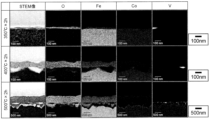
- 1 shows an STEM image and an element mapping image illustrating a cross section of a sample of an example of the present invention.
- 1 shows an STEM image and an element mapping image illustrating a cross section of a sample of a comparative example.
- 1 is a photograph showing the results of a corrosion resistance test for an example of the present invention and a comparative example.
- the Fe-Co alloy substrate of the present invention refers to a strip (coil), rectangular (sheet), or part-shaped thin plate.
- the thickness of the Fe-Co alloy substrate of the present invention can be, for example, 0.5 mm or less. A preferred thickness is 0.25 mm or less.
- the Fe-Co alloy of the present invention refers to an alloy material containing 95% or more Fe + Co by mass, and 25 to 60% Co. The preferred lower limit of the Co content is 40%. This allows for a high magnetic flux density to be achieved.
- the Fe-Co alloy of the present invention may contain V: 1.70-2.10%, Mn: 0.01-0.40%, and one or more of the following elements: Si, Al, Zr, B, Ni, Ta, Nb, W, Ti, Mo, Cr, up to a total of 2.5% by mass.
- Other unavoidably contained impurity elements include C, S, P, and O, and it is preferable to set the upper limit of each to 0.1%.
- the Fe-Co alloy coated substrate of the present invention has an oxide layer on at least one of the front and back surfaces of the Fe-Co alloy substrate having the above-mentioned composition.
- the present invention is characterized in that when the oxide layer is formed on either the front or back surface of the substrate, the thickness of the oxide layer is 280 to 500 nm, and when the oxide layer is formed on both the front and back surfaces of the substrate, the thickness of the oxide layer on the front and back surfaces is within the range of 140 to 500 nm, respectively.
- the oxide layer is formed only on one side of the substrate) or 140 nm (when the oxide layer is formed on both sides (front and back) of the substrate), the oxide layer is not thick enough, and current flows between the laminated single plates in the laminated core, which may cause the iron loss to deteriorate.
- the thickness of the oxide layer is more than 500 nm
- the difference in thermal expansion coefficient between the Fe-Co alloy substrate and the oxide layer becomes large, the adhesion is greatly reduced, and there is a risk that the oxide layer will peel off during core manufacturing.
- the thickness of the oxide layer is more than 500 nm, the magnetic flux density tends to decrease due to the increase in the non-ferromagnetic oxide layer.
- the preferable lower limit of the thickness is different when the oxide layer is formed only on one side (either the front or back) of the substrate and when it is formed on both sides is because it is assumed that the Fe-Co-based alloy coated substrate of the present invention is applied to a laminated core.
- the thickness of the oxide layer between the coated substrates is the sum of the thickness of the oxide layer on the back surface of the substrate and the thickness of the oxide layer on the front surface of the substrate. Therefore, the oxide layer of a coated substrate having an oxide layer on both sides of the substrate can be made thinner than that of a coated substrate having an oxide layer on only one side.
- the preferred lower limit of the oxide layer is 300 nm, and the more preferred lower limit of the oxide layer is 310 nm.
- the preferred lower limit of the oxide layer is 150 nm, the more preferred lower limit of the oxide layer is 160 nm, and the more preferred lower limit of the oxide layer is 180 nm, 200 nm, or 220 nm.
- the preferred upper limit of the oxide layer is 400 nm, and the more preferred upper limit of the oxide layer is 350 nm.
- the lower limit of the oxide layer thickness on the front and back surfaces is 250 nm, respectively.
- the Fe-Co alloy substrate can be coated with a stable oxide layer, and the effect of suppressing rust that may occur during storage of the material can be further improved.
- a more preferable lower limit of the oxide layer thickness is 280 nm, and an even more preferable lower limit of the oxide layer is 300 nm or more.
- the laminated core member obtained by laminating the above-mentioned Fe-Co alloy coated substrate has good magnetic properties.
- the Fe-Co alloy coated substrate of the present invention is also characterized in that the maximum height difference of the unevenness at the interface between the oxide layer and the substrate is 300 nm or less in the cross section in the thickness direction of the substrate. By satisfying this requirement, the Fe-Co alloy coated substrate of the present invention tends to improve the adhesion between the oxide layer and the substrate. If the maximum height difference of the unevenness at the interface between the oxide layer and the substrate exceeds 300 nm, non-uniform stress is generated between the oxide layer and the substrate, and the adhesion of the oxide layer tends to decrease.
- the thickness of the oxide layer and the maximum height difference of the unevenness at the interface between the oxide layer and the substrate in the present invention can be measured, for example, by element mapping using an FE-TEM and the length measurement function of an FE-TEM analysis tool.
- the adhesion in the present invention can be measured, for example, by performing a cross-cut test as specified in JIS K5400 (1990) or JIS K5600.
- an intermediate material having the above-mentioned Fe-Co alloy composition and which has been subjected to a quenching treatment from a temperature above the ordering temperature of about 730°C to be disordered is cold-rolled.
- This intermediate material can be a hot-rolled material or a strip-shaped material obtained by subjecting a hot-rolled material to preliminary cold rolling.
- the oxide layer may be removed, for example, mechanically or chemically.
- the intermediate material in order to obtain a desired plate thickness, is cold-rolled to obtain a cold-rolled material having a plate thickness of 0.5 mm or less, and then magnetic annealing is performed to obtain a sufficiently coarse recrystallized grain structure, thereby obtaining an Fe-Co alloy substrate with good magnetic properties.
- the intermediate material may be processed into a part shape using press punching, wire cutting, laser processing, etc.
- the annealed material that has been subjected to the above-mentioned magnetic annealing is subjected to an oxidation heat treatment so that the thickness is 200 to 500 nm and the maximum height difference of the unevenness at the interface between the oxide layer and the substrate is 300 nm or less in a cross section in the thickness direction.
- the thickness of the oxide layer and the maximum height difference of the unevenness can be mainly controlled by adjusting the heating temperature and heating time of the oxidation heat treatment.
- the oxygen partial pressure may be adjusted to form an oxide layer of the desired thickness. For example, by performing heat treatment in an air atmosphere at 450°C for 0.5 to 4 hours, it is possible to obtain an Fe-Co alloy-coated substrate having an oxide layer as specified in the present invention.
- a cold-rolled material having the Fe-Co alloy composition shown in Table 1 was prepared and subjected to multiple cold rolling processes to obtain a cold-rolled material having a thickness of 0.2 mm. This was then subjected to magnetic annealing in a hydrogen atmosphere at 850°C for 3 hours to obtain an annealed Fe-Co alloy material (Fe-Co alloy substrate). After that, an oxidation heat treatment was performed under the conditions shown in Table 2 to obtain Fe-Co alloy coated substrates of the present invention and comparative examples in which oxide layers were formed on the front and back surfaces of the substrate. For each of the obtained samples, the oxide layer was observed and the adhesion, insulation, and DC magnetic properties were evaluated.
- the surface of the sample was protected with a C film, and a film-like cross-sectional test piece was processed from the outermost surface of the test piece parallel to the width direction using an FIB-SEM, and STEM observation was performed using an FE-TEM.
- elemental mapping of O, Fe, Co, and V was also performed.
- the results are shown in Figure 1.
- the bottom side of the image is the Fe-Co alloy substrate side.
- the thickness of the oxide layer and the maximum height difference of the unevenness at the interface between the oxide layer and the substrate were measured using the length measurement function of the FE-TEM analysis tool.
- the adhesion was evaluated by conducting a cross-cut test specified in JIS K5400 (1990) to check whether the insulating layer had peeled off.
- the insulation was evaluated by measuring the sheet resistance (surface resistivity) of the surface using the four-probe method with a resistivity meter.
- the measurement results of the thickness of the oxide layer, the maximum height difference of the unevenness at the interface between the oxide layer and the substrate, the presence or absence of film peeling, and the sheet resistance are shown in Table 3.
- the "maximum height difference between the projections and recesses" in Table 3 refers to the maximum height difference between the projections and recesses at the interface between the oxide layer and the substrate.
- the measurement results in Table 3 are all for the oxide layer on the surface side of the substrate. In the actual sample, an oxide layer was also formed on the back side of the substrate, and its thickness and maximum height difference between the projections and recesses were about the same as those on the surface side.
- the DC magnetic properties were measured on samples that were made by cutting 0.2 mm thick cold-rolled material to a length of 110 mm in the rolling direction and 25 mm perpendicular to the rolling direction, and then magnetically annealing the material in a hydrogen atmosphere at 850°C for 3 hours.
- the same samples were then subjected to oxidation heat treatment under the conditions shown in Table 2, after which DC magnetic measurements were performed again to measure the rate of change in coercivity, maximum permeability, and magnetic flux density before and after oxidation heat treatment.
- Table 4 The results are shown in Table 4.
- the thickness and form (maximum step difference of unevenness) of the oxide layer differ depending on the heating temperature and heating time of the oxidation heat treatment.
- Samples 1 to 3 and 11 to 12 in which the maximum height difference of unevenness at the interface between the oxide layer and the substrate is 300 nm or less, had good adhesion and no film peeling.
- Sample 13 in which the maximum height difference of unevenness at the interface between the oxide layer and the substrate is more than 300 nm, had poor adhesion and film peeling occurred. If the adhesion of the oxide layer is poor, the insulating layer may peel off during the production of the laminated core, causing current to flow between the laminated veneers, which may worsen iron loss, which is not preferable.
- samples No. 2, 3, and 13 showed excellent values, and it was found that they exhibited good insulation.
- Sample No. 1 had a smaller sheet resistance than No. 2 and No. 3, but when actually used as a laminated core, oxide layers are formed on both surfaces of the substrate, so the film thickness is the sum of the film thickness on the front side and the film thickness on the back side of the substrate. Therefore, the oxide layer thickness of No. 1 is about twice as thick (about 490 nm) when used as a laminated core, so it can be seen that it exhibits sufficient insulation.
- the oxide layer of No. 11 and No. 12, which are comparative examples is too thin, so even if the thickness is doubled assuming lamination, it does not reach the oxide layer thickness of No.
- the Fe-Co-based alloy coated substrate of the present invention has better insulation, adhesion, and magnetic properties than the Fe-Co-based alloy coated substrate of the comparative example, and in particular, the No. 2 of the present invention, which has an oxide layer thickness of 250 nm or more, has better insulation, adhesion, and magnetic properties than the Fe-Co-based alloy coated substrate of the comparative example. It was confirmed that No. 2 and No. 3 also had excellent rust resistance.
Landscapes
- Chemical & Material Sciences (AREA)
- Engineering & Computer Science (AREA)
- Materials Engineering (AREA)
- Mechanical Engineering (AREA)
- Metallurgy (AREA)
- Organic Chemistry (AREA)
- Power Engineering (AREA)
- Physics & Mathematics (AREA)
- Chemical Kinetics & Catalysis (AREA)
- Electromagnetism (AREA)
- Dispersion Chemistry (AREA)
- Manufacturing & Machinery (AREA)
- Thermal Sciences (AREA)
- Crystallography & Structural Chemistry (AREA)
- Soft Magnetic Materials (AREA)
Priority Applications (3)
| Application Number | Priority Date | Filing Date | Title |
|---|---|---|---|
| CN202480019057.8A CN120883291A (zh) | 2023-03-23 | 2024-02-02 | Fe-Co系合金被覆基材及层叠芯构件 |
| EP24774468.3A EP4685263A1 (en) | 2023-03-23 | 2024-02-02 | Fe-co based alloy coated substrate and laminated core member |
| JP2025508188A JP7715312B2 (ja) | 2023-03-23 | 2024-02-02 | Fe-Co系合金被覆基材および積層コア部材 |
Applications Claiming Priority (2)
| Application Number | Priority Date | Filing Date | Title |
|---|---|---|---|
| JP2023046520 | 2023-03-23 | ||
| JP2023-046520 | 2023-03-23 |
Publications (1)
| Publication Number | Publication Date |
|---|---|
| WO2024195322A1 true WO2024195322A1 (ja) | 2024-09-26 |
Family
ID=92841313
Family Applications (1)
| Application Number | Title | Priority Date | Filing Date |
|---|---|---|---|
| PCT/JP2024/003598 Ceased WO2024195322A1 (ja) | 2023-03-23 | 2024-02-02 | Fe-Co系合金被覆基材および積層コア部材 |
Country Status (4)
| Country | Link |
|---|---|
| EP (1) | EP4685263A1 (https=) |
| JP (1) | JP7715312B2 (https=) |
| CN (1) | CN120883291A (https=) |
| WO (1) | WO2024195322A1 (https=) |
Citations (9)
| Publication number | Priority date | Publication date | Assignee | Title |
|---|---|---|---|---|
| JPS56112498A (en) * | 1980-02-05 | 1981-09-04 | Tdk Corp | Formation of insulation coating layer of magnetic metal sheet |
| JPS61295357A (ja) * | 1985-06-20 | 1986-12-26 | エヌ・ベ−・フイリツプス・フル−イランペンフアブリケン | 二酸化ケイ素の絶縁被膜を有する強磁性のアモルフアス金属テ−プの製造方法 |
| JPH0813153A (ja) * | 1994-06-30 | 1996-01-16 | Korea Advanced Inst Of Sci Technol | 非晶質磁性合金薄帯の絶縁被膜形成方法 |
| US20030019096A1 (en) * | 2001-06-26 | 2003-01-30 | Weihs Timothy P. | Magnetic devices comprising magnetic meta-materials |
| JP2006336061A (ja) * | 2005-06-01 | 2006-12-14 | Hitachi Metals Ltd | 軟磁性部材 |
| JP2012521649A (ja) | 2009-03-26 | 2012-09-13 | ヴァキュームシュメルツェ ゲーエムベーハー ウント コンパニー カーゲー | 軟磁性材料による積層コア,及び軟磁性の積層コアを形成する接着力によりコア単層板を接合する方法 |
| JP2018529021A (ja) * | 2015-07-29 | 2018-10-04 | アペラム | FeCo合金、FeSi合金またはFeシートもしくはストリップおよびその製造方法、前記シートまたはストリップから製造された磁気変圧器コア、ならびにそれを備える変圧器 |
| JP2020202314A (ja) * | 2019-06-11 | 2020-12-17 | 鈴木 茂 | 積層鉄心用板材の製造方法、積層鉄心用板材および積層鉄心 |
| JP2022512498A (ja) * | 2018-12-13 | 2022-02-04 | ポスコ | 方向性電磁鋼板およびその製造方法 |
Family Cites Families (2)
| Publication number | Priority date | Publication date | Assignee | Title |
|---|---|---|---|---|
| JP5085595B2 (ja) * | 2008-09-08 | 2012-11-28 | 株式会社東芝 | コアシェル型磁性材料、コアシェル型磁性材料の製造方法、デバイス装置、およびアンテナ装置。 |
| US20160307679A1 (en) * | 2013-12-26 | 2016-10-20 | Drexel University | Soft Magnetic Composites for Electric Motors |
-
2024
- 2024-02-02 EP EP24774468.3A patent/EP4685263A1/en active Pending
- 2024-02-02 WO PCT/JP2024/003598 patent/WO2024195322A1/ja not_active Ceased
- 2024-02-02 JP JP2025508188A patent/JP7715312B2/ja active Active
- 2024-02-02 CN CN202480019057.8A patent/CN120883291A/zh active Pending
Patent Citations (9)
| Publication number | Priority date | Publication date | Assignee | Title |
|---|---|---|---|---|
| JPS56112498A (en) * | 1980-02-05 | 1981-09-04 | Tdk Corp | Formation of insulation coating layer of magnetic metal sheet |
| JPS61295357A (ja) * | 1985-06-20 | 1986-12-26 | エヌ・ベ−・フイリツプス・フル−イランペンフアブリケン | 二酸化ケイ素の絶縁被膜を有する強磁性のアモルフアス金属テ−プの製造方法 |
| JPH0813153A (ja) * | 1994-06-30 | 1996-01-16 | Korea Advanced Inst Of Sci Technol | 非晶質磁性合金薄帯の絶縁被膜形成方法 |
| US20030019096A1 (en) * | 2001-06-26 | 2003-01-30 | Weihs Timothy P. | Magnetic devices comprising magnetic meta-materials |
| JP2006336061A (ja) * | 2005-06-01 | 2006-12-14 | Hitachi Metals Ltd | 軟磁性部材 |
| JP2012521649A (ja) | 2009-03-26 | 2012-09-13 | ヴァキュームシュメルツェ ゲーエムベーハー ウント コンパニー カーゲー | 軟磁性材料による積層コア,及び軟磁性の積層コアを形成する接着力によりコア単層板を接合する方法 |
| JP2018529021A (ja) * | 2015-07-29 | 2018-10-04 | アペラム | FeCo合金、FeSi合金またはFeシートもしくはストリップおよびその製造方法、前記シートまたはストリップから製造された磁気変圧器コア、ならびにそれを備える変圧器 |
| JP2022512498A (ja) * | 2018-12-13 | 2022-02-04 | ポスコ | 方向性電磁鋼板およびその製造方法 |
| JP2020202314A (ja) * | 2019-06-11 | 2020-12-17 | 鈴木 茂 | 積層鉄心用板材の製造方法、積層鉄心用板材および積層鉄心 |
Non-Patent Citations (1)
| Title |
|---|
| See also references of EP4685263A1 |
Also Published As
| Publication number | Publication date |
|---|---|
| CN120883291A (zh) | 2025-10-31 |
| EP4685263A4 (en) | 2026-01-28 |
| JPWO2024195322A1 (https=) | 2024-09-26 |
| JP7715312B2 (ja) | 2025-07-30 |
| EP4685263A1 (en) | 2026-01-28 |
Similar Documents
| Publication | Publication Date | Title |
|---|---|---|
| JP5073853B2 (ja) | 無方向性電磁鋼板及びその製造方法 | |
| CN101821418B (zh) | 高频铁损低的无方向性电磁钢板及其制造方法 | |
| JP2023507594A (ja) | 無方向性電磁鋼板およびその製造方法 | |
| RU2485186C1 (ru) | Неориентированная магнитная листовая сталь и способ ее изготовления | |
| JP7318635B2 (ja) | 磁性コアとその製造方法、およびコイル部品 | |
| JP4635112B2 (ja) | 無方向性電磁鋼板及びその製造方法 | |
| WO2004059022A1 (ja) | Fe-Cr-Si系無方向性電磁鋼板およびその製造方法 | |
| JP7715312B2 (ja) | Fe-Co系合金被覆基材および積層コア部材 | |
| KR102230629B1 (ko) | 방향성 전기 강판 및 방향성 전기 강판의 제조 방법 | |
| JP7271064B2 (ja) | 積層鉄心用板材の製造方法、積層鉄心用板材および積層鉄心 | |
| JPH0888114A (ja) | 無方向性電磁鋼板の製造方法 | |
| JP2025111578A (ja) | 被覆部材 | |
| EP3842555B1 (en) | Soft magnetic alloy and magnetic core | |
| JP6464750B2 (ja) | 複数の結晶配向層を有する軟磁性Fe系金属板及びその製造方法 | |
| JPH08203718A (ja) | 絶縁皮膜を有する軟質磁性材料及びその製造方法 | |
| JP4306445B2 (ja) | 高周波磁気特性に優れたFe−Cr−Si系無方向性電磁鋼板およびその製造方法 | |
| WO2024185627A1 (ja) | Fe-Co系合金基材およびその製造方法、Fe-Co系合金被覆基材およびその製造方法、ならびに積層コア部材 | |
| JP2024030809A (ja) | 軟磁性鋼板 | |
| JP3512109B2 (ja) | プレス加工用複合磁性薄帯およびその製造方法、ならびにそれを用いた電磁シールド部材 | |
| JP4258163B2 (ja) | 歪取焼鈍後の磁気特性に優れた無方向性電磁鋼板 | |
| JP7695636B2 (ja) | Fe-Co系被覆合金基材の製造方法、Fe-Co系被覆合金基材および積層コア部材 | |
| JP2001262289A (ja) | 1kHz以上の周波域における磁気特性に優れる無方向性電磁鋼板 | |
| JP2001295001A (ja) | 高周波磁気特性および溶接性に優れる無方向性電磁鋼板 | |
| JPWO2019132039A1 (ja) | クラッド鋼板 | |
| JP6464753B2 (ja) | 複数の結晶配向層を有する軟磁性Fe系金属板及びその製造方法 |
Legal Events
| Date | Code | Title | Description |
|---|---|---|---|
| 121 | Ep: the epo has been informed by wipo that ep was designated in this application |
Ref document number: 24774468 Country of ref document: EP Kind code of ref document: A1 |
|
| WWE | Wipo information: entry into national phase |
Ref document number: 2025508188 Country of ref document: JP |
|
| WWE | Wipo information: entry into national phase |
Ref document number: 202480019057.8 Country of ref document: CN |
|
| WWE | Wipo information: entry into national phase |
Ref document number: 2024774468 Country of ref document: EP |
|
| NENP | Non-entry into the national phase |
Ref country code: DE |
|
| WWP | Wipo information: published in national office |
Ref document number: 202480019057.8 Country of ref document: CN |
|
| ENP | Entry into the national phase |
Ref document number: 2024774468 Country of ref document: EP Effective date: 20251023 |
|
| ENP | Entry into the national phase |
Ref document number: 2024774468 Country of ref document: EP Effective date: 20251023 |
|
| ENP | Entry into the national phase |
Ref document number: 2024774468 Country of ref document: EP Effective date: 20251023 |
|
| ENP | Entry into the national phase |
Ref document number: 2024774468 Country of ref document: EP Effective date: 20251023 |
|
| ENP | Entry into the national phase |
Ref document number: 2024774468 Country of ref document: EP Effective date: 20251023 |
|
| ENP | Entry into the national phase |
Ref document number: 2024774468 Country of ref document: EP Effective date: 20251023 |