WO2024189738A1 - 可撓性ケーブルを有するエンコーダ - Google Patents
可撓性ケーブルを有するエンコーダ Download PDFInfo
- Publication number
- WO2024189738A1 WO2024189738A1 PCT/JP2023/009639 JP2023009639W WO2024189738A1 WO 2024189738 A1 WO2024189738 A1 WO 2024189738A1 JP 2023009639 W JP2023009639 W JP 2023009639W WO 2024189738 A1 WO2024189738 A1 WO 2024189738A1
- Authority
- WO
- WIPO (PCT)
- Prior art keywords
- encoder
- electronic component
- protrusion
- cover
- flexible cable
- Prior art date
- Legal status (The legal status is an assumption and is not a legal conclusion. Google has not performed a legal analysis and makes no representation as to the accuracy of the status listed.)
- Ceased
Links
Images


Classifications
-
- G—PHYSICS
- G01—MEASURING; TESTING
- G01D—MEASURING NOT SPECIALLY ADAPTED FOR A SPECIFIC VARIABLE; ARRANGEMENTS FOR MEASURING TWO OR MORE VARIABLES NOT COVERED IN A SINGLE OTHER SUBCLASS; TARIFF METERING APPARATUS; MEASURING OR TESTING NOT OTHERWISE PROVIDED FOR
- G01D5/00—Mechanical means for transferring the output of a sensing member; Means for converting the output of a sensing member to another variable where the form or nature of the sensing member does not constrain the means for converting; Transducers not specially adapted for a specific variable
- G01D5/12—Mechanical means for transferring the output of a sensing member; Means for converting the output of a sensing member to another variable where the form or nature of the sensing member does not constrain the means for converting; Transducers not specially adapted for a specific variable using electric or magnetic means
- G01D5/244—Mechanical means for transferring the output of a sensing member; Means for converting the output of a sensing member to another variable where the form or nature of the sensing member does not constrain the means for converting; Transducers not specially adapted for a specific variable using electric or magnetic means influencing characteristics of pulses or pulse trains; generating pulses or pulse trains
- G01D5/245—Mechanical means for transferring the output of a sensing member; Means for converting the output of a sensing member to another variable where the form or nature of the sensing member does not constrain the means for converting; Transducers not specially adapted for a specific variable using electric or magnetic means influencing characteristics of pulses or pulse trains; generating pulses or pulse trains using a variable number of pulses in a train
Definitions
- This disclosure relates to an encoder having a flexible cable.
- encoders such as optical encoders attached to the motors that drive each axis are known.
- One well-known example is an optical encoder that has a housing formed of a main body and a cover, and has a flexible cable (FPC cable) arranged inside the housing (see, for example, Patent Document 1).
- a magnetic rotary encoder having a housing formed of a main body and a cover and an FPC cable disposed inside the housing is also well known (see, for example, Patent Document 2).
- an encoder comprising a printed circuit board having electronic components, a flexible cable connected to a connector mounted on the printed circuit board, and a cover configured to cover the printed circuit board and the flexible cable, the cover having a protrusion capable of contacting the flexible cable, and the protrusion configured to bend the flexible cable so that the minimum distance of the flexible cable relative to the electronic components is equal to or greater than an allowable distance determined based on the function of the encoder.
- FIG. 1 is a schematic cross-sectional side view of an encoder according to a first embodiment.
- FIG. 2 is a schematic perspective view of a cover of the encoder of FIG. 1 .
- 1 is a schematic cross-sectional side view of an encoder according to a comparative example.
- FIG. 11 is a schematic cross-sectional side view of an encoder according to a second embodiment.
- FIG. 11 is a schematic plan view of an encoder according to a third embodiment.
- (First embodiment) 1 is a schematic cross-sectional side view of an encoder 10 according to a first embodiment of the present disclosure.
- the encoder 10 is, for example, an optical encoder attached to a motor such as a servo motor that drives each axis of a robot, and detects the rotational angle position of a rotating shaft 12 of the motor.
- the encoder 10 has a slit plate 14 formed with a plurality of slits (not shown) and configured to rotate integrally with the rotating shaft 12, and a light-emitting unit 16 such as an LED and a light-receiving unit 18 such as a photosensor that are arranged opposite each other with the slit plate 14 in between.
- the light-emitting unit 16 is disposed on a mounting plate 20 for mounting the encoder 10 to a predetermined location on a motor or the like.
- the light-receiving unit 18 is disposed on a first surface (e.g., the downward surface) of a printed circuit board (PCB) 22 disposed opposite the mounting plate 20, and generates a signal based on the light from the light-emitting unit 16 received through the slit plate 14.
- An electronic component 24 such as an LSI is mounted on a second surface (e.g., the upward surface) of the printed circuit board 22.
- the electronic component 24 can also include integrated circuits and electronic circuits that perform arithmetic processing, such as microcomputers and DSPs (digital signal processors).
- the electronic component 24 generates information (data) about the rotational position of the rotating shaft 12 based on the signal generated by the light receiving unit 18.
- the data generated by the electronic component 24 is output to the outside via a flexible cable (FPC cable in the illustrated example) 28 connected to a connector 26 mounted on the PCB 22.
- the encoder 10 has a cover 30 configured to cover the PCB 22 and the FPC cable 28 in order to protect the electronic components 24 mounted on the PCB 22 from the outside.
- the FPC cable 28 is connected by soldering or the like to a connection part 36 disposed in an opening 34 formed on the side of the cover 30, and the connection part 36 is connected to an external device (not shown) that processes the output data of the encoder 10 by a cable or the like (not shown).
- the inner surface of the cover 30 is provided with a protrusion 32 that can come into contact with the FPC cable 28, and the protrusion 32 is configured to come into contact with and bend the flexible cable 28 so that the minimum distance of the FPC cable 28 to the electronic component 24 is equal to or greater than the allowable distance determined based on the noise tolerance and other functions of the encoder 10. This allowable distance will be described later.
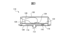
- FIG. 3 shows an example of the configuration of an encoder in which the cover does not have a protrusion. Note that components that may be the same as those in the first embodiment are given reference numbers that are 100 larger than the reference numbers in the first embodiment, and detailed descriptions are omitted.
- the FPC cable 128 is considerably longer than the distance between the components (here, the electronic component 124 and the connector 126) that are connected by the FPC cable 128. Since the FPC cable 128 is flexible, it may come into contact with the electronic component 124.
- a protrusion 32 that can come into contact with the FPC cable 28 is provided on the inner surface of the cover 30, and the degree of bending of the FPC cable 28 is controlled so that the FPC cable 28 does not come into contact with the electronic component 24 or approach within an allowable distance, thereby reliably preventing a decrease in noise tolerance caused by the FPC cable 28 and an excessive temperature rise in the electronic component 24.
- the FPC cable 28 is not in contact with the electronic component 24, but is close enough to cause a substantial decrease in the noise resistance of the encoder.
- the FPC cable 28 is maintained by the protrusion 32 at a distance from the electronic component that is greater than the allowable distance at which the noise resistance is not decreased.
- the allowable distance in this embodiment means, for example, the minimum distance between the FPC cable 28 and the electronic component 24 at which the noise resistance is not decreased, and can be empirically determined based on the noise resistance required for the encoder.
- the allowable distance can be determined based on the amount of temperature rise in the electronic component 24 that may affect the function of the encoder, and more specifically, the allowable distance can be empirically determined so that the amount of temperature rise in the electronic component 24 due to contact or proximity with the FPC cable 28 is equal to or less than the maximum value at which the function of the encoder is not impaired.
- the allowable distance can be various values depending on the size and structure of the encoder, and is, for example, 1 mm, 2 mm, 3 mm, 4 mm, or 5 mm.
- the position, size and shape of the protrusion 32 can be appropriately determined based on the arrangement and shape of the electronic component 24.
- the protrusion 32 is arranged above, and preferably directly above, the electronic component 24 in a direction perpendicular to the surface of the PCB 22, and in a plan view (when viewed in a direction perpendicular to the surface of the PCB 22) (see Figure 5 described below), the electronic component 24 has a substantially rectangular shape, while the protrusion 32 has a shape (here, substantially circular) that encompasses the electronic component 24.
- the tip of the protrusion 32 may have substantially the same shape as the electronic component 24 in a plan view.
- the distance between the tip of the protrusion 32 (the lower end in Figure 1) and the electronic component 24 is preferably short enough that the bent FPC cable 28 cannot be interposed between the tip and the electronic component 24, and is, for example, 1 to 5 mm.
- protrusions 32 are arranged and shaped in such a way that no matter how the FPC cable 28 is deformed or bent, the FPC cable 28 is prevented from contacting or coming into close proximity with the electronic components 24, preventing a decrease in noise resistance, etc.
- the material that constitutes the cover 30 and the protrusions 32 there are no particular restrictions on the material that constitutes the cover 30 and the protrusions 32; for example, resin or metal can be used.
- the protrusions 32 may be attached to the cover 30 by adhesive or other means after being molded into a predetermined shape, or may be molded integrally with the cover 30. With regard to the latter, for example, molding the cover 30 and the protrusions 32 integrally with resin is advantageous in terms of cost.
- Second Example 4 is a schematic side cross-sectional view of an encoder 10a according to the second embodiment.
- the second embodiment only the parts different from the first embodiment will be described, and the components of the second embodiment that may be similar to those of the first embodiment will be given the same reference numerals as those of the first embodiment, and detailed descriptions thereof will be omitted.
- the protrusion 32 and the electronic component 24 overlap in a plan view (more specifically, the protrusion 32 encompasses the electronic component 24), whereas in the second embodiment, the protrusion 32a provided on the inner surface of the cover 30a is disposed between the electronic component 24 and the connector 26.
- the FPC cable 28 can be intentionally entangled with the protrusion 32a, thereby ensuring that the minimum distance of the FPC cable 28 from the electronic component 24 is equal to or greater than the allowable distance determined based on the noise tolerance of the encoder 10a. Therefore, in the second embodiment, a decrease in the noise tolerance of the encoder 10a is also prevented.
- the position, size, and shape of the protrusion 32a can be appropriately selected so that the FPC cable 28 can be suitably entangled.
- (Third Example) 5 is a schematic plan view of an encoder 10b according to the third embodiment.
- the third embodiment only the parts different from the first embodiment will be described, and the components of the third embodiment that may be similar to those of the first embodiment will be given the same reference numerals as those of the first embodiment, and detailed descriptions thereof will be omitted.
- the third embodiment has multiple (two in the illustrated example) protrusions 32, 32b.
- the third embodiment is advantageous, for example, when there are multiple electronic components with which the FPC cable 28 should not come into contact or be close to, from the standpoint of noise immunity.
- two electronic components 24, 24b are arranged at a certain distance apart as in the illustrated example, by providing the cover 30b with protrusions 32, 32b that respectively encompass the electronic components 24, 24b in a plan view, it becomes possible to suitably bend the FPC cable 28 so that it does not come into contact with or be close to the electronic components, regardless of the number of electronic components.
- each protrusion 32a can be selected as appropriate, but for example, if the surface is curved, such as with cylindrical protrusions 32, there is an effect of suppressing damage to the FPC cable 28 due to contact with the protrusions 32.
- the manufacturing process for the encoder in the above embodiments can be appropriately selected and determined based on the position and shape of the protrusions.
- the cover 30 when attaching the cover 30, instead of moving it vertically from above the PCB 22 in the direction of its surface, it is attached by sliding it from the right side to the left side, which allows the FPC cable 28 to bend appropriately as shown in FIG. 1.
- an optical rotary encoder has been described, but the present disclosure is not limited to this.
- the present disclosure can also be applied to magnetic encoders and linear encoders that have a configuration in which the FPC cable can abut or come into close proximity to an electronic component.
- the FPC cable can be bent so that it does not come into contact with electronic components or come within an allowable distance by using a simple means such as a cover with protrusions, and this makes it possible to prevent a decrease in the noise tolerance of the encoder. This makes it possible to provide a highly reliable encoder at low cost.
- An encoder comprising: a printed circuit board having electronic components; a flexible cable connected to a connector mounted on the printed circuit board; and a cover configured to cover the printed circuit board and the flexible cable, wherein the cover has a protrusion capable of contacting the flexible cable, and the protrusion is configured to bend the flexible cable so that a minimum distance of the flexible cable from the electronic components is equal to or greater than an allowable distance determined based on the function of the encoder.
- Appendix 7 The encoder according to any one of appendixes 1 to 5, wherein the allowable distance is determined based on an amount of temperature rise of the electronic components that may affect the function of the encoder.
Landscapes
- Physics & Mathematics (AREA)
- General Physics & Mathematics (AREA)
- Transmission And Conversion Of Sensor Element Output (AREA)
- Optical Transform (AREA)
Priority Applications (2)
| Application Number | Priority Date | Filing Date | Title |
|---|---|---|---|
| JP2025506289A JPWO2024189738A1 (https=) | 2023-03-13 | 2023-03-13 | |
| PCT/JP2023/009639 WO2024189738A1 (ja) | 2023-03-13 | 2023-03-13 | 可撓性ケーブルを有するエンコーダ |
Applications Claiming Priority (1)
| Application Number | Priority Date | Filing Date | Title |
|---|---|---|---|
| PCT/JP2023/009639 WO2024189738A1 (ja) | 2023-03-13 | 2023-03-13 | 可撓性ケーブルを有するエンコーダ |
Publications (1)
| Publication Number | Publication Date |
|---|---|
| WO2024189738A1 true WO2024189738A1 (ja) | 2024-09-19 |
Family
ID=92754683
Family Applications (1)
| Application Number | Title | Priority Date | Filing Date |
|---|---|---|---|
| PCT/JP2023/009639 Ceased WO2024189738A1 (ja) | 2023-03-13 | 2023-03-13 | 可撓性ケーブルを有するエンコーダ |
Country Status (2)
| Country | Link |
|---|---|
| JP (1) | JPWO2024189738A1 (https=) |
| WO (1) | WO2024189738A1 (https=) |
Citations (4)
| Publication number | Priority date | Publication date | Assignee | Title |
|---|---|---|---|---|
| JP2008182609A (ja) * | 2007-01-25 | 2008-08-07 | Kyocera Corp | 電子機器 |
| WO2011111345A1 (ja) * | 2010-03-09 | 2011-09-15 | コニカミノルタオプト株式会社 | レンズ鏡筒 |
| JP2015174207A (ja) * | 2014-03-18 | 2015-10-05 | セイコーエプソン株式会社 | ロボット |
| JP2021069217A (ja) * | 2019-10-25 | 2021-04-30 | 三菱電機株式会社 | インバータ装置 |
Family Cites Families (11)
| Publication number | Priority date | Publication date | Assignee | Title |
|---|---|---|---|---|
| JPH0423179U (https=) * | 1990-06-14 | 1992-02-26 | ||
| JPH0677428U (ja) * | 1993-04-08 | 1994-10-28 | 山武ハネウエル株式会社 | ケース内のケーブルクランプ構造 |
| JPH077279A (ja) * | 1993-06-18 | 1995-01-10 | Tec Corp | 電気機器 |
| JP2003283177A (ja) * | 2002-03-27 | 2003-10-03 | Yaskawa Electric Corp | 電子装置の放射ノイズ低減装置 |
| JP4712461B2 (ja) * | 2005-07-11 | 2011-06-29 | 矢崎総業株式会社 | 表示パネル用接続ケーブルの保護構造及び車両用計器の組付方法 |
| JP4721226B2 (ja) * | 2006-04-27 | 2011-07-13 | 京セラ株式会社 | 電子機器 |
| JP6948872B2 (ja) * | 2017-07-31 | 2021-10-13 | 日本電産サンキョー株式会社 | モータ |
| JP7131439B2 (ja) * | 2019-03-07 | 2022-09-06 | 株式会社オートネットワーク技術研究所 | 外装部材及びワイヤハーネス |
| JP7363537B2 (ja) * | 2020-01-31 | 2023-10-18 | 株式会社デンソー | 車両用表示装置 |
| JP2022011580A (ja) * | 2020-06-30 | 2022-01-17 | パナソニックIpマネジメント株式会社 | 電気機器 |
| TWI905260B (zh) * | 2020-11-12 | 2025-11-21 | 日商發那科股份有限公司 | 分隔板及線條構件的保護構件 |
-
2023
- 2023-03-13 WO PCT/JP2023/009639 patent/WO2024189738A1/ja not_active Ceased
- 2023-03-13 JP JP2025506289A patent/JPWO2024189738A1/ja active Pending
Patent Citations (4)
| Publication number | Priority date | Publication date | Assignee | Title |
|---|---|---|---|---|
| JP2008182609A (ja) * | 2007-01-25 | 2008-08-07 | Kyocera Corp | 電子機器 |
| WO2011111345A1 (ja) * | 2010-03-09 | 2011-09-15 | コニカミノルタオプト株式会社 | レンズ鏡筒 |
| JP2015174207A (ja) * | 2014-03-18 | 2015-10-05 | セイコーエプソン株式会社 | ロボット |
| JP2021069217A (ja) * | 2019-10-25 | 2021-04-30 | 三菱電機株式会社 | インバータ装置 |
Also Published As
| Publication number | Publication date |
|---|---|
| JPWO2024189738A1 (https=) | 2024-09-19 |
Similar Documents
| Publication | Publication Date | Title |
|---|---|---|
| JP4085079B2 (ja) | 回転検出センサ | |
| KR970029418A (ko) | 디스크 장치의 캐리지 구조 | |
| JP5006177B2 (ja) | エンコーダー、張力緩和器具を備えたエンコーダーの蓋及びそれらを備えたエンコーダーシステム | |
| WO2013098935A1 (ja) | エンコーダ及びサーボモータ | |
| EP1732182B1 (en) | Connecting structure of rotary connector and steering angle sensor | |
| JP7462030B2 (ja) | 回転角度測定装置、回転角度測定システム、および電動モータ | |
| WO2024189738A1 (ja) | 可撓性ケーブルを有するエンコーダ | |
| CN114424408B (zh) | 电子器件及电子设备 | |
| CN204514335U (zh) | 检测器 | |
| JP2011003623A (ja) | プリント基板の実装構造 | |
| JP2021158845A (ja) | 制御装置 | |
| JP6479297B1 (ja) | エンコーダの組み立て方法、エンコーダ及びサーボモータ | |
| US11702037B2 (en) | Motor device | |
| JP5790087B2 (ja) | モータおよびディスク駆動装置 | |
| JP7651069B2 (ja) | 回路接続装置、及び回転電機装置 | |
| JP7828818B2 (ja) | ロータリエンコーダおよびトレランスリングを有するアセンブリ | |
| TW202543351A (zh) | 殼體及電子設備 | |
| JP4432027B2 (ja) | 移動物体検出装置 | |
| JP3765541B2 (ja) | 光ピックアップ装置 | |
| JP2023077825A (ja) | 引き出し構造 | |
| JP2007115794A (ja) | フレキシブルプリント基板並びにフレキシブルプリント基板を用いた磁気式エンコーダ及びサーボモータ | |
| JP2015126028A (ja) | 電子装置 | |
| JPWO2013098935A1 (ja) | エンコーダ及びサーボモータ | |
| JP2002243504A (ja) | フォトインタラプタの固定構造 | |
| JPH04116728U (ja) | パルスエンコーダ |
Legal Events
| Date | Code | Title | Description |
|---|---|---|---|
| 121 | Ep: the epo has been informed by wipo that ep was designated in this application |
Ref document number: 23927360 Country of ref document: EP Kind code of ref document: A1 |
|
| WWE | Wipo information: entry into national phase |
Ref document number: 2025506289 Country of ref document: JP |
|
| NENP | Non-entry into the national phase |
Ref country code: DE |
|
| 122 | Ep: pct application non-entry in european phase |
Ref document number: 23927360 Country of ref document: EP Kind code of ref document: A1 |