WO2024161627A1 - 送風機 - Google Patents
送風機 Download PDFInfo
- Publication number
- WO2024161627A1 WO2024161627A1 PCT/JP2023/003557 JP2023003557W WO2024161627A1 WO 2024161627 A1 WO2024161627 A1 WO 2024161627A1 JP 2023003557 W JP2023003557 W JP 2023003557W WO 2024161627 A1 WO2024161627 A1 WO 2024161627A1
- Authority
- WO
- WIPO (PCT)
- Prior art keywords
- wall
- casing
- axial direction
- blower
- outer circumferential
- Prior art date
- Legal status (The legal status is an assumption and is not a legal conclusion. Google has not performed a legal analysis and makes no representation as to the accuracy of the status listed.)
- Ceased
Links
Images










Classifications
-
- F—MECHANICAL ENGINEERING; LIGHTING; HEATING; WEAPONS; BLASTING
- F04—POSITIVE - DISPLACEMENT MACHINES FOR LIQUIDS; PUMPS FOR LIQUIDS OR ELASTIC FLUIDS
- F04D—NON-POSITIVE-DISPLACEMENT PUMPS
- F04D29/00—Details, component parts, or accessories
- F04D29/40—Casings; Connections of working fluid
- F04D29/42—Casings; Connections of working fluid for radial or helico-centrifugal pumps
- F04D29/44—Fluid-guiding means, e.g. diffusers
Definitions
- This disclosure relates to a blower.
- a blower is composed of an impeller that is rotated by a drive motor, and a casing inside which the impeller is rotatably arranged.
- the impeller creates an air flow as it rotates, and the air around the blower is sucked in through the casing's intake port and blown out through the casing's outlet port.
- the casing determines the direction of the air flow, and has the function of straightening the air flow.
- the blower When the frequency of the electromagnetic vibrations generated by the motor that drives the impeller, which acts as a vibration source, matches the natural frequency of the casing, the blower will resonate. The vibrations will also propagate through the casing and radiate sound inside the casing, exciting acoustic resonance. These can increase the noise of the blower. Furthermore, when part of the air flow blown out as the impeller rotates collides with the inner surface of the casing, the flow fluctuations cause vibrations, which can increase the noise of the blower.
- Patent Document 1 proposes a technique for adjusting the natural frequency by providing a reinforcing rib protruding from the fan duct as the casing and filling the inside of the reinforcing rib with a filler to increase the mass.
- Patent Document 2 proposes that the fan shroud as the casing has a double-tube structure to increase the rigidity of the fan shroud and suppress vibration.
- Patent Document 2 also proposes a technique in which a resonator is formed by the inner and outer tubes of the double-tube structure, and sound is silenced by resonance with the resonator.
- Patent Document 1 Although it is possible to change the natural frequency by modifying the shape of the fan duct, the fan duct is a cylindrical surface, and vibrations propagate throughout the entire fan duct and radiate sound into the internal space of the fan duct, making it easy for acoustic resonance to occur.
- Patent Document 2 noise reduction is achieved by using a resonator to reduce the resonance sound generated within the fan shroud.
- the fan shroud has a double-tube structure in which the inner tube is the same width as the outer tube, the resonance sound generated within the fan shroud diffuses throughout the entire cylindrical inner tube, and therefore this is not a sufficient measure to reduce noise. Therefore, the present disclosure has an object to provide a blower that can suppress noise.
- the blower according to the present disclosure comprises an impeller having multiple blades and attached to the rotating shaft of a drive motor, a casing having an intake port for drawing in surrounding air and an outlet port for blowing out air and to which the drive motor is attached so as to rotate the impeller, and an inner wall disposed radially outward from the impeller and provided on the casing so as to face the inner surface of the casing.
- the inner wall is configured so that a portion of the inner wall at the extreme end in one axial direction is located on the side opposite to the one axial direction relative to a portion of the inner surface of the casing at the extreme end in the one axial direction.
- the inner wall is configured so that the portion of the inner wall at the extreme end in one axial direction is located on the opposite side of the portion of the inner surface of the casing at the extreme end in one axial direction. Since acoustic resonance in the internal space of the casing is suppressed, noise generation can be suppressed.
- FIG. 1 is a perspective view showing the appearance of a blower 1 according to a first embodiment. This is a Y-Y' cross-sectional view of blower 1. This is a cross-sectional view of blower 1 taken along line X-X'.
- 2 is a perspective view showing the appearance of a casing 4 and an inner wall 9 of the blower 1.
- FIG. 2 is a schematic diagram showing the inner surface and the inner wall 9 of the casing 4 of the blower 1 expanded in the outer circumferential direction.
- FIG. 2 is a schematic diagram showing the inner surface and inner wall 9a of the casing 4 of the blower 1a expanded in the outer circumferential direction.
- FIG. 11 is a cross-sectional view of a blower 1c according to a fourth embodiment.
- FIG. 13 is a graph showing the results of measuring noise in a blower 1d at a point away from the center of the inlet 7 of the casing 4 toward the outside of the blower 1 along the axial direction.
- 13 is a graph showing the results of measuring noise in blower 1d at a point away from the center of inlet 7 of casing 4 to the outside of blower 1 along a direction perpendicular to the opening plane of outlet 8.
- FIG. 13 is a front view showing the appearance of a blower 1e according to a sixth embodiment. This is a W-W' cross-sectional view of blower 1e.
- 1 is a schematic diagram showing the inner surface and the inner wall 90 of the casing 40 of the blower 1e expanded in the outer circumferential direction.
- FIG. 1 is a schematic diagram showing the inner surface and the inner wall 90 of the casing 40 of the blower 1e expanded in the outer circumferential direction.
- FIG. 13 is a front view showing the appearance of a blower 1f according to a seventh embodiment. This is a W-W' cross-sectional view of blower 1f.
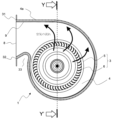
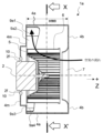
- Figures 1 to 3 are drawings showing the configuration of a blower 1 according to a first embodiment.
- Figure 1 is a perspective view showing the external appearance of blower 1.
- Figures 2 and 3 are cross-sectional views of blower 1.
- Figure 2 is a cross-sectional view of blower 1 taken along a plane that includes the rotation shaft of drive motor 2 in the entire axial direction and is parallel to air outlet 8, and shows the Y-Y' cross section shown in Figure 3.
- Figure 3 is a cross-sectional view of blower 1 taken along a plane that is perpendicular to the rotation shaft of drive motor 2, and shows the XX' cross section shown in Figure 2.
- axial direction refers to the direction parallel to the axis of rotation of the impeller or the axis of rotation of the drive motor.
- Diadial direction refers to the radial direction from the center of rotation of the impeller.
- Circumferential direction refers to the direction in which the impeller rotates.
- Outer circumferential direction refers to the direction along the inner surface of the casing when viewed in the axial direction.
- width refers to the width along the axial direction unless otherwise specified.
- Blower 1 is an example of a centrifugal blower, and includes a drive motor 2, an impeller 3, and a casing 4.
- Drive motor 2 includes a motor body and a rotating shaft that protrudes from the motor body.
- the motor body is made up of a housing and a stator and rotor housed within the housing.
- the rotating shaft is fixed to the rotor within the housing and extends outward from the housing.
- the axial direction in which the rotating shaft protrudes from the motor body of drive motor 2 is the "+Z direction", and the opposite direction, not shown, is the "-Z direction".
- the impeller 3 is attached to the rotating shaft of the drive motor 2, and is driven by the drive motor 2 to perform rotational motion.
- the impeller 3 is an example of a multi-blade impeller, and includes a main plate 5 attached to the rotating shaft of the drive motor 2, and multiple blades 6 attached to the main plate 5.
- the main plate 5 has a circular shape when viewed from above, and the rotating shaft of the drive motor 2 is attached to its center.
- the multiple blades 6 are arranged in a line around the periphery of the main plate 5 at a predetermined interval.
- the casing 4 has an intake port 7 that draws in surrounding air and an outlet port 8 that blows out air.
- the drive motor 2 is attached to the casing 4 so that the impeller 3 can rotate inside the casing 4. When the impeller 3 rotates, it generates an airflow from the axial direction to the radial direction.
- the casing 4 is a scroll casing, and the intake port 7 is located on the +Z side of the axial direction from the drive motor 2 and opens in the axial direction.
- the outlet port 8 opens in a direction perpendicular to the axial direction. By rotating the impeller 3, the blower 1 draws in surrounding air from the intake port 7 and blows it out from the outlet port 8.
- the casing 4 has the function of determining the direction in which the air flows and rectifying the air flow.
- the casing 4 includes a side plate 4a, an upper plate 4b, and a fixed plate 4m, and houses the impeller 3 inside.
- the upper plate 4b is a portion having a surface perpendicular to the axial direction, and the suction port 7 is provided on the upper plate 4b.
- the side plate 4a is integral with the upper plate 4b, and is a portion extending from the upper plate 4b in the axial direction.
- the fixed plate 4m is a member separate from the side plate 4a, and is attached to the side plate 4a so as to face the upper plate 4b.
- the drive motor 2 is attached to the fixed plate 4m.
- the drive motor 2 is provided with a flange 2f, and the drive motor 2 is fixed to the casing 4 by a screw 10 that is passed through the flange 2f and the fixed plate 4m.
- the air outlet 8 is defined by the ends of the side plate 4a, the upper plate 4b, and the fixed plate 4m.
- a tongue portion 33 which is the portion of the curved surface with the largest curvature of the side plate 4a of the casing 4, is formed near the air outlet 8.
- the blower 1 further includes an inner wall 9.
- the inner wall 9 is disposed radially outward from the impeller 3 and is provided on the casing 4 so as to face the inner surface of the casing 4. Therefore, the inner wall 9 is provided so as to stand upright in the axial direction from the fixed plate 4m.
- the inner surface of the casing 4 corresponds to the surface of the side plate 4a facing the inside of the casing 4. In other words, the inner surface of the casing 4 is the surface facing the inside of the casing 4 in a direction other than the axial direction.
- the inner wall 9 may be integrally formed with the fixed plate 4m using the same material, or may be formed separately from the fixed plate 4m and attached to the fixed plate 4m.
- the inner wall 9 extends along the outer circumferential direction while facing the inner surface of the casing 4.
- the distance between the inner wall 9 and the inner surface of the casing 4 is constant in the outer circumferential direction and the axial direction. The distance should be several times (e.g., 2 to 5 times) the thickness of the side plate 4a of the casing 4.
- FIG. 4 is a perspective view showing the exterior of the casing 4 with the fixing plate 4m removed, together with the inner wall 9.
- Figure 5 is a schematic diagram of the inner surface and inner wall 9 of the casing 4 expanded in the outer circumferential direction.
- the up-down direction is the axial direction, and the upward direction corresponds to the +Z direction.
- the left-right direction is the outer circumferential direction.
- the left end is the outlet centrifugal end 31, and the right end is the outlet tongue end 32.
- the outlet centrifugal end 31 is one end parallel to the axial direction of the inner surface of the casing 4, and defines the side of the two sides parallel to the axial direction of the outlet 8 that guides the air blown out radially by centrifugal force from the impeller 3 to the outlet 8.
- the outlet tongue end 32 is the other end parallel to the axial direction of the inner surface of the casing 4, and defines the side of the two sides parallel to the axial direction of the outlet 8 that is closer to the tongue 33 of the casing 4.
- End 21 and end 22 are end 21 and end 22, respectively, which extend along the outer circumferential direction of the inner surface of casing 4.
- End 21 is the end at the extreme end in the -Z direction of the axial direction on the inner surface of casing 4, and is connected to fixed plate 4m.
- End 22 is the end at the extreme end in the +Z direction of the axial direction on the inner surface of casing 4, and is a part that continues from upper plate 4b.
- the length between end 21 and end 22 along the axial direction indicates the width of the inner surface of casing 4, is constant along the outer circumferential direction, and is represented as HW0.
- the end of the inner wall 9 on the -Z side is the part that is attached to the casing 4, and its axial position coincides with the end 21.
- End 25 indicates the end of the inner wall 9 that terminates on the +Z side in the axial direction, and the axial position of end 25 varies depending on the position in the outer circumferential direction, changing to the +Z side as it moves in one direction in the outer circumferential direction.
- the length between end 25 and end 21 along the axial direction indicates the width of the inner wall 9, so the width of the inner wall 9 increases from the outlet tongue side end 32 toward the outlet centrifugal side end 31 along the outer circumferential direction.
- the direction from the outlet tongue side end 32 to the outlet centrifugal side end 31 along the outer circumferential direction corresponds to the direction in which air flows inside the casing 4 after being blown out from the impeller 3.
- the maximum width of the inner wall 9 is HW1, which is the width of the inner wall 9 at the centrifugal end 31 of the outlet.
- the minimum width of the inner wall 9 is HW2 ( ⁇ HW1), which is the width of the inner wall 9 at the tongue end 32 of the outlet.
- HW1 is smaller than HW0, and the part of the inner wall 9 at the extreme end in the +Z axial direction (the part of the end 25 of the inner wall 9 at the centrifugal end 31 of the outlet) is located on the -Z axial side of the end 22 of the inner surface of the casing 4.
- the width of the inner wall 9 is smaller than the width of the inner surface of the casing 4 over the entire outer periphery.
- the rectangles indicated by dotted lines are a schematic representation of the positions of the multiple blades 6.
- the lower end 23 indicates the end-most part of each blade 6 in the -Z axial direction
- the upper end 24 indicates the end-most part of each blade 6 in the +Z axial direction.
- the end 23 of each blade 6 is the part that is attached to the main plate 5, and is located at position HS1 along the axial direction from end 21.
- HS1 is smaller than HW2
- each end 23 of the multiple blades 6 is located on the -Z side along the axial direction of the end-most part of the inner wall 9 in the -Z axial direction.
- each blade 6 terminates in the +Z direction in the axial direction, and is located at HS2 from the end 21 along the axial direction.
- HW1 is larger than HS1 and smaller than HS2, and the part of the inner wall 9 at the very end in the +Z direction in the axial direction is located on the -Z side along the axial direction from the end 24 of each blade 6, and is located on the +Z side along the axial direction from the end 23 of each blade 6.
- the length between the end 24 and the end 23 along the axial direction indicates the width of each blade 6.
- the width of each blade 6 has parts that overlap with the width of the inner wall 9 and parts that do not.
- HS2 is smaller than HW0, and the end 24 of each blade 6 is located on the -Z side along the axial direction from the end 22 of the inner surface of the casing 4.
- the part of the inner wall 9 at the very end in the +Z direction in the axial direction be located on the -Z side along the axial direction rather than the center of the width of the blade 6.
- the height from the fixed plate 4m to the center of the width of the blade 6 in the axial direction is HS3.
- HS3 is expressed as (HS1+HS2)/2, and it is desirable that the inner wall 9 is configured to satisfy the relationship HS1 ⁇ HW2 ⁇ HW1 ⁇ HS3 ⁇ HS2.
- the casing 4 is provided with an inner wall 9 that faces the inner surface of the casing 4. This changes the propagation path of the electromagnetic vibration of the drive motor 2 that propagates through the casing 4. Because the natural frequency of the casing 4 changes, it is possible to suppress resonance of the casing 4 caused by the electromagnetic vibration propagated from the drive motor 2. This makes it possible to reduce the noise generated by the blower 1.
- the inner space of the casing 4 has a symmetrical shape, and there is little effect in suppressing acoustic resonance in the inner space of the casing 4. Therefore, in the blower 1 according to the first embodiment, the part of the inner wall 9 at the extreme end in the +Z direction, which is one direction in the axial direction, is located on the -Z side, which is the opposite direction to the one direction along the axial direction, from the part of the inner surface of the casing 4 at the extreme end in the +Z direction in the axial direction.
- this inner wall 9 are also common to the inner walls 9a, 9b, and 9d of the second, third, and fifth embodiments described below.
- the portion of the inner wall 9 at the extreme end in the +Z direction of the axial direction is located on the opposite side along the axial direction than the extreme end portions of the blades 6 in the +Z direction of the axial direction, and is located on the +Z side along the axial direction than the extreme end portions of the blades 6 in the -Z direction of the axial direction. Therefore, part of the air blown out from the impeller 3 collides with the inner wall 9. In other words, the amount of air blown out from the impeller 3 and colliding with the inner surface of the casing 4 is reduced, so the vibration of the inner surface of the casing 4 can be weakened. Therefore, the noise generated by the blower 1 can be further reduced.
- the configuration and effect of this inner wall 9 are also common to the inner walls 9a, 9b, and 9d of the second, third, and fifth embodiments described below.
- the width of the inner wall 9 may be constant along the outer periphery, but it is preferable to configure the width of the inner wall 9 to vary depending on the position along the outer periphery, as shown in the figure. This will result in a shape in which the symmetry of the inner space of the casing 4 in the outer periphery is lost, making it even more difficult for acoustic resonance to occur in the inner space of the casing 4.
- An example of this configuration is one in which the width of the inner wall 9 increases as it moves in one direction along the outer periphery.
- the large width parts of the inner wall 9 are located on the side where the air flows in the circumferential direction after being blown out from the impeller 3, rather than the small width parts. Since the amount of air colliding with the inner surface of the casing 4 is reduced on the downstream side where the air volume is large, the vibration of the inner surface of the casing 4 can be further weakened and noise can be reduced.
- An example of this configuration is one in which the width of the inner wall 9 increases as it is positioned on the side where the air flows in the circumferential direction after being blown out from the impeller 3.
- Figures 6 and 7 are cross-sectional views of blower 1a according to embodiment 2.
- Figure 6 is a cross-sectional view of blower 1a cut at the same location as the cut surface of Figure 2, and shows the Y-Y' cross section shown in Figure 7.
- Figure 7 is a cross-sectional view of blower 1a cut at the same location as the cut surface of Figure 3, and shows the XX' cross section shown in Figure 6.
- Blower 1a has an inner wall 9a composed of multiple members separated from each other.
- the shape, size, and position of inner wall 9a assembled from multiple members are the same as those of inner wall 9 of blower 1.
- the configuration of blower 1a excluding inner wall 9a is the same as that of blower 1 excluding inner wall 9.
- Figure 8 is a schematic diagram of the inner surface of casing 4 and inner wall 9a of blower 1a expanded in the outer circumferential direction. As can be seen from Figure 8, the multiple members that make up inner wall 9a are arranged side by side in the outer circumferential direction.
- an inner wall 9a composed of six members 9a1 to 9a6 is shown as an example.
- Resonance of the inner wall 9a which is assembled from multiple mutually separated members 9a1-9a6, is suppressed more than in the case of an inner wall 9 made of a single member.
- the shape and size of each component can be changed as appropriate, it is easy to change the design of the inner wall 9a in terms of its shape and size. For example, since the electromagnetic vibration of the drive motor 2 is propagated via the flange 2f and the screw 10, it is expected that the inner wall 9a as a whole will be appropriately designed simply by appropriately changing the members corresponding to the parts of the inner wall 9a close to the flange 2f or the screw 10.
- the inner wall 9a is composed of multiple members 9a1-9a6, this also contributes to cost reduction.
- the shape and size of each member is designed, and the inner wall 9a is prototyped according to that design.
- the design of the inner wall 9a is subsequently changed.
- the design change can be made by simply replacing a specific member among the multiple members 9a1-9a6, the cost of the design change can be reduced compared to when the integral inner wall 9 is remade as in embodiment 1.
- the casing 4 may be configured so that the attached inner wall 9a can be removed from the casing 4 on a member-by-member basis.
- the widths of the multiple members that make up the inner wall 9a along the outer periphery may be uneven, but they may also be the same.
- the distance from the rotating shaft of the drive motor 2 to the inner surface of the casing 4 varies depending on the angle of the rotating shaft, and as the distance increases, the wavelength becomes longer and the natural frequency becomes lower. Because the casing 4 is a scroll casing, the distance changes depending on the angle of the rotating shaft, so even if the distances are equal, the natural frequency changes.
- the width of the inner wall 9a increases in one direction along the outer circumferential direction, similar to the inner wall 9 in the first embodiment.
- the members 9a1 to 9a6 may be configured so that the width of each member constituting the inner wall 9a is constant along the outer circumferential direction, and the members 9a1 to 9a6 have a larger width toward the outer circumferential direction from the tongue end 32 of the outlet to the centrifugal end 31 of the outlet.
- the assembled inner wall 9a is configured so that the width of the inner wall increases in a stepped manner from the tongue end 32 of the outlet to the centrifugal end 31 of the outlet.
- the width of the inner wall 9a is smaller than the width of the inner surface of the casing 4 along the outer circumferential direction.
- Figures 9 and 10 are cross-sectional views of blower 1b according to embodiment 3.
- Figure 9 is a cross-sectional view of blower 1b cut at the same location as the cut surface of Figure 2, and shows the Y-Y' cross section shown in Figure 10.
- Figure 10 is a cross-sectional view of blower 1b cut at the same location as the cut surface of Figure 3, and shows the XX' cross section shown in Figure 9.
- Blower 1b is disposed radially outward of impeller 3 and has inner wall 9b provided on casing 4 so as to face the inner surface of casing 4.
- Inner wall 9b extends from outlet centrifugal end 31 along the outer circumferential direction to outlet tongue end 32. Width W1 of inner wall 9b is constant along the outer circumferential direction. Meanwhile, distance D1 between inner wall 9b and inner surface of casing 4 varies depending on axial position.
- One embodiment is a configuration in which distance D1 increases along the outer circumferential direction as it moves away from fixed plate 4m of casing 4 in the axial direction.
- Inner wall 9b may be integrally formed with fixed plate 4m using the same material, or may be formed separately from fixed plate 4m and attached to fixed plate 4m.
- the configuration of blower 1b excluding inner wall 9b is the same as blower 1 excluding inner wall 9.
- the distance D1 between the inner wall 9b and the inner surface of the casing varies depending on the axial position, so that the natural frequency can be changed in the axial direction, suppressing resonance of the electromagnetic vibration of the drive motor 2 in the casing 4.
- the width W1 of inner wall 9b is the same regardless of the position in the outer circumferential direction, but it may be different depending on the position in the outer circumferential direction, as with inner wall 9 in embodiment 1.
- FIG. 11 is a cross-sectional view showing a blower 1c according to the fourth embodiment, and the location of the cut surface is the same as that of FIG. 3.
- the blower 1c further includes a partition member 9c in addition to the blower 1 of the first embodiment.
- the partition member 9c is a member that connects the inner wall 9 and the inner surface of the casing 4, and divides the gap between the inner wall 9 and the inner surface of the casing 4 in the outer circumferential direction.
- the width of the partition member 9c is, for example, the same as the width of the part of the inner wall 9 to which the partition member 9c is connected. At least one partition member 9c is provided, and when a plurality of partition members 9c are provided as shown in FIG.
- the partition member 9c may be integrally formed with the inner wall 9 using the same material, or may be formed separately from the inner wall 9 and attached to the inner wall 9. Alternatively, the partition member 9c may be integrally formed with the same material as the side plate 4a of the casing, or may be formed separately from the side plate 4a and attached to the side plate 4a.
- the partition member 9c separates the gap between the inner wall 9 and the inner surface of the casing 4 in the outer circumferential direction, thereby suppressing the airflow flowing through the gap in the outer circumferential direction, thereby suppressing noise caused by the airflow flowing through the gap.
- the partition member 9c may be provided in the blower 1a according to the second embodiment.
- the partition members 9c partition the gap between the inner wall 9a and the inner surface of the casing 4 in the outer circumferential direction. It is preferable that the partition member 9c is integrally formed from the same material as each member of the inner wall 9a.
- the partition member 9c may be provided in the blower 1b according to the third embodiment.
- Figures 12 and 13 are cross-sectional views of blower 1d according to embodiment 5.
- Figure 12 is a cross-sectional view of blower 1d cut at the same location as the cut surface of Figure 2, and shows the Y-Y' cross section shown in Figure 13.
- Figure 13 is a cross-sectional view of blower 1d cut at the same location as the cut surface of Figure 3, and shows the XX' cross section shown in Figure 12.
- Blower 1d is disposed radially outward of impeller 3 and has an inner wall 9d provided on casing 4 facing the inner surface of casing 4.
- Inner wall 9d has multiple portions arranged side by side in the outer circumferential direction. Hereinafter, each of these multiple portions will be referred to as an "inner wall portion.”
- inner wall portions 9d1 to 9d9 There are nine inner wall portions exemplified in this embodiment, which will be referred to as inner wall portions 9d1 to 9d9.
- the configuration of blower 1d excluding inner wall 9d is the same as blower 1 excluding inner wall 9.
- the multiple inner wall portions 9d1 to 9d9 are arranged at a distance from each other.
- the inner wall portion 9d1 is arranged at the very end on the side of the outlet centrifugal end 31 of the casing 4, and the inner wall portion 9d9 is arranged at the very end on the side of the outlet tongue end 32 of the casing 4.
- Each of the multiple inner wall portions 9d2 to 9d8 is configured so that the distance between each member and the inner surface of the casing 4 increases from the outlet tongue end 32 toward the outlet centrifugal end 31 along the outer circumferential direction.
- the distance between the inner wall portion 9d1 and the inner surface of the casing 4 is constant along the outer periphery.
- the inner wall portion 9d9 is divided into two parts, and in the first part, the distance between the inner surface of the casing 4 is constant along the outer periphery from the end at the outlet tongue side end 32.
- the second part is the part from the first part to the other end of the inner wall portion 9d9. In the second part, the distance between the inner surface of the casing 4 increases along the outer periphery toward the outlet centrifugal side end 31.
- the ends of adjacent inner wall portions of the multiple inner wall portions 9d1 to 9d9 are arranged at a distance from each other in the direction facing the inner surface of the casing 4.
- the width of the inner wall 9d as a whole is constant along the outer periphery.
- the inner wall 9d has multiple inner wall portions 9d2 to 9d8 in which the gap between them and the inner surface of the casing 4 becomes larger in one direction in the outer circumferential direction.
- the distance between the end portion of one of the adjacent inner wall portions in one direction in the outer circumferential direction and the inner surface of the casing 4 is larger than the distance between the end portion of the other inner wall portion in the opposite direction to the one direction in the outer circumferential direction and the inner surface of the casing.
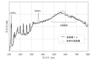
- Figures 14 and 15 are graphs showing the measurement results.
- the measurement results are expressed as a waveform obtained by Fourier transforming the measured noise value by FFT (Fast Fourier Transformation).
- Figure 14 shows the value measured at a point 1 meter away from the center of the intake port 7 of the casing 4 toward the outside of the blower 1 along the axial direction.
- Figure 15 shows the value measured at a point 1 meter away from the center of the intake port 7 in the Y-Y' direction shown in Figure 13 along a direction perpendicular to the opening surface of the outlet port 8.
- the power frequency used for the measurement is 60 Hz.
- the solid line shows the measurement result for the blower 1d according to this embodiment, and the dotted line shows the measurement result for a conventional blower at the same location as the blower 1d.
- the conventional blower is a blower 1d from which the inner wall 9d has been removed.
- blower 1d the noise peaks seen at frequencies of 120 Hz and 360 Hz are vibration noises caused by the casing 4 resonating with the electromagnetic vibrations of the drive motor 2. In contrast, in blower 1d, these noise peaks are reduced or eliminated. Also, in the conventional blower, the areas where the noise level rises over a wide frequency band (the band marked "resonance band” in the figure) indicate that acoustic resonance is occurring in the internal space of the casing 4. In contrast, acoustic resonance is reduced in blower 1d. As can be seen from the above, noise is reduced by blower 1d being provided with inner wall 9d.
- the width of the inner wall 9d is constant in the outer circumferential direction, but may vary in the outer circumferential direction, as in the first and second embodiments. Also, as in the third embodiment, each inner wall portion of the inner wall 9d may be configured so that the distance between the inner wall surface of the casing 4 and the inner wall surface varies depending on the axial position. Also, as in the fourth embodiment, the blower 1d may further include a partition member that separates the gap between the inner wall 9d and the inner surface of the casing 40 in the outer circumferential direction.
- FIG. 16 is a front view showing the appearance of blower 1e according to embodiment 6.
- the side facing suction port 7 is the front of blower 1e.
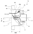
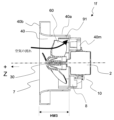
- Fig. 17 is a cross-sectional view of blower 1e taken along a plane including the entire axial direction of the rotation shaft of drive motor 2, showing the W-W' cross section shown in Fig. 16.
- the blower 1e is an example of an axial flow blower, and includes a drive motor 2, an impeller 30, and a casing 40.
- the impeller 30 is attached to the rotating shaft of the drive motor 2, and is driven by the drive motor 2 to perform rotational motion.
- the impeller 30 includes a plurality of blades 60 that constitute a propeller fan.
- the casing 40 includes an intake port 7 that draws in surrounding air, and an exhaust port 8 that blows out air.
- the drive motor 2 is attached to the casing 40 so that the impeller 30 can rotate inside the casing 40. When the impeller 30 rotates, it generates an airflow from the front to the rear of the blower 1e. Both the intake port 7 and the exhaust port 8 open in the axial direction.
- the intake port 7 is located on the +Z side of the impeller 30 in the axial direction (i.e., the front side), and the exhaust port 8 is located on the -Z side of the impeller 30 in the axial direction (i.e., the back side).
- the casing 40 includes a side plate 40a, an upper plate 40b, and a fixing member 40m, and houses the impeller 30 inside.
- the upper plate 40b is a portion having a surface perpendicular to the axial direction, and the suction port 7 is provided on the upper plate 40b.
- the side plate 40a is integral with the upper plate 40b, extends axially from the upper plate 40b, and is disposed so as to surround the impeller 3 in the circumferential direction.
- the fixing member 40m is attached to the side plate 40a, and the drive motor 2 is attached to the fixing member 40m.
- the drive motor 2 is fixed to the casing 40 with screws 10.
- Blower 1e further includes an inner wall 90.
- the inner wall 90 is disposed radially outward from impeller 30 and is provided on casing 40 so as to face the inner surface of casing 40.
- the inner surface of casing 40 corresponds to the surface of side plate 40a facing the inside of casing 40.
- the inner wall 90 is integrally formed from the same material as side plate 40a, but may be formed separately from side plate 40a and attached to side plate 40a or fixed member 40m.
- the inner wall 90 has an annular structure that extends along the outer circumferential direction while facing the inner surface of casing 4. The distance between the inner wall 90 and the inner surface of casing 4 is constant in the outer circumferential direction and the axial direction.
- Figure 18 is a schematic diagram of the inner surface and inner wall 90 of the casing 40 expanded in the outer circumferential direction.
- the up-down direction is the axial direction, and the upward direction corresponds to the +Z direction.
- the left-right direction is the outer circumferential direction, and the left end and the right end indicate the same location.
- the lower end and upper end are end 41 and end 42, respectively, that extend along the outer circumferential direction of the inner surface of the casing 40.
- End 41 is the end at the extreme end in the -Z direction of the axial direction on the inner surface of the casing 40, and is connected to the fixing member 40m.
- End 42 is the end at the extreme end in the +Z direction of the axial direction on the inner surface of the casing 40, and is a part that continues from the upper plate 40b.
- the length between end 41 and end 42 along the axial direction indicates the width of the inner surface of the casing 40, is constant along the outer circumferential direction, and is designated HW3.
- the end of the inner wall 90 on the -Z axial side is the part that is attached to the casing 40, and its axial position coincides with the end 41.
- the end 45 indicates the end of the inner wall 90 that terminates on the +Z axial side, and the axial position of the end 45 differs depending on the position in the outer circumferential direction, and changes periodically according to the position in the outer circumferential direction. Since the length between the end 45 and the end 41 along the axial direction indicates the width of the inner wall 90, it can also be said that the width of the inner wall 90 changes periodically according to the position in the outer circumferential direction.
- the minimum width of the inner wall 90 is HW4, and the maximum width is HW5.
- HW5 is smaller than HW3, and the part of the inner wall 90 at the very end in the +Z axial direction (the part of the end 45 where the width of the inner wall 9 is HW5) is located on the -Z axial side of the end 42 on the inner surface of the casing 40.
- the width of the inner wall 90 is smaller than the width of the inner surface of the casing 40 over the outer circumferential direction.
- the closed curve shown by the dotted line is a schematic representation of the position of each blade 60.
- End 43 shown by a black circle is the endmost part of each blade 60 in the -Z axial direction
- end 44 shown by a black circle is the endmost part of each blade 60 in the +Z axial direction.
- Ends 43 and 44 of each blade 60 are located at heights HP1 and HP2, respectively, along the axial direction from end 41 of the inner surface of casing 40.
- HP1 is smaller than HW4, and end 43 of each blade 60 is located on the +Z axial side of end 21 of the inner surface of casing 4.
- HW5 is also larger than HP1 and smaller than HP2, and the portion of the inner wall 90 at the extreme end in the +Z axial direction is located on the -Z axial side of the end 44 of each blade 60, and on the +Z axial side of the end 43 of each blade 6.
- the length between end 44 and end 43 along the axial direction indicates the width of each blade 60.
- the width of each blade 60 has parts that overlap with the width of the inner wall 9 and parts that do not.
- HP2 is smaller than HW3, and end 44 of each blade 60 is located on the -Z axial side of end 42 of the inner surface of the casing 4.
- an inner wall 90 that faces the inner surface of the casing 4 is provided on the casing 40, so that the natural frequency of the casing 40 changes, and it is possible to prevent the casing 40 from resonating with the electromagnetic vibrations of the drive motor 2.
- the portion of the inner wall 90 at the extreme end in the +Z direction which is one direction in the axial direction, is located on the -Z side, which is the opposite direction along the axial direction, from the portion of the inner surface of the casing at the extreme end in the +Z direction in the axial direction. Since the internal space of the casing 4 has a shape that loses axial symmetry, acoustic resonance in the internal space of the casing 4 is suppressed.
- the configuration and effects of this inner wall 90 are also common to the inner wall 91 of embodiment 7, which will be described later.
- the portion of the inner wall 90 at the extreme end in the +Z direction in the axial direction is located closer to the -Z direction in the axial direction than the extreme end portions of the plurality of blades 60 in the +Z direction in the axial direction, and is located closer to the +Z direction in the axial direction than the extreme end portions of the plurality of blades 60 in the -Z direction in the axial direction. Since the amount of air blown out from the impeller 30 and colliding with the inner surface of the casing 40 is reduced, the vibration of the side plate 40a of the casing 40 can be weakened more than in the past.
- the configuration and effects of this inner wall 90 are also common to the inner wall 91 of embodiment 7 described below.
- the width of the inner wall 90 may be constant along the outer periphery, but it is preferable to configure the width of the inner wall 90 to vary depending on the position along the outer periphery, as shown in the figure. This will impair the symmetry of the inner space of the casing 40 in the outer periphery, making it even less likely that acoustic resonance will occur in the inner space of the casing 40.
- An example of this configuration is one in which the width of the inner wall 90 changes periodically depending on the position along the outer periphery.
- the period for changing the width of the inner wall 90 may be varied, as shown in FIG. 19.
- the inner wall 90 has three inner wall sections 90a, 90b, and 90c.
- the angles of one period of the change in the width of the inner wall 90 differ between the inner wall sections 90a, 90b, and 90c at 1:2:5.
- the inner wall 90 may be composed of multiple members that are separated from one another and arranged side by side in the outer circumferential direction. Also, as in embodiment 3, the inner wall 90 may be configured so that the distance between the inner wall 90 and the inner surface of the casing 40 varies depending on the axial position. Also, as in embodiment 4, the blower 1e may further include a partition member that separates the gap between the inner wall 90 and the inner surface of the casing 40 in the outer circumferential direction.
- FIG. 20 is a diagram showing the external appearance of blower 1f according to embodiment 7, and is a front view of inlet 7 of blower 1f.
- Fig. 21 is a cross-sectional view of blower 1f taken along a cutting plane including the entire axial direction of the rotating shaft of drive motor 2, and shows the W-W' cross section shown in Fig. 20.
- Blower 1f is disposed radially outward of impeller 30 and has an inner wall 91 provided on casing 40 so as to face the inner surface of casing 40.
- Inner wall 91 has multiple inner wall portions.
- Inner wall 91 is formed by connecting multiple inner wall portions in a ring shape.
- the number of inner wall portions exemplified in this embodiment is 11.
- the configuration of blower 1f excluding inner wall 91 is the same as blower 1e excluding inner wall 90.
- each inner wall portion is configured so that the distance between it and the inner surface of casing 40 increases in one direction in the outer circumferential direction.
- the distance between the end portion of one of the adjacent inner wall portions in one outer circumferential direction and the inner surface of casing 40 is greater than the distance between the end portion of the other inner wall portion in the opposite direction to the one outer circumferential direction and the inner surface of casing 40.
- the inner wall 91 is constructed from a single member made of the same material, but it may be a combination of multiple members divided into individual inner wall portions. Also, as in embodiment 5, the multiple inner wall portions of the inner wall 91 may be arranged in a ring shape while being spaced apart from each other. Also, the width of the inner wall 9d as a whole is constant in the outer circumferential direction, but as in embodiment 6, it may vary at the position in the outer circumferential direction. Also, as in embodiment 3, the inner wall 91 may be configured so that the distance between it and the inner surface of the casing 40 varies depending on the axial position. Also, as in embodiment 4, the blower 1f may further include a partition member that partitions the gap between the inner wall 91 and the inner surface of the casing 40 in the outer circumferential direction.
- Reference Signs List 1 1a to 1f blower, 2 drive motor, 3, 30 impeller, 4, 40 casing, 6, 60 blades, 7 intake port, 8 outlet port, 9, 9a, 9b, 9d, 90, 91 inner wall, 9c partition member, 21 to 25, 41 to 45 end portion, 31 centrifugal side end portion of outlet port, 32 tongue side end portion of outlet port
Landscapes
- Engineering & Computer Science (AREA)
- Mechanical Engineering (AREA)
- General Engineering & Computer Science (AREA)
- Structures Of Non-Positive Displacement Pumps (AREA)
Priority Applications (2)
| Application Number | Priority Date | Filing Date | Title |
|---|---|---|---|
| JP2024574211A JPWO2024161627A1 (https=) | 2023-02-03 | 2023-02-03 | |
| PCT/JP2023/003557 WO2024161627A1 (ja) | 2023-02-03 | 2023-02-03 | 送風機 |
Applications Claiming Priority (1)
| Application Number | Priority Date | Filing Date | Title |
|---|---|---|---|
| PCT/JP2023/003557 WO2024161627A1 (ja) | 2023-02-03 | 2023-02-03 | 送風機 |
Publications (1)
| Publication Number | Publication Date |
|---|---|
| WO2024161627A1 true WO2024161627A1 (ja) | 2024-08-08 |
Family
ID=92146230
Family Applications (1)
| Application Number | Title | Priority Date | Filing Date |
|---|---|---|---|
| PCT/JP2023/003557 Ceased WO2024161627A1 (ja) | 2023-02-03 | 2023-02-03 | 送風機 |
Country Status (2)
| Country | Link |
|---|---|
| JP (1) | JPWO2024161627A1 (https=) |
| WO (1) | WO2024161627A1 (https=) |
Citations (7)
| Publication number | Priority date | Publication date | Assignee | Title |
|---|---|---|---|---|
| JPH0374600A (ja) * | 1989-08-11 | 1991-03-29 | Mitsubishi Electric Corp | 送風機 |
| JPH04159500A (ja) * | 1990-10-22 | 1992-06-02 | Hitachi Ltd | 遠心送風機 |
| JPH0610892A (ja) * | 1992-06-30 | 1994-01-21 | Hitachi Ltd | 軸流形送風機及びこれを用いた空気調和機 |
| JPH08135599A (ja) * | 1994-11-14 | 1996-05-28 | Toshiba Corp | 遠心送風機 |
| US20160146216A1 (en) * | 2014-11-25 | 2016-05-26 | Delta Electronics, Inc. | Centrifugal fan |
| WO2016170831A1 (ja) * | 2015-04-22 | 2016-10-27 | 三菱重工オートモーティブサーマルシステムズ株式会社 | 遠心式送風機 |
| WO2021085086A1 (ja) * | 2019-10-31 | 2021-05-06 | 株式会社デンソー | 送風機 |
-
2023
- 2023-02-03 WO PCT/JP2023/003557 patent/WO2024161627A1/ja not_active Ceased
- 2023-02-03 JP JP2024574211A patent/JPWO2024161627A1/ja active Pending
Patent Citations (7)
| Publication number | Priority date | Publication date | Assignee | Title |
|---|---|---|---|---|
| JPH0374600A (ja) * | 1989-08-11 | 1991-03-29 | Mitsubishi Electric Corp | 送風機 |
| JPH04159500A (ja) * | 1990-10-22 | 1992-06-02 | Hitachi Ltd | 遠心送風機 |
| JPH0610892A (ja) * | 1992-06-30 | 1994-01-21 | Hitachi Ltd | 軸流形送風機及びこれを用いた空気調和機 |
| JPH08135599A (ja) * | 1994-11-14 | 1996-05-28 | Toshiba Corp | 遠心送風機 |
| US20160146216A1 (en) * | 2014-11-25 | 2016-05-26 | Delta Electronics, Inc. | Centrifugal fan |
| WO2016170831A1 (ja) * | 2015-04-22 | 2016-10-27 | 三菱重工オートモーティブサーマルシステムズ株式会社 | 遠心式送風機 |
| WO2021085086A1 (ja) * | 2019-10-31 | 2021-05-06 | 株式会社デンソー | 送風機 |
Also Published As
| Publication number | Publication date |
|---|---|
| JPWO2024161627A1 (https=) | 2024-08-08 |
Similar Documents
| Publication | Publication Date | Title |
|---|---|---|
| JP5244620B2 (ja) | 送風装置 | |
| JP5351401B2 (ja) | 圧縮機 | |
| JP6221046B2 (ja) | 送風装置 | |
| JP3567086B2 (ja) | 送風羽根及び回転電機 | |
| WO2009130891A1 (ja) | 遠心送風機および遠心送風機の騒音低減方法 | |
| JP5135966B2 (ja) | 遠心送風機 | |
| JP2003120589A (ja) | ラジエータファンおよびこれを用いたエンジン冷却装置 | |
| JP7308985B2 (ja) | 遠心送風機及び空気調和装置 | |
| JPH07332284A (ja) | 多翼送風機 | |
| JP5309516B2 (ja) | 遠心送風機 | |
| WO2024161627A1 (ja) | 送風機 | |
| CN202176522U (zh) | 鼓风机和风扇框架 | |
| JP2006189000A (ja) | 空気調和室外機ユニット | |
| JP2019074030A (ja) | 遠心ファン | |
| JP7486667B2 (ja) | 羽根車および遠心送風機 | |
| JP2701603B2 (ja) | 遠心送風機 | |
| JP3912331B2 (ja) | 遠心形流体機械 | |
| JP7251726B2 (ja) | 送風機 | |
| JP2003035298A (ja) | 遠心送風機 | |
| JP4621420B2 (ja) | 回転電機 | |
| JP4174278B2 (ja) | 送風機のファンカバー | |
| JP7819688B2 (ja) | 遠心送風機 | |
| JP6074611B2 (ja) | 送風装置 | |
| JP7826147B2 (ja) | 軸流ファン | |
| JP6152582B2 (ja) | 送風装置 |
Legal Events
| Date | Code | Title | Description |
|---|---|---|---|
| 121 | Ep: the epo has been informed by wipo that ep was designated in this application |
Ref document number: 23919764 Country of ref document: EP Kind code of ref document: A1 |
|
| ENP | Entry into the national phase |
Ref document number: 2024574211 Country of ref document: JP Kind code of ref document: A |
|
| WWE | Wipo information: entry into national phase |
Ref document number: 2024574211 Country of ref document: JP |
|
| NENP | Non-entry into the national phase |
Ref country code: DE |
|
| 122 | Ep: pct application non-entry in european phase |
Ref document number: 23919764 Country of ref document: EP Kind code of ref document: A1 |