WO2024075445A1 - 半導体モジュール、半導体装置、及び車両 - Google Patents
半導体モジュール、半導体装置、及び車両 Download PDFInfo
- Publication number
- WO2024075445A1 WO2024075445A1 PCT/JP2023/031780 JP2023031780W WO2024075445A1 WO 2024075445 A1 WO2024075445 A1 WO 2024075445A1 JP 2023031780 W JP2023031780 W JP 2023031780W WO 2024075445 A1 WO2024075445 A1 WO 2024075445A1
- Authority
- WO
- WIPO (PCT)
- Prior art keywords
- recess
- recesses
- lead
- semiconductor
- semiconductor module
- Prior art date
- Legal status (The legal status is an assumption and is not a legal conclusion. Google has not performed a legal analysis and makes no representation as to the accuracy of the status listed.)
- Ceased
Links
Images






Classifications
-
- H—ELECTRICITY
- H10—SEMICONDUCTOR DEVICES; ELECTRIC SOLID-STATE DEVICES NOT OTHERWISE PROVIDED FOR
- H10W—GENERIC PACKAGES, INTERCONNECTIONS, CONNECTORS OR OTHER CONSTRUCTIONAL DETAILS OF DEVICES COVERED BY CLASS H10
- H10W74/00—Encapsulations, e.g. protective coatings
- H10W74/10—Encapsulations, e.g. protective coatings characterised by their shape or disposition
- H10W74/111—Encapsulations, e.g. protective coatings characterised by their shape or disposition the semiconductor body being completely enclosed
-
- H—ELECTRICITY
- H10—SEMICONDUCTOR DEVICES; ELECTRIC SOLID-STATE DEVICES NOT OTHERWISE PROVIDED FOR
- H10W—GENERIC PACKAGES, INTERCONNECTIONS, CONNECTORS OR OTHER CONSTRUCTIONAL DETAILS OF DEVICES COVERED BY CLASS H10
- H10W40/00—Arrangements for thermal protection or thermal control
- H10W40/20—Arrangements for cooling
- H10W40/25—Arrangements for cooling characterised by their materials
- H10W40/255—Arrangements for cooling characterised by their materials having a laminate or multilayered structure, e.g. direct bond copper [DBC] ceramic substrates
-
- H—ELECTRICITY
- H10—SEMICONDUCTOR DEVICES; ELECTRIC SOLID-STATE DEVICES NOT OTHERWISE PROVIDED FOR
- H10W—GENERIC PACKAGES, INTERCONNECTIONS, CONNECTORS OR OTHER CONSTRUCTIONAL DETAILS OF DEVICES COVERED BY CLASS H10
- H10W70/00—Package substrates; Interposers; Redistribution layers [RDL]
- H10W70/60—Insulating or insulated package substrates; Interposers; Redistribution layers
- H10W70/67—Insulating or insulated package substrates; Interposers; Redistribution layers characterised by their insulating layers or insulating parts
- H10W70/68—Shapes or dispositions thereof
- H10W70/685—Shapes or dispositions thereof comprising multiple insulating layers
-
- H—ELECTRICITY
- H10—SEMICONDUCTOR DEVICES; ELECTRIC SOLID-STATE DEVICES NOT OTHERWISE PROVIDED FOR
- H10W—GENERIC PACKAGES, INTERCONNECTIONS, CONNECTORS OR OTHER CONSTRUCTIONAL DETAILS OF DEVICES COVERED BY CLASS H10
- H10W72/00—Interconnections or connectors in packages
-
- H—ELECTRICITY
- H10—SEMICONDUCTOR DEVICES; ELECTRIC SOLID-STATE DEVICES NOT OTHERWISE PROVIDED FOR
- H10W—GENERIC PACKAGES, INTERCONNECTIONS, CONNECTORS OR OTHER CONSTRUCTIONAL DETAILS OF DEVICES COVERED BY CLASS H10
- H10W72/00—Interconnections or connectors in packages
- H10W72/071—Connecting or disconnecting
- H10W72/076—Connecting or disconnecting of strap connectors
-
- H—ELECTRICITY
- H10—SEMICONDUCTOR DEVICES; ELECTRIC SOLID-STATE DEVICES NOT OTHERWISE PROVIDED FOR
- H10W—GENERIC PACKAGES, INTERCONNECTIONS, CONNECTORS OR OTHER CONSTRUCTIONAL DETAILS OF DEVICES COVERED BY CLASS H10
- H10W74/00—Encapsulations, e.g. protective coatings
-
- H—ELECTRICITY
- H10—SEMICONDUCTOR DEVICES; ELECTRIC SOLID-STATE DEVICES NOT OTHERWISE PROVIDED FOR
- H10W—GENERIC PACKAGES, INTERCONNECTIONS, CONNECTORS OR OTHER CONSTRUCTIONAL DETAILS OF DEVICES COVERED BY CLASS H10
- H10W74/00—Encapsulations, e.g. protective coatings
- H10W74/10—Encapsulations, e.g. protective coatings characterised by their shape or disposition
- H10W74/111—Encapsulations, e.g. protective coatings characterised by their shape or disposition the semiconductor body being completely enclosed
- H10W74/127—Encapsulations, e.g. protective coatings characterised by their shape or disposition the semiconductor body being completely enclosed characterised by arrangements for sealing or adhesion
-
- H—ELECTRICITY
- H10—SEMICONDUCTOR DEVICES; ELECTRIC SOLID-STATE DEVICES NOT OTHERWISE PROVIDED FOR
- H10W—GENERIC PACKAGES, INTERCONNECTIONS, CONNECTORS OR OTHER CONSTRUCTIONAL DETAILS OF DEVICES COVERED BY CLASS H10
- H10W74/00—Encapsulations, e.g. protective coatings
- H10W74/40—Encapsulations, e.g. protective coatings characterised by their materials
-
- H—ELECTRICITY
- H10—SEMICONDUCTOR DEVICES; ELECTRIC SOLID-STATE DEVICES NOT OTHERWISE PROVIDED FOR
- H10W—GENERIC PACKAGES, INTERCONNECTIONS, CONNECTORS OR OTHER CONSTRUCTIONAL DETAILS OF DEVICES COVERED BY CLASS H10
- H10W40/00—Arrangements for thermal protection or thermal control
-
- H—ELECTRICITY
- H10—SEMICONDUCTOR DEVICES; ELECTRIC SOLID-STATE DEVICES NOT OTHERWISE PROVIDED FOR
- H10W—GENERIC PACKAGES, INTERCONNECTIONS, CONNECTORS OR OTHER CONSTRUCTIONAL DETAILS OF DEVICES COVERED BY CLASS H10
- H10W72/00—Interconnections or connectors in packages
- H10W72/60—Strap connectors, e.g. thick copper clips for grounding of power devices
- H10W72/631—Shapes of strap connectors
-
- H—ELECTRICITY
- H10—SEMICONDUCTOR DEVICES; ELECTRIC SOLID-STATE DEVICES NOT OTHERWISE PROVIDED FOR
- H10W—GENERIC PACKAGES, INTERCONNECTIONS, CONNECTORS OR OTHER CONSTRUCTIONAL DETAILS OF DEVICES COVERED BY CLASS H10
- H10W76/00—Containers; Fillings or auxiliary members therefor; Seals
- H10W76/10—Containers or parts thereof
-
- H—ELECTRICITY
- H10—SEMICONDUCTOR DEVICES; ELECTRIC SOLID-STATE DEVICES NOT OTHERWISE PROVIDED FOR
- H10W—GENERIC PACKAGES, INTERCONNECTIONS, CONNECTORS OR OTHER CONSTRUCTIONAL DETAILS OF DEVICES COVERED BY CLASS H10
- H10W90/00—Package configurations
- H10W90/701—Package configurations characterised by the relative positions of pads or connectors relative to package parts
- H10W90/761—Package configurations characterised by the relative positions of pads or connectors relative to package parts of strap connectors
- H10W90/764—Package configurations characterised by the relative positions of pads or connectors relative to package parts of strap connectors between a chip and a stacked insulating package substrate, interposer or RDL
Definitions
- the present invention relates to a semiconductor module, a semiconductor device, and a vehicle.
- Some power conversion devices such as inverter devices, are equipped with semiconductor devices having circuit boards on which semiconductor elements such as IGBTs (Insulated Gate Bipolar Transistors), power MOSFETs (Metal Oxide Semiconductor Field Effect Transistors), and FWDs (Free Wheeling Diodes) are mounted.
- the circuit board includes a wiring board in which a conductor pattern is provided on the surface of an insulating substrate, and circuit components such as semiconductor elements that are arranged on the wiring board.
- a conductor plate called a lead may be used as a conductive member that electrically connects the electrodes on the surface (upper surface) of the semiconductor element opposite the surface facing the wiring board to the conductor pattern of the wiring board.
- Patent Document 1 describes a semiconductor device in which the side walls of the dimples formed on the lead frame have inwardly protruding return portions, and the dimples are connected by grooves.
- Patent Document 2 describes a semiconductor device in which at least four return portions are formed by protruding part of the inner peripheral wall inward on each of a plurality of dimples formed on a lead frame.
- Patent Document 3 describes a semiconductor device in which a plurality of dimples formed on a lead frame are each formed with a return portion by protruding part of the inner peripheral wall inward on each of the plurality of dimples, and the plurality of dimples include two types of dimples with return portions that differ in orientation.
- Patent Document 4 describes a semiconductor device in which a large dimple that opens onto at least one of the main surfaces of a die pad in a lead frame and a small dimple that opens onto the inner surface of the large dimple are formed.
- Patent Document 5 describes a semiconductor device in which a number of rectangular recesses are arranged vertically and horizontally at approximately equal intervals on the surface of a metal plate to which a semiconductor element is fixed, in a region other than the region where the semiconductor element is mounted.
- the recesses called dimples formed on the surface of the lead are shaped to have walls parallel to the sides of the lead in a planar view, or are arranged in a direction perpendicular to the sides of the lead. For this reason, when peeling occurs in the encapsulant at a position that is the side of the lead in a planar view, the peeling often progresses in a direction perpendicular to that side.
- the present invention was made in consideration of these points, and one of its objectives is to prevent the progression of peeling at the interface between the lead that is joined to the electrode of the semiconductor element by a bonding material and the sealing material.
- a semiconductor module comprises a circuit board on which a semiconductor element is mounted, leads joined by a bonding material to electrodes on the upper surface of the semiconductor element, and a sealing material for sealing the semiconductor element and the leads, the leads having a plurality of recesses on the upper surface opposite the lower surface facing the electrode at the bonding portion joined to the electrode, the recesses having a polygonal shape with sides whose bottom surface in a plan view extends in a direction that is not perpendicular to any of the sides of the bonding portion, and each of the plurality of recesses has a return portion protruding from a wall surface.
- the present invention makes it possible to prevent the progression of peeling at the interface between the lead bonded to the electrode of the semiconductor element by a bonding material and the sealing material.
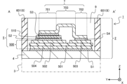
- FIG. 1 is a top view illustrating a configuration example of a semiconductor device according to an embodiment; This is a cross-sectional view of the semiconductor device of Figure 1 along line A-A'.
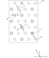
- FIG. 2 is an enlarged partial top view of a region R in FIG. 1 .
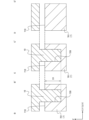
- 4A and 4B are cross-sectional views of the portion shown in FIG. 3 taken along lines B-B', C-C', and D-D'.
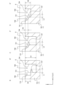
- FIG. 2 is a top view illustrating a first step in an example of a method for forming a recess. These are cross-sectional views taken along lines B-B', C-C', and D-D' in Figure 5.
- FIG. 11 is a top view illustrating a second step in the example of a method for forming a recess.
- FIG. 4 is a top view illustrating a recess formed by the first step and the second step.
- FIG. 11 is a top view illustrating a third step in the example of a method for forming a recess. These are cross-sectional views taken along lines B-B', C-C', and D-D' in Figure 10.
- 11 is a top view illustrating a conventional example of a recess for preventing peeling at the interface between a first bonding portion of a lead and a sealing material.
- FIG. A cross-sectional view of the part shown in Figure 12 along line E-E'.
- FIG. 13A to 13C are top views illustrating a second example of a method for forming a return portion on a wall surface of a recess.
- 13 is a perspective view illustrating a third example of a method for forming a return portion on a wall surface of a recess.
- FIG. 16A to 16C are cross-sectional views showing examples of recesses and additional recesses formed using the punch shown in FIG. 15 .
- 1 is a schematic plan view showing an example of a vehicle to which a semiconductor device according to the present invention is applied;
- the X, Y, and Z axes in each of the referenced figures are shown for the purpose of defining the planes and directions in the illustrated semiconductor device, etc., and the X, Y, and Z axes are perpendicular to each other and form a right-handed system.
- the X direction may be referred to as the left-right direction
- the Y direction as the front-back direction
- the Z direction as the up-down direction.
- the plane including the X and Y axes may be referred to as the XY plane, the plane including the Y and Z axes as the YZ plane, and the plane including the Z and X axes as the ZX plane.
- These directions (front-back, left-right, up-down directions) and planes are terms used for convenience of explanation, and the corresponding relationship with each of the X, Y, and Z directions may change depending on the mounting posture of the semiconductor device.
- the heat dissipation surface side (cooler side) of the semiconductor device will be referred to as the bottom side, and the opposite side will be referred to as the top side.
- a planar view means a case where the top or bottom surface (XY plane) of the semiconductor device, etc. is viewed from the Z direction.
- the aspect ratios and size relationships between the various components in each figure are merely schematic representations and do not necessarily correspond to the relationships in the semiconductor device or other components that are actually manufactured. For the sake of convenience in explanation, it is assumed that the size relationships between the various components may be exaggerated.
- the semiconductor device exemplified in the following description is applied to a power conversion device such as an inverter for an industrial or automotive motor. For this reason, the following description will omit detailed descriptions of configurations, functions, operations, etc. that are the same as or similar to known semiconductor devices.
- FIG. 1 is a top view showing an example of the configuration of a semiconductor device according to one embodiment.
- FIG. 2 is a cross-sectional view of the semiconductor device in FIG. 1 taken along line A-A'.
- the sealing material filled in the case is omitted.
- the hatching showing the cross section of the sealing material filled in the case is omitted.
- the semiconductor device 1 is configured by placing a semiconductor module 2 on the upper surface of a cooler 3.
- the cooler 3 is an optional configuration for the semiconductor module 2.
- the cooler 3 dissipates heat from the semiconductor module 2 to the outside, and has an overall rectangular parallelepiped shape.
- the cooler 3 is configured by providing multiple fins on the underside of a flat base, and these fins are housed in a water jacket.
- the cooler 3 is not limited to this and can be modified as appropriate.
- the semiconductor module 2 includes a base 4, a circuit board 5, a case 6, leads 7, bonding materials S1 to S4, bonding wires 8, and a sealing material 9.
- the base 4 is a substrate on which the circuit board 5 is mounted, and the base 4 on which the circuit board 5 is mounted is attached to the bottom surface of the case 6 with the surface on which the circuit board 5 is mounted facing upward.
- the case 6 includes a rectangular annular insulating member 601 with openings on the top and bottom surfaces, main terminals 602 and 603 integrated with the insulating member 601, and a plurality of control terminals 604.
- the circuit board 5 mounted on the base 4 is accommodated in the hollow portion of the insulating member 601 of the case 6.
- the base 4 is, for example, a metal plate such as a copper plate, and conducts heat generated by the circuit board 5 to the cooler 3. This type of base 4 may be called a heat sink or heat dissipation layer.
- the base 4, which is a heat sink may be placed on the top surface of the cooler 3 via a thermally conductive material such as thermal grease or thermal compound.
- the base 4 may also be omitted.
- the circuit board 5 includes a wiring board 500 and a semiconductor element 510 mounted on the upper surface of the wiring board 500.
- the wiring board 500 includes an insulating substrate 501, conductor patterns 502 and 503 provided on the upper surface of the insulating substrate 501, and a conductor pattern 504 provided on the lower surface of the insulating substrate 501.
- the wiring board 500 may be, for example, a DCB (Direct Copper Bonding) substrate or an AMB (Active Metal Brazing) substrate.
- the wiring board 500 may also be called a laminated substrate.
- the insulating substrate 501 is not limited to a specific substrate.
- the insulating substrate 501 may be, for example, a ceramic substrate formed of ceramic materials such as aluminum oxide (Al 2 O 3 ), aluminum nitride (AlN), silicon nitride (Si 3 N 4 ), aluminum oxide (Al 2 O 3 ) and zirconium oxide (ZrO 2 ).
- the insulating substrate 501 may be, for example, a substrate formed of insulating resin such as epoxy resin, a substrate formed by impregnating a base material such as glass fiber with insulating resin, or a substrate formed by coating the surface of a flat metal core with insulating resin.
- the conductor patterns 502 and 503 provided on the upper surface of the insulating substrate 501 are conductive members used as wiring members in the circuit board 5, and the conductor pattern 504 provided on the lower surface of the insulating substrate 501 is a conductive member used as a heat dissipation member that conducts heat generated in the circuit board 5 to the base 4. These conductor patterns 502 to 504 are formed, for example, from metal plates such as copper or aluminum.
- the conductor pattern 504 provided on the lower surface of the insulating substrate 501 is joined to the upper surface of the base 4 by a bonding material S1 such as solder.
- the conductor patterns 502 and 503 provided on the upper surface of the insulating substrate 501 may be called conductor layers, conductor plates, or wiring patterns.
- the conductor pattern 504 provided on the lower surface of the insulating substrate 501 may be called a heat dissipation layer, heat dissipation plate, or heat dissipation pattern.
- the conductor patterns 502 and 503 provided on the upper surface of the insulating substrate 501 are conductive members used as wiring members in the circuit board 5, as described above.
- a semiconductor element 510 is mounted on the upper surface of the first conductor pattern 502.
- the semiconductor element 510 has a first main electrode (not shown) provided on its lower surface joined to the first conductor pattern 502 by a bonding material S2.
- a second main electrode (not shown) and a control electrode 512 are provided on the upper surface of the semiconductor element 510. These electrodes are electrically insulated by an insulating layer (not shown) formed on the upper surface of the semiconductor element 510.
- the insulating layer may be a surface protective film such as a passivation film formed on the upper surface of the semiconductor element 510.
- the second main electrode is electrically connected to a second conductor pattern 503 provided on the upper surface of the insulating substrate 501 via a lead 7.
- the lead 7 includes a first joint 701, a second joint 702, and a wiring portion 703 connecting the first joint 701 and the second joint 702.
- the first joint 701 is electrically connected to the second main electrode of the semiconductor element 510 by a bonding material S3.
- the second joint 702 is bonded to the second conductor pattern 503 of the wiring board 500 by a bonding material S4.
- the control electrode 512 on the upper surface of the semiconductor element 510 is electrically connected to a control terminal 604 provided on the case 6 by a bonding wire 8.
- the first conductor pattern 502 is electrically connected to the first main terminal 602 provided on the case 6, and the second conductor pattern 503 is electrically connected to the second main terminal 603 provided on the case 6.
- the method of electrically connecting the first conductor pattern 502 and the first main terminal 602 and electrically connecting the second conductor pattern 503 and the second main terminal 603 may be any known connection method and is not limited to a specific method.
- the shape and position of the main terminals 602 and 603 in the case 6, the number and position of the control terminals 604, etc. are not limited to those illustrated and can be changed as appropriate.
- the case 6 of the semiconductor module 2 of this embodiment may be provided with a third main terminal, etc. (not illustrated).
- the semiconductor element 510 is, for example, composed of an RC (Reverse Conducting)-IGBT element that combines the functions of an IGBT (Insulated Gate Bipolar Transistor) element and an FWD (Free Wheeling Diode) element.
- RC Reverse Conducting
- IGBT Insulated Gate Bipolar Transistor
- FWD Free Wheeling Diode
- the semiconductor element mounted on the upper surface of the wiring board 500 is not limited to a specific one.
- the upper surface of the wiring board 500 may be mounted with a semiconductor element serving as a switching element such as an IGBT or a power MOSFET (Metal Oxide Semiconductor Field Effect Transistor), and a semiconductor element serving as a diode element such as an FWD.
- a reverse blocking (RB)-IGBT or the like having sufficient voltage resistance against reverse bias may be used as the semiconductor element.
- the semiconductor element is formed in a rectangular shape in a plan view using a semiconductor substrate such as silicon (Si) or silicon carbide (SiC). The shape, number, and location of the semiconductor element may be changed as appropriate.
- the layout of the conductor pattern as a wiring member provided on the upper surface side of the wiring board 500 is changed according to the type, shape, number, and location of the semiconductor element to be mounted.
- the switching element in the semiconductor element 510 is an IGBT element
- the second main electrode on the upper surface side may be called an emitter electrode
- the first main electrode on the lower surface side may be called a collector electrode.
- the switching element in the semiconductor element 510 is a MOSFET element
- the second main electrode on the upper surface side may be called a source electrode
- the first main electrode on the lower surface side may be called a drain electrode.
- the control electrode 512 provided on the upper surface of the semiconductor element 510 may include a gate electrode and an auxiliary electrode.
- the auxiliary electrode may be an auxiliary emitter electrode or an auxiliary source electrode that is electrically connected to the second main electrode and serves as a reference potential for the gate potential.
- the auxiliary electrode may be a temperature sense electrode that is electrically connected to the temperature sense unit and measures the temperature of the semiconductor element 510.
- Such electrodes formed on the upper surface of the semiconductor element 510 may be collectively called upper surface electrodes.
- the above-mentioned lead 7 is formed by bending a metal plate such as a copper plate, and may be called a lead frame or a metal wiring plate.
- An insulating layer is formed on the upper surface of the semiconductor element 510 so as to surround a second main electrode that is electrically connected to the first joint portion 701 of the lead 7.
- the insulating layer surrounding the second main electrode restricts the spreading of the bonding material S3 that bonds the second main electrode to the first joint portion 701 of the lead 7 within a plane (XY plane) when melted.
- the end of the wiring portion 703 of the lead 7 on the side of the first joint 701 is connected to one side of the first joint 701, and is bent from that side in the opposite direction to the bottom surface of the first joint 701 (in other words, the surface of the first joint 701 that faces the second main electrode of the semiconductor element 510).
- the end of the wiring portion 703 of the lead 7 on the side of the second joint 702 is connected to one side of the second joint 702, and is bent from that side in the opposite direction to the bottom surface of the second joint 702 (in other words, the surface of the second joint 702 that faces the conductor pattern 503).
- the semiconductor element 510, leads 7, bonding wires 8, etc. housed in the case 6 are sealed with a sealing material 9.
- the sealing material 9 may be a single insulating material or a combination of multiple types of insulating materials with different compositions (characteristics).
- the upper surface (the surface opposite to the surface facing the semiconductor element 510) of the first bonding portion 701 of the lead 7 has a plurality of recesses for preventing peeling at the interface between the first bonding portion 701 and the sealing material 9.
- a first example of the plurality of recesses provided on the upper surface of the first bonding portion 701 will be described below with reference to FIG. 3 and FIG. 4.
- Figure 3 is a partial top view enlarging region R in Figure 1.
- Figure 4 is a cross-sectional view taken along lines B-B', C-C', and D-D' of the portion shown in Figure 3.
- the sealant 9 filled in the case 6 is omitted in Figure 3.
- each cross-sectional view in Figure 4 shows only a portion of the upper surface side of the first joint 701 and a portion of the sealant 9, and the hatching showing the cross section of the sealant 9 filled in the case 6 is omitted.
- a number of recesses 720 whose bottoms are equilateral triangles are arranged in a hexagonal lattice (also called a triangular lattice) with basic translation vectors set in the U and V directions.
- the U direction is the direction rotated -30 degrees from the X direction (a direction rotated 30 degrees counterclockwise)
- the V direction is the direction opposite to the Y direction, but the U and V directions are not limited to any particular directions.
- the bottom of each recess 720 is shown as an equilateral triangle, but the planar shape of the bottom is not limited to this, and may be an approximately equilateral triangle with rounded corners.
- the multiple recesses 720 are arranged such that one wall surface (wall surface 722 in FIG. 3) is oriented approximately parallel to the side (and the opposite side 711) of the upper surface 710 of the first joint 701 to which the wiring portion 703 is connected.
- the multiple recesses 720 have a corner 724 facing the wall surface 721 perpendicular to the U direction, with a first orientation located on the +U direction side as viewed from the wall surface 721, and a second orientation located on the -U direction side as viewed from the wall surface 721.
- the recess 720 has a return portion 727 formed on each of the three wall surfaces 721, 722, and 723, which protrudes toward the opposing corners 724, 725, and 726 (see FIG. 4).
- the return portion 727 is provided by forming an additional recess (hereinafter referred to as an "additional recess") 730 shallower than the depth of the recess 720 in each of the portions constituting the wall surfaces 721, 722, and 723 of the recess 720 in the lead 7 (first joint portion 701).
- the recess 720 is expanded outward in a plan view by the additional recess 730 formed on each of the wall surfaces 721, 722, and 723, and the return portion 727 protrudes toward the corners facing each wall surface at the position where the additional recess 730 is formed.
- the additional recess 730 illustrated in FIG. 3 can be formed using a mold used to form the recess 720, as described later.
- the combinations of the depth of the recesses 720 and the depth of the additional recesses 730 are roughly divided into three types.
- the recesses 720 have a depth D1
- the additional recesses 730 have a depth D2 ( ⁇ D1).
- the recesses 720 have a depth D1
- the additional recesses 730 have a depth D3 ( ⁇ D2).
- the recesses 720 have a depth D2, and the additional recesses 730 have a depth D3.
- the depths D1, D2, and D3 are not limited to a specific depth.
- the depths D1, D2, and D3 may be, for example, 100 ⁇ m, 50 ⁇ m, and 25 ⁇ m, respectively.
- the amount of protrusion of the return portion 727 formed on the wall surfaces 721, 722, and 723 of the recess 720 from each wall surface depends on the depth of the additional recess 730.
- the amount of protrusion L1 of the return portion 727 formed by the additional recess 730 with a depth D2 is greater than the amount of protrusion L2 of the return portion 727 formed by the additional recess 730 with a depth D3 ( ⁇ D2).
- the sealing material 9 on the first joint 701 fills the recesses 720, thereby increasing the contact area between the upper surface 710 of the first joint 701 and the sealing material 9.
- the portion of the sealing material 9 inside the recess 720 is less likely to come out of the recess 720. Therefore, peeling at the interface between the first joint 701 of the lead 7 and the sealing material 9 is less likely to occur compared to the conventional example described later with reference to Figures 12 and 13.
- the recesses 720 formed in the lead 7 for the purpose of preventing peeling of the sealing material 9 may be called roughening holes.
- the process of forming the recesses 720 in the lead 7 may be called roughening process.
- FIG. 5 is a top view illustrating a first step in an example of a method for forming a recess.
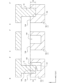
- FIG. 6 is a cross-sectional view taken along lines B-B', C-C', and D-D' in FIG. 5.
- FIG. 7 is a top view illustrating a second step in an example of a method for forming a recess.
- FIG. 8 is a cross-sectional view taken along lines B-B', C-C', and D-D' in FIG. 7.
- FIG. 9 is a top view illustrating a recess formed by the first and second steps.
- FIG. 10 is a top view illustrating a third step in an example of a method for forming a recess.
- FIG. 10 is a top view illustrating a third step in an example of a method for forming a recess.
- FIG. 11 is a cross-sectional view taken along lines B-B', C-C', and D-D' in FIG. 10.
- the top views of FIG. 5, FIG. 7, and FIG. 10 show a state in which a die (punch 10 described later) for forming a recess 720 or an additional recess 730 in the corresponding step is pressed against the first joint 701 of the lead 7, and the triangle indicated by the dotted line shows the shape of the punch 10.
- a first step is performed in which some of the multiple triangular prism-shaped recesses 720 are formed on the upper surface 710 of the first joint 701 of the lead 7.
- the first step as illustrated in Figs. 5 and 6, among the recesses 720 arranged in a hexagonal lattice, only recesses 720 are formed that are adjacent in a positional relationship represented by a primitive translation vector and in which two adjacent equilateral triangles are oriented such that the distance between the parallel sides is shorter than the distance between the corners facing the sides.
- six recesses 720 arranged in a ring shape in a positional relationship represented by a primitive translation vector are formed in a convex direction toward the center of a regular hexagon connecting the formation positions of the six recesses 720, and no recesses 720 are formed in the center of the regular hexagon.
- a punch 10 is used to form a recess 720 having a depth D1.
- the depth D1 is, for example, 100 ⁇ m.
- a second step is performed to form the remaining recesses 720 of the multiple triangular prism-shaped recesses 720 and additional recesses 730 for some of the recesses 720 formed in the first step.
- the second step is performed by shifting the relative positions of the punch 10 used in the first step and the first joint portion 701 of the lead 7 in a plan view by a direction and distance corresponding to the basic translation vector in the U direction.
- some of the punches 10 move to positions where the recesses 720 were not formed in the first step.
- the bottom surface (equilateral triangle) of the recesses 720 formed in the first step is opposite to the bottom surface (equilateral triangle) of the recesses 720. That is, the corners of the bottom surface of the punch 10 that has been moved to the position where the recesses 720 were formed in the first step are positioned outside the recesses 720. Therefore, as shown in FIG.
- the punch 10 used in the first step can form triangular prism-shaped recesses 720 that were not formed in the first step, and additional recesses 730 for some of the triangular prism-shaped recesses 720 formed in the first step. At this time, the bottom surface of the additional recesses 730 is triangular.
- a punch 10 is used to form a recess 720 and an additional recess 730 having a depth D2 shallower than the depth D1.
- the depth D2 is, for example, 50 ⁇ m.
- the triangular prism-shaped recesses 720 without the additional recesses 730 and the recesses 720 with the additional recesses 730 and the return portions 727 are arranged in a hexagonal lattice pattern.
- the recesses 720 with the return portions 727 have a depth D1 as shown in the cross-sectional views of lines B-B' in FIG. 4 and FIG. 8, and have return portions 727 with a protruding amount L1 at a position corresponding to the depth D2 of the additional recesses 730.
- the recesses 720 formed in the first step among the recesses 720 without the return portions 727 have a depth D1 as shown in the cross-sectional views of lines C-C' in FIG. 4 and FIG. 8. Furthermore, the recesses 720 formed in the second step have a depth D2 ( ⁇ D1) as shown in the cross-sectional views of lines D-D' in FIG. 4 and FIG. 8. Furthermore, the bottom surface of the additional recesses 730 is triangular.
- a third step is performed to form additional recesses 730 in the triangular prism-shaped recesses 720 in which the additional recesses 730 were not formed in the second step.
- the third step as illustrated in FIG. 10, the relative positions of the punch 10 and the first joint 701 of the lead 7 used in the first and second steps in a plan view are further shifted by a direction and distance corresponding to the basic translation vector in the U direction.
- the punch 10 moves to the position of the recesses 720 in which the additional recesses 730 were not formed in the second step.
- the bottom surface (equilateral triangle) of the recesses 720 formed in the first step is opposite to the bottom surface (equilateral triangle) of the recesses 720. That is, the corners of the bottom surface of the punch 10 that has been moved to the position where the recess 720 was formed in the first or second step are positioned outside the recess 720. Therefore, the punch 10 used in the first and second steps can form the additional recess 730 in all of the triangular prism-shaped recesses 720 where the additional recess 730 has not been formed.
- a punch 10 is used to form an additional recess 730 having a depth D3 that is shallower than the depth D2.
- the depth D3 is, for example, 25 ⁇ m.
- the method described above with reference to Figures 5 to 11 is merely one example of a method for forming a recess 720 on the upper surface 710 of the first joint portion 701 of the lead 7, the recess 720 having three wall surfaces 721, 722, 723 and a return portion 727 on each of the three wall surfaces 721, 722, 723.
- FIG. 12 is a top view illustrating a conventional example of a recess for preventing peeling at the interface between the first joint of the lead and the sealing material.
- FIG. 13 is a cross-sectional view along line E-E' of the portion shown in FIG. 12.
- FIG. 12 shows a region corresponding to region R in FIG. 1.
- FIG. 13 shows only the portion related to peeling at the interface between the first joint of the lead and the sealing material, and omits the hatching showing the cross section of the coating agent and sealing resin as the sealing material 9.
- the top surface 710 of the first joint portion 701 of the lead 7 illustrated in Figures 12 and 13 has rectangular bottom recesses 740 arranged in a square lattice pattern as recesses to prevent peeling at the interface with the sealing material 9.
- the wall surface of the recess 740 is composed of a wall surface that is approximately parallel to the side (and the opposite side 711) to which the wiring portion 703 is connected on the top surface 710 of the first joint portion 701, and a wall surface that is approximately perpendicular to the side 711. Furthermore, the return portion 727 described above with reference to Figures 3 to 11 is not formed on the wall surface of the recess 740.
- a coating agent 901 that coats the semiconductor element 510 and the lead 7 (first joint portion 701) and a sealing resin 902 that seals the semiconductor element 510 and the lead 7 coated with the coating agent 901 are used as the sealing material 9.
- the coating agent 901 may be, for example, an insulating material such as PA (polyamide).
- the sealing resin 902 may be, for example, an epoxy resin, a silicone gel, etc.
- the difference in thermal expansion coefficient between the coating agent 901 and the joint material S3 is large, and the stress change due to the thermal history of the semiconductor device is large, which may cause peeling.
- the peeling that occurs at the interface between the coating agent 901 and the joint material S3 progresses to the interface between the coating agent 901 and the upper surface 710 of the first joint portion 701 of the lead 7.
- the stress caused by the difference in thermal expansion coefficients, etc. increases in a direction perpendicular to the side of the upper surface 710 of the first bonding portion 701, and the peeling progresses in this direction (in the example of FIG.
- the recess 720 of the present embodiment described above with reference to FIGS. 3 to 11 is a triangular prism, and therefore necessarily has a wall surface that is not perpendicular to the sides of the upper surface 710 of the first joint portion 701 of the lead 7. Therefore, compared to the recess 740 having only wall surfaces perpendicular to one of the sides of the upper surface 710 as illustrated in FIG. 12, peeling is less likely to occur at the interface between the wall surface of the recess 720 and the sealing material 9, and the effect of preventing the peeling from progressing is high.
- the recess 720 of the present embodiment has a return portion 727 that protrudes from the wall surface toward the opposing corner, the part of the sealing material 9 (coating agent 901, etc.) that has entered the recess 720 is less likely to come out of the recess 720. Therefore, in the semiconductor device 1 according to the present embodiment, the effect of preventing the peeling from progressing at the interface between the upper surface 710 of the first joint portion 701 of the lead 7 and the sealing material 9 is high, and the occurrence of failures due to cracks in the sealing material 9 can be prevented.
- the change in the interface between the sealing material 9 and the wall surface of the recess 720 in the direction perpendicular to the side of the top surface 710 of the first joint portion 701 of the lead 7 can be made more complex, and the effect of preventing the progression of peeling at the interface can be further enhanced.
- the method of forming the return portion 727 on the wall surfaces 721, 722, and 723 of the recess 720 is not limited to the method described above with reference to Figures 5 to 11, and may be another method.
- the punch (pressing die) used to form the triangular prism-shaped recess 720 in the first step, the punch used to form the recess 720 and the additional recess 730 in the second step, and the punch used to form the additional recess 730 in the third step may be different punches.
- the recess 720 having the return portion 727 may be formed by, for example, forming the recess 720 of a first depth on the upper surface 710 of the first joint 701 of the lead 7 using a first punch (pressing die), and then forming the additional recess 730 of a second depth shallower than the first depth for all of the recess 720 using a second punch (pressing die).
- a forming method is effective, for example, when the number of triangular prism-shaped recesses 720 formed on the upper surface 710 of the first joint 701 is small.
- the orientation of the bottom surface (equilateral triangle) of the recess 720 may be in a single orientation, or may have a first orientation and a second orientation as described above.
- FIG. 14 is a top view illustrating a second example of a method for forming a return portion on the wall surface of a recess.
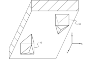
- FIG. 15 is a perspective view illustrating a third example of a method for forming a return portion on the wall surface of a recess.
- FIG. 16 is a cross-sectional view showing an example of a recess and an additional recess formed using the punch illustrated in FIG. 15.
- the method of forming the return portion 727 protruding toward the corners facing each of the wall surfaces 721, 722, and 723 in the triangular prism-shaped recess 720 is not limited to the press processing using the triangular prism-shaped punch 10 described above.
- the additional recess 730 for forming the return portion 727 may be formed by press processing using a punch having a Y-shaped bottom surface 11 in a plan view as shown by the dotted line in FIG. 14.
- the ratio W2/W1 between the side length W1 in a plan view of the triangular prism-shaped recess 720 formed by the punch 10 and the side direction dimension W2 of the recess 720 in the additional recess 730 to be formed can be set to any value. Therefore, for example, by adjusting the ratio W2/W1 and the depth of the additional recess 730, the return portion 727 with the desired protrusion amount L3 can be formed. By adjusting the ratio W2/W1 and the depth of the additional recess 730, the shape of the return portion 727 in a plan view can also be adjusted.
- the area of the return portion 727 in plan view becomes larger (i.e., the path through which the sealant flows from the opening end side of the recess 720 to the bottom surface becomes narrower), preventing the sealant 9 from being insufficiently filled between the return portion 727 and the bottom surface of the recess 720.
- the punch 10 used to form the recess 720 and the additional recess 730 may have a triangular pyramid-shaped convex bottom surface, as shown in FIG. 15.
- the bottom surface of the recess 720 has a triangular pyramid-shaped concave shape, as shown in FIG. 16, so that the contact area between the sealing material 9 and the bottom surface of the recess 720 increases.
- the contact area between the sealing material 9 and the bottom surface of the additional recess 730 increases.
- the protruding direction of the return portion 727 is inclined by an angle ⁇ toward the bottom surface from the direction perpendicular to the wall surfaces 721, 722, and 723, and the return portion 727 is more effective in preventing the sealing material 9 from slipping out of the recess 720.
- the above-mentioned recess 720 has been described as having a bottom shape in a planar view that is an equilateral triangle.
- the shape of the bottom of the recess 720 in a planar view is not limited to an equilateral triangle, and may be another triangular shape.
- the shape of the bottom of the recess 720 in a planar view is not limited to a triangular shape, and may be a polygonal shape having sides that extend in a direction that is not perpendicular to any of the sides of the first joint portion 701 of the lead 7.
- the shape of the bottom of the punch 10 is not limited to the convex triangular pyramid shape described above, and may be another convex shape.
- the recesses 720 having return portions 727 on the wall surface described in the above embodiment may be arranged in a hexagonal lattice pattern over the entire upper surface 710 of the first joint portion 701 of the lead 7, or may not be arranged in a specific area of the upper surface 710. Furthermore, the recesses 720 are not limited to being formed on the upper surface 710 of the first joint portion 701 of the lead 7, and may also be formed on the upper surface of the second joint portion 702, for example.
- the semiconductor device 1 including the semiconductor module 2 of this embodiment can be applied to a power conversion device such as an inverter for an in-vehicle motor.
- a power conversion device such as an inverter for an in-vehicle motor.
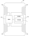
- FIG. 17 is a schematic plan view showing an example of a vehicle to which the semiconductor device according to the present invention is applied.
- the vehicle 2001 shown in FIG. 17 is, for example, a four-wheeled vehicle equipped with four wheels 2002.
- the vehicle 2001 may be, for example, an electric vehicle in which the wheels are driven by a motor or the like, or a hybrid vehicle that uses power from an internal combustion engine in addition to a motor.
- the vehicle 2001 includes a drive unit 2003 that applies power to the wheels 2002, and a control device 2004 that controls the drive unit 2003.
- the drive unit 2003 may be composed of at least one of an engine, a motor, or a hybrid of an engine and a motor, for example.
- the control device 2004 controls (e.g., power control) the drive unit 2003 described above.
- the control device 2004 includes the semiconductor device 1 described above.
- the semiconductor device 1 may be configured to perform power control for the drive unit 2003.
- the semiconductor module 2 of the semiconductor device 1 used in this type of vehicle 2001 if the first joint 701 of the lead 7 described above is joined to the electrode on the top surface of the semiconductor element (e.g., the second main electrode of the semiconductor element 510) with the joining material S3, it is possible to prevent the progression of peeling at the interface between the sealing material 9 and the top surface 710 of the first joint 701. This makes it possible to reduce the frequency of inspection and replacement of the semiconductor device 1 used in the vehicle 2001.
- the semiconductor element e.g., the second main electrode of the semiconductor element 510
- vehicle to which the semiconductor device 1 is applied is not limited to a four-wheeled vehicle as illustrated in FIG. 17.
- Vehicles to which the semiconductor device 1 is applied include railway vehicles, etc.
- the present embodiment is not limited to the above-mentioned embodiment and modifications, and may be modified, substituted, or altered in various ways without departing from the spirit of the technical idea. Furthermore, if the technical idea can be realized in a different way due to technological advances or derived other technologies, it may be implemented using that method. Therefore, the scope of the claims covers all embodiments that may fall within the scope of the technical idea.
- the semiconductor module comprises a circuit board on which a semiconductor element is mounted, leads joined by a bonding material to electrodes on the upper surface of the semiconductor element, and a sealing material that seals the semiconductor element and the leads, and the leads have a plurality of recesses on the upper surface opposite the lower surface facing the electrode at the bonding portion where the leads are bonded to the electrodes, the recesses having a polygonal shape with sides whose bottom surface in a plan view extends in a direction that is not perpendicular to any of the sides of the bonding portion, and each of the plurality of recesses has a return portion that protrudes from the wall surface.
- the recess has a triangular bottom in a plan view, and has an additional recess that extends outward from the wall surface and is shallower than the depth of the recess to the bottom surface, and the return portion protrudes from the wall surface at the position of the bottom surface of the additional recess.
- the recesses are arranged in a hexagonal lattice pattern in a planar view, and include recesses whose triangular bases in a planar view have a first orientation and recesses whose bases have a second orientation opposite to the first orientation.
- the bottom surface of the additional recess is triangular in plan view.
- the multiple recesses include multiple types of recesses having different combinations of the depth to the bottom surface and the depth to the bottom surface of the additional recesses.
- the bottom surface of the additional recess is rectangular in plan view.
- At least one of the bottom surface of the recess and the bottom surface of the additional recess is concave.
- the semiconductor device includes the above semiconductor module and a cooler arranged on the surface of the circuit board of the semiconductor module opposite to the surface on which the semiconductor element is mounted.
- the vehicle according to the above embodiment is equipped with the above semiconductor module or semiconductor device.
- the present invention has the effect of preventing the progression of peeling at the interface between the upper surface of the joint of the lead that is joined to the electrode of the semiconductor element and the sealing material, and is particularly useful for industrial or electrical semiconductor modules, semiconductor devices, and vehicles.
Landscapes
- Structures Or Materials For Encapsulating Or Coating Semiconductor Devices Or Solid State Devices (AREA)
Abstract
Description
Claims (9)
- 半導体素子が搭載された回路板と、
前記半導体素子の上面の電極に接合材により接合されたリードと、
前記半導体素子及び前記リードを封止する封止材と、
を備え、
前記リードは、前記電極に接合される接合部における前記電極と向かい合う下面とは反対側の上面に、平面視での底面が前記接合部の辺のいずれとも直交しない方向に延伸する辺を有する多角形状である複数の凹部を有し、
前記複数の凹部の各々は、壁面から突出する返し部を有する
半導体モジュール。 - 前記凹部は、平面視での底面が三角形状であり、前記壁面から前記凹部の外方に拡張され前記凹部の前記底面までの深さよりも浅い付加凹部を有し、
前記返し部が、前記付加凹部の底面の位置で前記壁面から突出している
請求項1に記載の半導体モジュール。 - 前記凹部は、平面視で六方格子状に配置されており、平面視で三角形状の底面が第1の向きである凹部と、前記第1の向きとは反対の第2の向きである凹部とを含む
請求項2に記載の半導体モジュール。 - 平面視での前記付加凹部の底面が三角形状である
請求項2に記載の半導体モジュール。 - 前記複数の凹部は、前記底面までの深さと前記付加凹部の底面までの深さとの組み合わせが異なる複数種類の凹部を含む
請求項4に記載の半導体モジュール。 - 平面視での前記付加凹部の底面が矩形状である
請求項2に記載の半導体モジュール。 - 前記凹部の底面及び前記付加凹部の底面の少なくとも一方が凹形状である
請求項2に記載の半導体モジュール。 - 請求項1~7のいずれか一項に記載の半導体モジュールと、
前記半導体モジュールの前記回路板における前記半導体素子が搭載された面とは反対側の面に配置された冷却器と、
を備える半導体装置。 - 請求項1~7のいずれか一項に記載の半導体モジュール、又は請求項8に記載の半導体装置を備える車両。
Priority Applications (4)
| Application Number | Priority Date | Filing Date | Title |
|---|---|---|---|
| DE112023002893.1T DE112023002893T5 (de) | 2022-10-06 | 2023-08-31 | Halbleitermodul, halbleitervorrichtung und fahrzeug |
| CN202380031150.6A CN118974916A (zh) | 2022-10-06 | 2023-08-31 | 半导体模块、半导体装置以及车辆 |
| JP2024555668A JP7798206B2 (ja) | 2022-10-06 | 2023-08-31 | 半導体モジュール、半導体装置、及び車両 |
| US18/902,173 US20250022832A1 (en) | 2022-10-06 | 2024-09-30 | Semiconductor module, semiconductor device, and vehicle |
Applications Claiming Priority (2)
| Application Number | Priority Date | Filing Date | Title |
|---|---|---|---|
| JP2022-161588 | 2022-10-06 | ||
| JP2022161588 | 2022-10-06 |
Related Child Applications (1)
| Application Number | Title | Priority Date | Filing Date |
|---|---|---|---|
| US18/902,173 Continuation US20250022832A1 (en) | 2022-10-06 | 2024-09-30 | Semiconductor module, semiconductor device, and vehicle |
Publications (1)
| Publication Number | Publication Date |
|---|---|
| WO2024075445A1 true WO2024075445A1 (ja) | 2024-04-11 |
Family
ID=90607786
Family Applications (1)
| Application Number | Title | Priority Date | Filing Date |
|---|---|---|---|
| PCT/JP2023/031780 Ceased WO2024075445A1 (ja) | 2022-10-06 | 2023-08-31 | 半導体モジュール、半導体装置、及び車両 |
Country Status (5)
| Country | Link |
|---|---|
| US (1) | US20250022832A1 (ja) |
| JP (1) | JP7798206B2 (ja) |
| CN (1) | CN118974916A (ja) |
| DE (1) | DE112023002893T5 (ja) |
| WO (1) | WO2024075445A1 (ja) |
Citations (8)
| Publication number | Priority date | Publication date | Assignee | Title |
|---|---|---|---|---|
| JP2005327767A (ja) * | 2004-05-12 | 2005-11-24 | Dowa Mining Co Ltd | 窪み加工銅板もしくは銅合金板、その製造方法、および順送金型 |
| JP2006510221A (ja) * | 2002-12-13 | 2006-03-23 | フリースケール セミコンダクター インコーポレイテッド | オーバーモールド・プラスチック・パッケージ用ヒートシンクまたはフラグ用の微小モールドロック |
| JP2007258587A (ja) * | 2006-03-24 | 2007-10-04 | Rohm Co Ltd | リードフレームおよびその製造方法並びにリードフレームを備えた半導体装置 |
| JP2007305916A (ja) * | 2006-05-15 | 2007-11-22 | Rohm Co Ltd | リードフレームの製造方法および製造装置 |
| JP2008211168A (ja) * | 2007-01-31 | 2008-09-11 | Mitsubishi Electric Corp | 半導体装置および半導体モジュール |
| JP2017005124A (ja) * | 2015-06-11 | 2017-01-05 | Shマテリアル株式会社 | リードフレーム、リードフレームの製造方法、および半導体装置 |
| JP2017208486A (ja) * | 2016-05-19 | 2017-11-24 | 株式会社ミスズ工業 | 表面に凹凸を有する金属部材、ヒートスプレッダ、半導体パッケージ及びそれらの製造方法 |
| WO2022004758A1 (ja) * | 2020-06-30 | 2022-01-06 | 富士電機株式会社 | 半導体モジュールおよび半導体モジュールの製造方法 |
Family Cites Families (4)
| Publication number | Priority date | Publication date | Assignee | Title |
|---|---|---|---|---|
| JP3753426B2 (ja) | 2003-01-15 | 2006-03-08 | 株式会社東芝 | 超音波接合具および超音波接合具を用いた半導体装置の製造方法 |
| DE102014008587B4 (de) | 2014-06-10 | 2022-01-05 | Vitesco Technologies GmbH | Leistungs-Halbleiterschaltung |
| JP2016018866A (ja) * | 2014-07-08 | 2016-02-01 | 三菱電機株式会社 | パワーモジュール |
| CN107112318B (zh) | 2014-12-29 | 2019-06-18 | 三菱电机株式会社 | 功率模块 |
-
2023
- 2023-08-31 WO PCT/JP2023/031780 patent/WO2024075445A1/ja not_active Ceased
- 2023-08-31 CN CN202380031150.6A patent/CN118974916A/zh active Pending
- 2023-08-31 DE DE112023002893.1T patent/DE112023002893T5/de active Pending
- 2023-08-31 JP JP2024555668A patent/JP7798206B2/ja active Active
-
2024
- 2024-09-30 US US18/902,173 patent/US20250022832A1/en active Pending
Patent Citations (8)
| Publication number | Priority date | Publication date | Assignee | Title |
|---|---|---|---|---|
| JP2006510221A (ja) * | 2002-12-13 | 2006-03-23 | フリースケール セミコンダクター インコーポレイテッド | オーバーモールド・プラスチック・パッケージ用ヒートシンクまたはフラグ用の微小モールドロック |
| JP2005327767A (ja) * | 2004-05-12 | 2005-11-24 | Dowa Mining Co Ltd | 窪み加工銅板もしくは銅合金板、その製造方法、および順送金型 |
| JP2007258587A (ja) * | 2006-03-24 | 2007-10-04 | Rohm Co Ltd | リードフレームおよびその製造方法並びにリードフレームを備えた半導体装置 |
| JP2007305916A (ja) * | 2006-05-15 | 2007-11-22 | Rohm Co Ltd | リードフレームの製造方法および製造装置 |
| JP2008211168A (ja) * | 2007-01-31 | 2008-09-11 | Mitsubishi Electric Corp | 半導体装置および半導体モジュール |
| JP2017005124A (ja) * | 2015-06-11 | 2017-01-05 | Shマテリアル株式会社 | リードフレーム、リードフレームの製造方法、および半導体装置 |
| JP2017208486A (ja) * | 2016-05-19 | 2017-11-24 | 株式会社ミスズ工業 | 表面に凹凸を有する金属部材、ヒートスプレッダ、半導体パッケージ及びそれらの製造方法 |
| WO2022004758A1 (ja) * | 2020-06-30 | 2022-01-06 | 富士電機株式会社 | 半導体モジュールおよび半導体モジュールの製造方法 |
Also Published As
| Publication number | Publication date |
|---|---|
| US20250022832A1 (en) | 2025-01-16 |
| CN118974916A (zh) | 2024-11-15 |
| JP7798206B2 (ja) | 2026-01-14 |
| DE112023002893T5 (de) | 2025-04-17 |
| JPWO2024075445A1 (ja) | 2024-04-11 |
Similar Documents
| Publication | Publication Date | Title |
|---|---|---|
| US10763240B2 (en) | Semiconductor device comprising signal terminals extending from encapsulant | |
| JP7735655B2 (ja) | 半導体装置 | |
| JP7568132B2 (ja) | 半導体モジュール及び半導体装置 | |
| EP3890009A1 (en) | Power module of double-faced cooling with bonding layers including anti-tilting members | |
| JP2023032733A (ja) | 半導体装置 | |
| JP7798206B2 (ja) | 半導体モジュール、半導体装置、及び車両 | |
| US20240145353A1 (en) | Semiconductor module, method for manufacturing semiconductor module, semiconductor device, and vehicle | |
| JP2025138115A (ja) | 半導体モジュール及び車両 | |
| JP7543854B2 (ja) | 半導体装置及び半導体装置の製造方法 | |
| JP7577953B2 (ja) | 半導体装置及び半導体装置の製造方法 | |
| JP7512659B2 (ja) | 半導体モジュール及び半導体モジュールの製造方法 | |
| JP7827161B2 (ja) | 半導体モジュール、半導体装置、及び車両 | |
| JP7106891B2 (ja) | 半導体装置 | |
| JP7147186B2 (ja) | 半導体装置 | |
| US20240136319A1 (en) | Semiconductor module, semiconductor device, and vehicle | |
| JP7845458B2 (ja) | 金属配線板 | |
| JP7681920B2 (ja) | 半導体パッケージ及びその製造方法 | |
| US20240297100A1 (en) | Semiconductor module, semiconductor device, and vehicle | |
| JP7803432B2 (ja) | 半導体モジュール | |
| JP2024072092A (ja) | 半導体モジュール及び半導体装置 | |
| US20250226286A1 (en) | Heat dissipation base, semiconductor module, and energy conversion device | |
| WO2024095710A1 (ja) | 半導体モジュール | |
| WO2024095713A1 (ja) | 半導体モジュール及び半導体モジュールの製造方法 | |
| JP2025014321A (ja) | 半導体装置、及び車両 | |
| WO2024095714A1 (ja) | 半導体モジュール |
Legal Events
| Date | Code | Title | Description |
|---|---|---|---|
| 121 | Ep: the epo has been informed by wipo that ep was designated in this application |
Ref document number: 23874575 Country of ref document: EP Kind code of ref document: A1 |
|
| ENP | Entry into the national phase |
Ref document number: 2024555668 Country of ref document: JP Kind code of ref document: A |
|
| WWE | Wipo information: entry into national phase |
Ref document number: 202380031150.6 Country of ref document: CN |
|
| WWE | Wipo information: entry into national phase |
Ref document number: 112023002893 Country of ref document: DE |
|
| WWP | Wipo information: published in national office |
Ref document number: 112023002893 Country of ref document: DE |
|
| 122 | Ep: pct application non-entry in european phase |
Ref document number: 23874575 Country of ref document: EP Kind code of ref document: A1 |