WO2024075303A1 - Dispositif de détermination de masse de pièce à travailler, dispositif d'estimation d'usinage et système d'usinage - Google Patents
Dispositif de détermination de masse de pièce à travailler, dispositif d'estimation d'usinage et système d'usinage Download PDFInfo
- Publication number
- WO2024075303A1 WO2024075303A1 PCT/JP2022/037724 JP2022037724W WO2024075303A1 WO 2024075303 A1 WO2024075303 A1 WO 2024075303A1 JP 2022037724 W JP2022037724 W JP 2022037724W WO 2024075303 A1 WO2024075303 A1 WO 2024075303A1
- Authority
- WO
- WIPO (PCT)
- Prior art keywords
- workpiece
- machining
- dynamic stiffness
- tool
- grinding
- Prior art date
Links
- 238000003754 machining Methods 0.000 title claims abstract description 197
- 238000003860 storage Methods 0.000 claims abstract description 24
- 238000012545 processing Methods 0.000 claims description 56
- 238000004364 calculation method Methods 0.000 claims description 35
- 238000006073 displacement reaction Methods 0.000 claims description 31
- 239000000463 material Substances 0.000 claims description 30
- 230000002093 peripheral effect Effects 0.000 claims description 30
- 238000012937 correction Methods 0.000 claims description 25
- 230000005284 excitation Effects 0.000 claims description 23
- 238000005457 optimization Methods 0.000 claims description 5
- 238000004458 analytical method Methods 0.000 abstract description 4
- 238000000034 method Methods 0.000 description 26
- 238000010586 diagram Methods 0.000 description 12
- 230000006870 function Effects 0.000 description 11
- 238000004088 simulation Methods 0.000 description 11
- 239000006061 abrasive grain Substances 0.000 description 10
- 238000013016 damping Methods 0.000 description 10
- 238000005520 cutting process Methods 0.000 description 7
- 238000003825 pressing Methods 0.000 description 6
- 230000003068 static effect Effects 0.000 description 6
- 239000011230 binding agent Substances 0.000 description 5
- 238000012888 cubic function Methods 0.000 description 5
- 238000001514 detection method Methods 0.000 description 5
- 238000005259 measurement Methods 0.000 description 5
- 230000000875 corresponding effect Effects 0.000 description 4
- 238000004513 sizing Methods 0.000 description 4
- 230000001276 controlling effect Effects 0.000 description 3
- 230000002706 hydrostatic effect Effects 0.000 description 3
- 239000011148 porous material Substances 0.000 description 3
- 238000012360 testing method Methods 0.000 description 3
- CPLXHLVBOLITMK-UHFFFAOYSA-N Magnesium oxide Chemical compound [Mg]=O CPLXHLVBOLITMK-UHFFFAOYSA-N 0.000 description 2
- 230000000694 effects Effects 0.000 description 2
- BPQQTUXANYXVAA-UHFFFAOYSA-N Orthosilicate Chemical compound [O-][Si]([O-])([O-])[O-] BPQQTUXANYXVAA-UHFFFAOYSA-N 0.000 description 1
- 229920001800 Shellac Polymers 0.000 description 1
- PNEYBMLMFCGWSK-UHFFFAOYSA-N aluminium oxide Inorganic materials [O-2].[O-2].[O-2].[Al+3].[Al+3] PNEYBMLMFCGWSK-UHFFFAOYSA-N 0.000 description 1
- 238000013459 approach Methods 0.000 description 1
- 239000004568 cement Substances 0.000 description 1
- 229910010293 ceramic material Inorganic materials 0.000 description 1
- 239000002131 composite material Substances 0.000 description 1
- 230000002596 correlated effect Effects 0.000 description 1
- 229910003460 diamond Inorganic materials 0.000 description 1
- 239000010432 diamond Substances 0.000 description 1
- 238000009826 distribution Methods 0.000 description 1
- 238000004070 electrodeposition Methods 0.000 description 1
- 238000002474 experimental method Methods 0.000 description 1
- 239000012530 fluid Substances 0.000 description 1
- 238000009434 installation Methods 0.000 description 1
- 238000010801 machine learning Methods 0.000 description 1
- 239000000395 magnesium oxide Substances 0.000 description 1
- 239000000696 magnetic material Substances 0.000 description 1
- 238000004519 manufacturing process Methods 0.000 description 1
- 239000002184 metal Substances 0.000 description 1
- 238000005096 rolling process Methods 0.000 description 1
- ZLGIYFNHBLSMPS-ATJNOEHPSA-N shellac Chemical compound OCCCCCC(O)C(O)CCCCCCCC(O)=O.C1C23[C@H](C(O)=O)CCC2[C@](C)(CO)[C@@H]1C(C(O)=O)=C[C@@H]3O ZLGIYFNHBLSMPS-ATJNOEHPSA-N 0.000 description 1
- 229940113147 shellac Drugs 0.000 description 1
- 235000013874 shellac Nutrition 0.000 description 1
- 239000004208 shellac Substances 0.000 description 1
- HBMJWWWQQXIZIP-UHFFFAOYSA-N silicon carbide Chemical compound [Si+]#[C-] HBMJWWWQQXIZIP-UHFFFAOYSA-N 0.000 description 1
- 229910010271 silicon carbide Inorganic materials 0.000 description 1
Images


Classifications
-
- B—PERFORMING OPERATIONS; TRANSPORTING
- B24—GRINDING; POLISHING
- B24B—MACHINES, DEVICES, OR PROCESSES FOR GRINDING OR POLISHING; DRESSING OR CONDITIONING OF ABRADING SURFACES; FEEDING OF GRINDING, POLISHING, OR LAPPING AGENTS
- B24B49/00—Measuring or gauging equipment for controlling the feed movement of the grinding tool or work; Arrangements of indicating or measuring equipment, e.g. for indicating the start of the grinding operation
- B24B49/16—Measuring or gauging equipment for controlling the feed movement of the grinding tool or work; Arrangements of indicating or measuring equipment, e.g. for indicating the start of the grinding operation taking regard of the load
Definitions
- This disclosure relates to a workpiece material quantity determination device, a machining estimation device, and a machining system.
- the present inventors have previously proposed estimating the machining result with higher accuracy by using dynamic contact stiffness represented by a spring constant K and a damping coefficient C instead of static contact stiffness represented by a spring constant K in the configuration disclosed in Patent Document 1.
- the present inventors then discovered that when the machining result is estimated using dynamic contact stiffness, the dynamic characteristics of the workpiece at the machining point change compared to when not machining, i.e., the analytical workpiece amount changes depending on the machining state, and came up with the idea of a workpiece amount determination device for determining the analytical workpiece amount with high accuracy.
- the present disclosure aims to provide a workpiece material quantity determination device that can analytically determine the workpiece material quantity with high accuracy.
- One aspect of the present disclosure is a workpiece weight determination device that calculates an analytical workpiece weight (M'w(Z')) for analyzing dynamic characteristics during machining in a machining device (2) that machines a workpiece (W) with a tool (T), comprising: a first correspondence relationship storage unit (103b) for storing a mass correspondence relationship between a machining state index (Z') that changes according to a state of machining of the workpiece by the tool and the analytical workpiece mass (M'w(Z')); A processing state index acquisition unit (125) for acquiring the processing state index (Z'); and a workpiece weight determination unit (122) for determining the analytical workpiece weight (M'w(Z')) based on the acquired machining state index (Z') and the mass correspondence relationship.
- a first correspondence relationship storage unit (103b) for storing a mass correspondence relationship between a machining state index (Z') that changes according to a state of machining of the workpiece by the tool and the analytical workpiece mass (M'w(Z'
- the analytical workpiece mass is determined based on the mass correspondence relationship between the stored machining state index and the analytical workpiece mass, and the acquired machining state index. This allows the analytical workpiece mass to be determined with high accuracy based on the correspondence relationship with the machining state index.
- the analytical workpiece material volume determined with high precision in this way can be used, for example, to estimate the machining results of a workpiece together with data on the dynamic contact stiffness between the workpiece and the tool that is exerted by contact between the workpiece and the tool during machining, which is expected to improve the accuracy of estimation of the machining results.
- the above aspect provides a workpiece quantity determination device that can analytically determine the workpiece quantity with high accuracy.
- FIG. 1 is a diagram showing a machining system including a workpiece material amount determination device and a machining estimation device in a first embodiment.
- FIG. 2 is a functional block diagram of a workpiece material amount determination device and a machining estimation device in the first embodiment.
- FIG. 4 is a schematic diagram showing interference between a workpiece and a grinding wheel during grinding.
- FIG. 13 is a diagram showing the shape of a workpiece in a grinding simulation using a group of radial lines, illustrating a state in which the workpiece, represented by the radial lines, interferes with the outer peripheral line of the grinding wheel during grinding.
- 1 is a schematic diagram showing contact dynamic stiffness, workpiece support dynamic stiffness, and tool support dynamic stiffness in grinding.
- FIG. 5A is a diagram showing a first example of a correspondence relationship between a machining state index and contact dynamic stiffness data in the first embodiment
- FIG. 5B is a diagram showing a second example of the correspondence relationship between the machining state index and contact dynamic stiffness data in the first embodiment
- 6A is a diagram showing a third example of a correspondence relationship between a processing state index and contact dynamic stiffness data in the first embodiment
- FIG. 6B is a diagram showing a fourth example of the correspondence relationship between the processing state index and contact dynamic stiffness data in the first embodiment.
- 6 is a flowchart showing a process of acquiring contact dynamic stiffness data for creating a contact dynamic stiffness correspondence relationship.
- 11 is a plan view of the grinding machine when acquiring contact dynamic stiffness for creating a contact dynamic stiffness correspondence relationship.
- 11 is a diagram showing the state of the grinding machine in a part of a process of obtaining contact dynamic stiffness for creating a contact dynamic stiffness correspondence relationship.
- FIG. FIG. 4 is a diagram showing an example of a correspondence relationship between a machining state index and an analytical workpiece mass in the first embodiment.
- 11 is a flowchart showing a process of acquiring the analytical workpiece mass for creating a mass correspondence relationship.
- FIG. 13 shows a machining system including a workpiece material amount determination device and a machining estimation device in a modified embodiment.
- 13 is a schematic diagram showing an interference state between a workpiece, a grinding wheel, and a rest device during grinding in a modified embodiment.
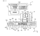
- (Embodiment 1) Configuration of machining system 1
- the workpiece material amount determination device 131, machining estimation device 3b, and machining system 1 in the present embodiment 1 will be described with reference to Fig. 1.
- the machining system 1 is intended for machining devices that perform grinding.
- the machining system 1 includes a grinding machine 2 as a machining device, and a processing unit 3.
- the grinding machine 2 rotates the workpiece W, rotates the grinding wheel T as a tool that is a rotating body, and moves the grinding wheel T relatively close to the workpiece W in a direction that intersects with the axis of the workpiece W, thereby grinding the outer or inner surface of the workpiece W.
- the grinding machine 2 can be a table traverse type grinding machine, a grinding wheel head traverse type grinding machine, or the like.
- the grinding machine 2 can also be a cylindrical grinding machine, a cam grinding machine, or the like.
- the workpiece W has a shaft portion Wa as a non-machined portion, and multiple machined portions Wb whose outer circumferential surfaces are to be ground.
- the machined portions Wb have, for example, a cylindrical outer circumferential surface that is coaxial with the shaft portion Wa.
- the workpiece W shown in FIG. 1 is only one example, and the grinding machine 2 can grind workpieces having various shapes.
- the processing unit 3 includes a control device 3a that controls the grinding machine 2, and a processing estimation device 3b that estimates the processing results.
- the control device 3a controls the grinding machine 2, thereby controlling the grinding process.
- the processing estimation device 3b inputs information used in the grinding process and performs a simulation to estimate the processing results of the workpiece W.
- the processing estimation device 3b can function as a simulation device independent of the grinding machine 2, or as a simulation device that operates in conjunction with the grinding machine 2. In the former case, for example, optimal grinding conditions can be determined without actually grinding the workpiece W. In the latter case, the processing estimation device 3b can, for example, correct the grinding conditions or operate to affect various controls by processing in parallel with the grinding of the workpiece W by the grinding machine 2.
- the processing estimation device 3b can also be an embedded system of the grinding machine 2 and the control device 3a.
- the grinding machine 2 is a table traverse type cylindrical grinding machine.
- the grinding machine 2 is configured to move the workpiece W in the axial direction of the workpiece W and move the grinding wheel T in a direction intersecting the axis of the workpiece W.
- the grinding machine 2 is configured to grind the cylindrical outer peripheral surface of the workpiece W using the grinding wheel T.
- the grinding machine 2 is equipped with a bed 10, a table 20, a spindle device 30, a tailstock device 40, a grinding wheel head 50, a sizing device 60, and a control device 3a.
- the bed 10 is installed on an installation surface.
- the bed 10 is formed so that the width (length in the Z-axis direction) of the front side in the X-axis direction (lower side in Fig. 1) is long, and the width of the back side in the X-axis direction (upper side in Fig. 1) is short.
- the bed 10 has a Z-axis guide surface 11 extending in the Z-axis direction on the upper surface on the front side in the X-axis direction. Furthermore, the bed 10 has a Z-axis drive mechanism 12 that drives along the Z-axis guide surface 11.
- the Z-axis drive mechanism 12 includes a ball screw mechanism 12a and a Z-axis motor 12b.
- the ball screw mechanism 12a extends parallel to the Z-axis guide surface 11, and the Z-axis motor 12b drives the ball screw mechanism 12a.
- a Z-axis drive circuit and a Z-axis detector 12c (not shown) are provided.
- the Z-axis drive circuit includes an amplifier circuit, and drives the Z-axis motor 12b.
- the Z-axis detector 12c is, for example, an angle detector such as an encoder, and detects the angle of the rotation shaft of the Z-axis motor 12b. Note that instead of the configuration including the ball screw mechanism 12a described above, the Z-axis drive mechanism 12 can also use a linear motor or the like.
- the bed 10 also has a guide surface 13 on the upper surface on the rear side in the X-axis direction, which extends in a direction intersecting the Z-axis direction.
- the guide surface 13 is an X-axis guide surface that extends in the X-axis direction perpendicular to the Z-axis.
- the bed 10 also has an X-axis drive mechanism 14 that drives along the X-axis guide surface 13.
- the X-axis drive mechanism 14 includes a ball screw mechanism 14a and an X-axis motor 14b.
- the ball screw mechanism 14a extends parallel to the X-axis guide surface 13, and the X-axis motor 14b drives the ball screw mechanism 14a.
- an X-axis drive circuit and an X-axis detector 14c (not shown) are provided.
- the X-axis drive circuit includes an amplifier circuit, and drives the X-axis motor 14b.
- the X-axis detector 14c is, for example, an angle detector such as an encoder, and detects the angle of the rotation shaft of the X-axis motor 14b.
- the X-axis drive mechanism 14 can also use a linear motor or the like instead of the configuration including the ball screw mechanism 14a described above.
- the table 20 is formed in an elongated shape and is supported on the Z-axis guide surface 11 of the bed 10 so as to be movable in the Z-axis direction (horizontal left and right direction).
- the table 20 is also fixed to the ball screw nut of the Z-axis ball screw mechanism 12a, and moves in the Z-axis direction by the rotational drive of the Z-axis motor 12b.
- the spindle device 30 constitutes a workpiece support device.
- the spindle device 30 supports the workpiece W and drives it to rotate.
- the spindle device 30 is disposed on one end side of the table 20 in the Z-axis direction.
- the spindle device 30 includes a spindle housing 31, a spindle 32, a spindle motor 33, a spindle center 34, a spindle detector 35, and a spindle drive circuit (not shown).
- the spindle housing 31 is fixed on the table 20.
- the spindle 32 is rotatably supported by the spindle housing 31 via a bearing.
- the spindle motor 33 drives the spindle 32 to rotate.
- the spindle center 34 supports one axial end face of the workpiece W.
- the spindle center 34 is fixed to the spindle 32 and is rotatable relative to the spindle housing 31.
- the spindle device 30 is equipped with a rotating member such as a chuck (not shown)
- the spindle center 34 may be fixed to the spindle housing 31 and installed so as to be unable to rotate relative to the spindle housing 31.
- the spindle device 30 may also be equipped with a chuck for gripping the workpiece W instead of the spindle center 34.
- the chuck is driven to rotate by being connected to the spindle 32.
- the spindle detector 35 and the spindle drive circuit are provided to drive the spindle motor 33.
- the spindle detector 35 is, for example, an angle detector such as an encoder, and detects the angle of the rotation shaft of the spindle motor 33.
- the spindle drive circuit includes an amplifier circuit, and drives the spindle motor 33.
- the tailstock device 40 together with the spindle device 30, constitutes a workpiece support device.
- the tailstock device 40 is disposed on the other end side of the table 20 in the Z-axis direction.
- the tailstock device 40 is provided so as to be movable in the Z-axis direction on the table 20.
- the tailstock device 40 includes a tailstock center 41.
- the tailstock center 41 supports the end face of the other axial end of the workpiece W.
- the tailstock center 41 may be provided so as not to rotate, or so as to be rotatable. Note that when the grinding machine 2 grinds the inner peripheral surface of the workpiece W, the tailstock device 40 is not necessary.
- the tailstock center 41 may be positioned at a fixed position relative to the workpiece W, or may be provided so as to be movable in the axial direction of the workpiece W relative to the workpiece W. In the latter case, the tailstock center 41 may be configured so that the pressing force in the axial direction of the workpiece W can be adjusted relative to the workpiece W.
- the pressing force can be controlled by a means for adjusting the spring force, a means for adjusting the fluid pressure, or the like.
- the grinding wheel head 50 is equipped with a grinding wheel T as a tool, and rotates and drives the grinding wheel T.
- the grinding wheel head 50 is equipped with a grinding wheel head body 51, a grinding wheel spindle 52, a grinding wheel motor 53, and a grinding wheel drive circuit (not shown).
- the grinding wheel T is formed in a disk shape.
- the grinding wheel T is used to grind the outer or inner surface of the workpiece W.
- the grinding wheel T is composed of multiple abrasive grains fixed with a binder.
- the abrasive grains used include general abrasive grains made of ceramic materials such as alumina and silicon carbide, and super abrasive grains such as diamond and CBN.
- Binders include vitrified (V), resinoid (B), rubber (R), silicate (S), shellac (E), metal (M), electrochemical deposition (P), and magnesia cement (Mg).
- grinding wheels T are available in configurations with and without pores. Depending on the type of binder and the presence or absence of pores, grinding wheels T may be elastically deformable or almost non-elastically deformable. In elastically deformable grinding wheels T, the elastic modulus differs depending on the type of binder, the presence or absence of pores, the porosity, etc.
- the wheel head body 51 is formed, for example, in a rectangular shape when viewed from above, and is supported on the X-axis guide surface 13 of the bed 10 so as to be movable in the X-axis direction (horizontal front-back direction).
- the wheel head body 51 is also fixed to the ball screw nut of the X-axis ball screw mechanism 14a, and moves in the X-axis direction by the rotational drive of the X-axis motor 14b.
- the wheel head body 51 constitutes a tool support device that supports the grinding wheel T.
- the grinding wheel spindle 52 is rotatably supported on the grinding wheel head body 51 via bearings.
- a grinding wheel T is fixed to the tip of the grinding wheel spindle 52, and the grinding wheel T rotates as the grinding wheel spindle 52 rotates.
- a grinding wheel motor 53 drives the grinding wheel spindle 52 to rotate.
- the bearings used may be hydrostatic bearings or rolling bearings.
- the grinding wheel motor 53 transmits the rotational driving force to the grinding wheel spindle 52, for example, via a belt. However, the grinding wheel motor 53 may be arranged coaxially with the grinding wheel spindle 52. In general, the rotation speed of the grinding wheel T driven by the grinding wheel motor 53 is faster than the rotation speed of the workpiece W driven by the spindle motor 33.
- the grinding wheel drive circuit is provided to drive the grinding wheel motor 53.
- the grinding wheel drive circuit includes an amplifier circuit, and drives the grinding wheel motor 53.
- the sizing device 60 is provided on the upper surface of the bed 10 and measures the outer diameter of the workpiece W.
- the sizing device 60 is equipped with, for example, a pair of contacts that can contact the outer peripheral surface of the workpiece W, and measures the outer diameter at the point of contact with the workpiece W.
- the control device 3a is a CNC (Computer Numerical Control) device and a PLC (Programmable Logic Controller) device that executes processing control. That is, based on the grinding program and the measurement results by the sizing device 60, the control device 3a drives the Z-axis drive mechanism 12 and the X-axis drive mechanism 14 as moving devices to control the positions of the table 20 and the grinding wheel head 50. That is, the control device 3a controls the positions of the table 20 and the grinding wheel head 50, etc., thereby moving the workpiece W and the grinding wheel T closer to and farther apart relative to each other. Furthermore, the control device 3a controls the spindle device 30 and the grinding wheel head 50. That is, the control device 3a controls the rotation of the spindle 32 and the grinding wheel T.
- CNC Computer Numerical Control
- PLC Programmable Logic Controller
- the machining estimation device 3b includes a command value acquisition unit 101, an estimation unit 102, a contact dynamic stiffness table storage unit (second correspondence relationship storage unit) 103a, a workpiece material mass table storage unit (first correspondence relationship storage unit) 103b, a workpiece support dynamic stiffness table storage unit 103c, a tool support dynamic stiffness table storage unit 103d, a machining condition acquisition unit 106, a dynamic characteristic determination unit 107, a correction amount calculation unit 108, an output unit 109, and a machining condition optimization unit 110.
- the command value acquisition unit 101 acquires command values for controlling the grinding machine 2 during grinding.
- the processing estimation device 3b is a simulation device independent of the grinding machine 2
- the command value acquisition unit 101 inputs a grinding program and configuration information of the grinding machine 2 to generate command values for controlling each part of the grinding machine 2 through calculations.
- the processing estimation device 3b functions as a simulation device that operates in conjunction with the grinding process performed by the grinding machine 2
- the command value acquisition unit 101 can acquire command values directly from the control device 3a of the grinding machine 2.
- the estimation unit 102 executes a grinding simulation using the command values acquired by the command value acquisition unit 101 to estimate at least one of the state of the workpiece W or the grinding wheel T during grinding, the shape of the workpiece W, the shape of the grinding wheel T, and the mechanical state of the grinding machine 2.
- the state of the workpiece W includes, for example, the vibration state and temperature state of the workpiece W.
- the state of the grinding wheel T includes, for example, the vibration state and temperature state of the grinding wheel T, the grinding resistance generated at each part of the outer surface of the grinding wheel T, the sharpness of the grinding wheel T, and the state of the abrasive grains that make up the grinding wheel T.
- the state of the abrasive grains includes, for example, the average protrusion amount of the abrasive grains and the abrasive grain distribution.
- the shape of the workpiece W includes the shape at an intermediate stage of the grinding process and the shape at the end of the grinding process.
- the shape of the grinding wheel T includes the shape at an intermediate stage of the grinding process and the shape at the end of the grinding process.
- the mechanical state of the grinding machine 2 includes the vibration state and temperature state of the parts that make up the grinding machine 2.
- the estimation unit 102 performs a process in which the shape of the workpiece W changes sequentially through a grinding simulation, and estimates the shape of the workpiece W, the state of the workpiece W, and the mechanical state of the grinding machine 2 as the estimation targets.
- the grinding simulation is performed assuming that the grinding wheel T does not deform.
- the estimation unit 102 can also estimate the grinding resistance generated at each part of the outer circumferential surface of the grinding wheel T.
- the estimation unit 102 includes an interference amount calculation unit 111, a grinding efficiency calculation unit 112, a grinding characteristic determination unit 113, and a grinding resistance calculation unit 114.
- the interference amount calculation unit 111 calculates the amount of interference between the workpiece W and the grinding wheel T based on the relative positions of the workpiece W and the grinding wheel T, the outer peripheral surface shape of the workpiece W, and the outer peripheral surface shape of the grinding wheel T obtained using the command values acquired by the command value acquisition unit 101.
- the amount of interference corresponds to the amount of radial grinding of the workpiece W at each circumferential portion of the workpiece W.
- the amount of interference is the amount of removal of the workpiece W ground by the grinding wheel T, more specifically, the amount of radial removal of the workpiece W at each circumferential portion of the workpiece W.
- the amount of interference is the volume of the portion where the workpiece W interferes with the grinding wheel T (the shaded portion in FIG. 3: the interference area).
- the interference amount calculation unit 111 calculates the amount of interference geometrically by arithmetic processing.
- the interference amount calculation unit 111 stores the outer peripheral surface shape of the workpiece W and the outer peripheral surface shape of the grinding wheel T.
- the outer peripheral surface shape of the workpiece W is expressed by a group of multiple radial line segments on a polar coordinate system with the rotation center Ow of the workpiece W as the origin.
- the interference amount calculation unit 111 stores a group of multiple line segments connecting the division points (white points in FIG. 4) on the outer peripheral surface obtained by dividing the workpiece W equiangularly ( ⁇ ) and the rotation center Ow (origin) of the workpiece W as the outer peripheral surface shape of the workpiece W.
- the division points shown by white points in FIG. 4 are stored as the outer peripheral surface shape of the workpiece W before it is removed by the grinding wheel T.
- the interference amount calculation unit 111 determines the intersections (black dots in FIG. 4) between each line segment of the workpiece W and the line representing the outer peripheral shape of the grinding wheel T from the relative position (center distance) between the workpiece W and the grinding wheel T and the outer peripheral shape of the grinding wheel T.
- the interference amount calculation unit 111 stores the determined intersections (black dots in FIG. 4) as the outer peripheral shape of the workpiece W after it has been removed by the grinding wheel T. In other words, the interference amount calculation unit 111 changes the stored outer peripheral shape of the workpiece W.
- the interference amount calculation unit 111 subtracts the area of the triangle ⁇ Ow-b1-b2 consisting of the points b1 and b2 (intersection with the grinding wheel T) after removal and the origin Ow from the area of the triangle ⁇ Ow-a1-a2 consisting of the origin Ow and adjacent points a1 and a2 among the points that define the outer peripheral surface shape of the workpiece W before removal.
- the areas after subtraction are calculated for all adjacent points that define the outer peripheral surface shape of the workpiece W.
- the interference amount calculation unit 111 adds up the areas after each subtraction and multiplies the total area thus added up by the thickness of the workpiece W to calculate the amount of interference (amount of removal).
- the area of the portion to be removed is calculated by calculating the areas of the two types of triangles and then calculating the difference between these areas.
- the area of the portion to be removed may be calculated by directly calculating the quadrangle a1-a2-b1-b2.
- the grinding efficiency calculation unit 112 calculates the grinding efficiency (processing efficiency) Z' based on the amount of interference calculated by the interference amount calculation unit 111.
- the grinding efficiency Z' calculates the amount of interference per unit time, i.e., the volume of the workpiece W ground by the grinding wheel T in unit time.
- the grinding characteristic determination unit 113 determines the grinding characteristic kc based on the material of the workpiece W, the type of abrasive grains and binder of the grinding wheel T, and the condition of the outer peripheral surface of the grinding wheel T.
- the condition of the outer peripheral surface of the grinding wheel T is expressed, for example, using an index that indicates the wear state and sharpness of the abrasive grains of the grinding wheel T.
- the grinding characteristic determination unit 113 stores the grinding characteristics in each state in advance through experiments, analysis, etc.
- the grinding resistance calculation unit 114 calculates the grinding resistance Fn in the normal direction (X-axis direction) of the outer peripheral surface of the workpiece W based on the grinding efficiency Z' and the grinding characteristic kc.
- the grinding characteristic kc has a nearly linear relationship such that the grinding resistance Fn in the normal direction (X-axis direction) increases as the grinding efficiency Z' increases.
- the grinding characteristic kc changes this relationship, for example, when the grinding wheel T is worn. For example, when the grinding wheel T is worn, the grinding resistance Fn in the normal direction changes to increase with respect to the grinding efficiency Z'.
- the contact dynamic stiffness table memory unit 103a stores contact dynamic stiffness data (Ci(Z'), Ki(Z')) between the workpiece W and the grinding wheel T.
- the contact dynamic stiffness table memory unit 103a constitutes a second correspondence relationship memory unit 103a that stores the correspondence between the machining state index described below and the contact dynamic stiffness data (Ci(Z'), Ki(Z')).
- the workpiece support dynamic stiffness table memory unit 103c stores workpiece support dynamic stiffness data (Cw, Kw) in the spindle unit 30 and tailstock unit 40 as workpiece support devices.
- the workpiece support dynamic stiffness table memory unit 103c stores the correspondence between the machining conditions and the workpiece support dynamic stiffness data (Cw, Kw).
- the tool support dynamic stiffness table memory unit 103d stores tool support dynamic stiffness data (Ct, Kt) in the wheel head body 51 as a grinding wheel support device.
- the tool support dynamic stiffness table storage unit 103d stores the correspondence between the machining conditions and the tool support dynamic stiffness data (Ct, Kt).
- the machining condition acquisition unit 106 acquires the machining conditions when performing grinding by the grinding machine 2.
- the machining condition acquisition unit 106 acquires the machining conditions at the time of estimation by the estimation unit 102 (at the time of processing).
- the machining conditions acquired by the machining condition acquisition unit 106 are information used by the dynamic characteristic determination unit 107 to calculate each dynamic stiffness.
- the acquired machining conditions are, for example, the type of workpiece W, the type of workpiece support member, the type of grinding wheel T, and the pressing forces by the spindle center 34 and the tailstock center 41.
- the processing condition acquisition unit 106 acquires the conditions for determining the dynamic stiffness by inputting the mechanical configuration and grinding program of the grinding machine 2. Also, if the processing estimation device 3b functions as a simulation device that operates in conjunction with the grinding process by the grinding machine 2, the processing condition acquisition unit 106 may acquire the conditions for determining the dynamic stiffness by inputting the mechanical configuration and grinding program of the grinding machine 2 from the control device 3a, or may acquire information regarding the conditions directly from the control device 3a of the grinding machine 2.
- the dynamic characteristic determining unit 107 determines dynamic stiffness data and analytical workpiece mass (M'w(Z')) that affect grinding.
- the dynamic characteristic determining unit 107 separately determines the contact dynamic stiffness data (Ci(Z'), Ki(Z')), workpiece support dynamic stiffness data (Cw, Kw), tool support dynamic stiffness data (Ct, Kt), and analytical workpiece mass (M'w(Z')) shown in FIG. 5. That is, the dynamic characteristic determining unit 107 includes a contact dynamic stiffness determining unit 121, a workpiece mass determining unit 122, a workpiece support dynamic stiffness determining unit 123, and a tool support dynamic stiffness determining unit 124.
- the contact dynamic stiffness (Ci(Z'), Ki(Z')), workpiece support dynamic stiffness (Cw, Kw), tool support dynamic stiffness (Ct, Kt) and workpiece mass (Mw) will be explained with reference to FIG. 5.
- the contact dynamic stiffness (Ci(Z'), Ki(Z')) is the dynamic stiffness between the workpiece W and the grinding wheel T.
- the workpiece support dynamic stiffness (Cw, Kw) includes the workpiece W and is the dynamic stiffness of the workpiece W side relative to the table 20, spindle unit 30 and unit 40.
- the tool support dynamic stiffness (Ct, Kt) includes the grinding wheel T and is the dynamic stiffness relative to the wheel head 50.
- the workpiece mass (Mw) is the mass of the workpiece W.
- Contact dynamic stiffness is the dynamic stiffness between the workpiece W and the grinding wheel T, and is the dynamic stiffness exhibited by the contact between the workpiece W and the grinding wheel T during grinding.
- Contact dynamic stiffness is defined by a damping coefficient Ci and a spring constant Ki.
- contact static stiffness which is distinguished from contact dynamic stiffness, is represented only by the spring constant K and does not include the damping coefficient C.
- the damping coefficient Ci in contact dynamic stiffness is a value that represents the relationship between the relative speed between the workpiece W and the grinding wheel T and the external force that the workpiece W or the grinding wheel T receives.
- the spring constant Ki is a value that represents the relationship between the relative position between the workpiece W and the grinding wheel T and the external force that the workpiece W or the grinding wheel T receives.
- the contact dynamic stiffness corresponds to a processing condition index that changes according to the state of processing of the workpiece W by the tool (grinding wheel T) in the processing device 2 during grinding.
- the processing condition index include processing efficiency (grinding efficiency Z'), contact arc length L, and g/a (grain cutting depth/grain cutting edge interval).
- the contact dynamic stiffness correspondence relationship which is the correspondence relationship between the processing condition index and the contact dynamic stiffness data (Ci(Z'), Ki(Z')), can be obtained by performing actual measurement.
- the contact arc length L is the arc length of the outer circumferential surface of the grinding wheel T that is in contact with the workpiece W during grinding, in a cross section perpendicular to the axis of the grinding wheel T, as shown in FIG. 3.
- the contact arc length L changes depending on the feed speed of the grinding wheel T in the X-axis direction, the outer diameter of the grinding wheel T, the outer diameter of the workpiece W, etc.
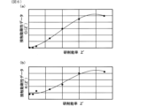
- FIGs. 6(a) and (b) and 7(a) and (b) show examples of the contact dynamic stiffness correspondence relationship between the machining state index and the contact dynamic stiffness data (Ci(Z'), Ki(Z')).
- the grinding efficiency Z' is used as the machining state index
- the damping coefficient Ci and the spring constant Ki in the contact dynamic stiffness have a nonlinear relationship with respect to the grinding efficiency Z', not a linear relationship (proportional relationship).
- the contact dynamic stiffness correspondence relationship between the machining state index and the contact dynamic stiffness data (Ci(Z'), Ki(Z')) is a relationship in which the degree of change of the contact dynamic stiffness data (Ci(Z'), Ki(Z')) with respect to the machining state index varies.
- a function representing a curve whose slope changes continuously can be specified as an approximate formula.
- the approximation formula can be a higher-order function; for example, the curves shown in Figures 6(a) and (b) are curves defined by cubic functions.
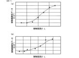
- the contact arc length L is used as the machining state index.
- the machining state index shows a tendency similar to that when the grinding efficiency Z' is used, but it tends to be difficult to fit the curve represented by a cubic function compared to when the machining state index is the grinding efficiency Z'.
- the machining state index is the grinding efficiency as shown in Figures 6(a) and (b)
- the correspondence relationship between the machining state index and the contact dynamic stiffness data shows a tendency similar to that in the case of the grinding efficiency Z' shown in Figures 6(a) and (b).
- the contact dynamic stiffness correspondence relationship may be a combination of multiple straight lines on the quadratic plane instead of the curve.
- the contact dynamic stiffness correspondence relationship may be in the form of a data table consisting of multiple data correspondence relationships instead of being specified as a function such as an approximation equation.
- the machining state index is acquired by the machining state index acquisition unit 125 provided in the contact dynamic stiffness determination unit 121, and the contact dynamic stiffness correspondence, which is the correspondence between the machining state index and the contact dynamic stiffness data (Ci(Z'), Ki(Z')), is stored in the second correspondence storage unit 103a.
- the contact dynamic stiffness data (Ci(Z'), Ki(Z')) is determined by the contact dynamic stiffness determination unit 121 based on the machining state index acquired by the machining state index acquisition unit 125.
- the machining state index acquisition unit 125, the second correspondence storage unit 103a, and the contact dynamic stiffness determination unit 121 constitute the contact dynamic stiffness determination device 130.
- the measuring jig 4 is attached to the grinding machine 2 and the workpiece W (S1).
- the measuring jig 4 is a non-contact vibrator, and is a device that applies a vibration force to the workpiece W.
- the measuring jig 4 is provided on the upper surface of the table 20. The fixed position of the measuring jig 4 in the Z-axis direction on the upper surface of the table 20 is adjustable.
- the measuring jig 4 holds the workpiece W with the workpiece W inserted therethrough.
- a part of the shaft portion Wa which is the non-machined portion of the workpiece W, is inserted into the measuring jig 4, and multiple machined portions Wb to be ground are located outside the measuring jig 4.
- the workpiece W inserted and held in the measuring jig 4 is supported by the spindle device 30 and tailstock device 40, in the same way as during normal grinding.
- the measuring jig 4 includes a housing 131, an electromagnet 132, a rotor 133, a lock nut 134, a displacement sensor 135, and a control device 136.
- the housing 131 is fixed to the upper surface of the table 20 of the grinding machine 2. Furthermore, the housing 131 is formed with a hole 131a that penetrates in the Z-axis direction.
- the electromagnet 132 is embedded in the housing 131.
- the rotor 133 is attached to the outer circumferential surface of the workpiece W and is provided integrally with the workpiece W.
- the rotor 133 is made of a magnetic material and moves due to the magnetic force generated by the electromagnet 132.
- the rotor 133 is formed in a cylindrical shape, and the outer circumferential surface of the rotor 133 is disposed with a predetermined gap from the inner circumferential surface of the housing 131. This gap is the distance that the rotor 133 can move relative to the housing 131.
- the inner circumferential surface of the rotor 133 is formed according to the shape of the outer circumferential surface of the workpiece W.
- the lock nut 134 is a member for fixing the rotor 133 to the workpiece W. The method of fixing the rotor 133 is not limited to the means using the lock nut 134, and various means can be adopted.
- the displacement sensor 135 is provided at a position close to the inner circumferential surface of the housing 131, and measures the distance to the outer circumferential surface of the rotor 133. In other words, when the rotor 133 is vibrated by the electromagnet 132, the displacement sensor 135 measures the displacement of the rotor 133 in the direction in which the rotor 133 approaches or moves away from the inner circumferential surface of the housing 131 (hereinafter referred to as radial displacement).
- the control device 136 supplies a drive current to the electromagnet 132 so that the electromagnet 132 applies a vibration force.
- the control device 136 also acquires the displacement measured by the displacement sensor 135, i.e., the radial displacement of the rotor 133.
- the housing 131 of the measuring jig 4 is attached to the table 20. Furthermore, the workpiece W to which the rotor 133 is attached is supported by the spindle device 30 and the tailstock device 40. At this time, the position of the housing 131 is adjusted so that the outer circumferential surface of the rotor 133 faces the inner circumferential surface of the housing 131 of the measuring jig 4, as shown in FIG. 10(b).
- grinding is started (S2). That is, while the workpiece W and the grinding wheel T are rotating, the grinding wheel T is moved in the X-axis direction to grind the outer peripheral surface of the processed portion Wb of the workpiece W.
- an excitation force is applied by the measuring jig 4 (S3).
- the excitation force is applied by the measuring jig 4 while the workpiece W is being ground by the grinding wheel T.
- the excitation force applied may be impulse excitation or sweep excitation in which the excitation frequency is changed continuously.
- the excitation force is applied by the control device 136 of the measuring jig 4 supplying a current to the electromagnet 132.
- the excitation force is controlled by the current supplied to the electromagnet 132 by the control device 136.
- the displacement sensor 135 of the measuring jig 4 measures the radial displacement that occurs in the workpiece W when an excitation force is applied to the workpiece W.
- the overall dynamic stiffness data (Ccom, Kcom) during grinding is calculated (S6).
- the overall dynamic stiffness data (Ccom, Kcom) is the overall (composite) dynamic stiffness data represented by the above-mentioned contact dynamic stiffness data (Ci(Z'), Ki(Z')), workpiece support dynamic stiffness data (Cw, Kw), and tool support dynamic stiffness data (Ct, Kt).
- the overall dynamic stiffness data (Ccom, Kcom) is represented as the sum of the above-mentioned contact dynamic stiffness data (Ci(Z'), Ki(Z')), workpiece support dynamic stiffness data (Cw, Kw), and tool support dynamic stiffness data (Ct, Kt).
- the radial displacement measured by the displacement sensor 135 of the measuring jig 4 is measured when an excitation force is applied to the workpiece W during grinding. Therefore, the measured displacement is affected by the contact dynamic stiffness data (Ci(Z'), Ki(Z')), workpiece support dynamic stiffness data (Cw, Kw), and tool support dynamic stiffness data (Ct, Kt).
- the calculation of the overall dynamic stiffness data (Ccom, Kcom) is data generated from the relationship between the excitation force and the radial displacement of the workpiece W when an excitation force is applied to the workpiece W during grinding.
- the workpiece support dynamic stiffness data (Cw, Kw) and the tool support dynamic stiffness data (Ct, Kt) are acquired (S7).
- the workpiece support dynamic stiffness data (Cw, Kw) and the tool support dynamic stiffness data (Ct, Kt) are acquired in advance by a hammering test or the like.
- the contact dynamic stiffness data (Ci(Z'), Ki(Z')) is calculated (S8).
- the contact dynamic stiffness data (Ci(Z'), Ki(Z')) is obtained by subtracting the workpiece support dynamic stiffness data (Cw, Kw) and the tool support dynamic stiffness data (Ct, Kt) from the overall dynamic stiffness data (Ccom, Kcom).
- the interpolation process is a process in which the contact dynamic stiffness data (Ci, Ki) obtained by actual measurement is used to obtain contact dynamic stiffness data (Ci(Z'), Ki(Z')) under grinding conditions different from the actual measurement.
- an empirical formula that defines the relationship between the contact arc length L, the damping coefficient Ci, and the spring constant Ki can be used.
- the interpolation process can also apply an empirical formula, machine learning, theoretical calculation, etc. In this way, the contact dynamic stiffness correspondence relationship with the processing condition index (grinding efficiency) shown in Figures 6(a) and (b) can be created using the contact dynamic stiffness data (Ci(Z'), Ki(Z')).
- the workpiece support dynamic stiffness is the dynamic stiffness related to support in the spindle unit 30 and tailstock unit 40 shown in FIG. 1, and is the dynamic stiffness exhibited when the workpiece W is supported by the spindle unit 30 and tailstock unit 40 as the workpiece support devices constituting the grinding machine 2.
- the workpiece support dynamic stiffness is defined by a damping coefficient Cw and a spring constant Kw.
- the damping coefficient Cw is a value that represents the relationship between the relative speed of the workpiece W with respect to the reference positions of the spindle unit 30 and tailstock unit 40, and the external force that the workpiece W receives.
- the spring constant Kw is a value that represents the relationship between the relative position of the workpiece W with respect to the reference positions of the spindle unit 30 and tailstock unit 40, and the external force that the workpiece W receives.
- the workpiece support dynamic stiffness data (Cw, Kw) is stored in the workpiece support dynamic stiffness table storage unit 103c so as to correspond to the above-mentioned machining conditions.
- the workpiece support dynamic stiffness data (Cw, Kw) is data that changes as the contact state between the tailstock center 41 and the workpiece W changes due to a change in the pressing force by the tailstock center 41.
- the workpiece support dynamic stiffness data (Cw, Kw) can be obtained, for example, by performing a hammering test while changing the pressing force by the tailstock center 41 in a state in which the workpiece W is supported by the spindle center 34 and the tailstock center 41.
- the workpiece support dynamic stiffness determination unit 123 determines the workpiece support dynamic stiffness data (Cw, Kw) corresponding to the machining conditions acquired by the machining condition acquisition unit 106 from the workpiece support dynamic stiffness table stored in the workpiece support dynamic stiffness table storage unit 103c.
- the analytical workpiece weight (M'w(Z')) is the analytical mass of the workpiece W, and is a value correlated with the machining state index.
- a mass correspondence relationship, which is a correspondence relationship between the analytical workpiece weight (M'w(Z')) and the machining state index, is stored in the workpiece weight table storage unit 103b, which serves as a first correspondence relationship storage unit.
- the machining state index in the mass correspondence relationship can be the same as in the case of the contact dynamic stiffness correspondence relationship described above.
- the mass correspondence relationship between the machining state index and the analytical workpiece mass (M'w(Z')) shows an example of the mass correspondence relationship between the machining state index and the analytical workpiece mass (M'w(Z')).
- the analytical workpiece mass (M'w(Z')) has a nonlinear relationship, not a linear relationship (proportional relationship), with respect to the grinding efficiency Z' as the machining state index.
- the mass correspondence relationship between the machining state index and the analytical workpiece mass (M'w(Z')) is a relationship in which the degree of change of the analytical workpiece mass (M'w(Z')) with respect to the machining state index varies.
- a function representing a curve whose slope changes continuously can be specified as an approximation formula.
- the approximation formula can be a higher-order function, and for example, the curve shown in FIG. 11 is a curve specified by a cubic function.
- the mass correspondence relationship may be a curve in which a plurality of straight lines are connected in the quadratic plane instead of the curve.
- the mass correspondence may be in the form of a data table consisting of correspondences between multiple pieces of data.
- Figure 11 shows the case where the machining condition index is the grinding efficiency Z', but even when the machining condition index is the contact arc length L or g/a, the mass correspondence relationship between the machining condition index and the analytical workpiece mass (M'w(Z')) shows roughly the same tendency as in the case of grinding efficiency Z' shown in Figure 11, but it is preferable to use grinding efficiency Z' as the machining condition index, just as in the case of the contact dynamic stiffness correspondence relationship.
- the machining state index is acquired by the machining state index acquisition unit 125, and the mass correspondence, which is the correspondence between the machining state index and the analytical workpiece amount (M'w(Z')), is stored in the first correspondence storage unit 103b.
- the analytical workpiece amount (M'w(Z')) is then determined by the workpiece amount determination unit 122 based on the machining state index acquired by the machining state index acquisition unit 125.
- the machining state index acquisition unit 125, the first correspondence storage unit 103b, and the workpiece amount determination unit 122 constitute the workpiece amount determination device 131.
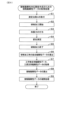
- Analytical workpiece mass acquisition process for creating mass correspondence relationship The analytical workpiece mass (M'w(Z')) in the mass correspondence relationship is created based on the workpiece dynamic characteristics (Mw, Cw, Kw) during non-machining and the contact dynamic stiffness data (Ci(Z'), Ki(Z')).
- the workpiece mass acquisition process for creating the mass correspondence relationship will be described below with reference to the flow chart shown in FIG. 12.
- step S11 shown in FIG. 12 the vibration device 4 is used to measure the dynamic characteristics during machining at the detection position We of the displacement sensor 135 in each of the multiple states in which the grinding efficiency Z' is changed according to the process shown in FIG. 8. At this time, since the grinding efficiency Z' is changed, the grinding resistance changes in correlation with the grinding efficiency Z', and therefore the grinding resistance can be expressed as Fn(Z').
- step S12 the dynamic characteristics (Mw, Cw, Kw) during non-machining at the detection position We of the displacement sensor 135 are analyzed.
- the dynamic characteristics are set as initial dynamic characteristics (initial masses Mw, Cw, Kw) using, for example, actual measured values from a hammering test during non-machining.
- step S13 the contact dynamic stiffness data (Ci(Z'), Ki(Z')) is identified so that the dynamic characteristics (initial masses Mw, Cw, Kw) during non-machining at the detection position We of the displacement sensor 135 match the dynamic characteristics during machining of each of the multiple grinding efficiencies Z' at the detection position We of the displacement sensor 135.
- step S13 the initial masses Mw, Cw, Kw are fixed parameters, and Ci(Z') and Ki(Z') are variable parameters, and the contact dynamic stiffness data (Ci(Z'), Ki(Z')) is added to the dynamic characteristics during non-machining (initial masses Mw, Cw, Kw), and the dynamic characteristics of the analytical model (initial masses Mw, Cw, Kw, Ci(Z'), Ki(Z')) are identified so that the dynamic characteristics during machining of each of the multiple grinding efficiencies Z' match the dynamic characteristics during machining of each of the multiple grinding efficiencies Z'.
- the excitation force frequency-compliance characteristics using the dynamic characteristics of the analytical model did not completely match the excitation force frequency-compliance characteristics during machining for each of the multiple grinding efficiencies Z', which were actually measured values. Therefore, among the dynamic characteristics of the analytical model, the workpiece mass Mw was set as the modified workpiece mass M'w(Z'), which is a variable parameter, and an identification process was performed for the analytical modified workpiece mass (M'w(Z')) at the machining point position Wb so that the dynamic characteristics of the analytical model matched the dynamic characteristics during machining for each of the multiple grinding efficiencies Z'.
- step S14 the dynamic characteristics of the analytical model are defined as (M'w(Z'), Cw, Kw, Ci(Z'), Ki(Z')), with Cw, Kw, Ci(Z') and Ki(Z') being fixed parameters and M'w(Z') being a variable parameter. Then, the analytical corrected workpiece mass (M'w(Z')) at the machining point position is determined so that the dynamic characteristics of the analytical model match the dynamic characteristics during machining of each of the multiple grinding efficiencies Z'.
- the analytical corrected workpiece mass (M'w(Z')) is expressed by the following equation (1) based on the equation of motion.
- the analytical workpiece mass (M'w(Z')) correlates with the machining efficiency (grinding efficiency) Z'
- the contact dynamic stiffness data (Ci(Z'), Ki(Z')) also correlates with the machining efficiency (grinding efficiency) Z'.
- the detection position We of the displacement sensor 135 and the processing point position Wb are different positions, but the two positions may be the same.
- the tool support dynamic stiffness is the dynamic stiffness related to support in the wheel head body 51 shown in Fig. 1, and is the dynamic stiffness exhibited when the grinding wheel T is supported by the wheel head body 51 as a grinding wheel support device constituting the grinding machine 2.
- the tool support dynamic stiffness is defined by a damping coefficient Ct and a spring constant Kt.
- the damping coefficient Ct is a value that represents the relationship between the relative speed of the grinding wheel T with respect to a reference position in the wheel head body 51 and the external force that the grinding wheel T receives.
- the spring constant Kt is a value that represents the relationship between the relative position of the grinding wheel T with respect to a reference position in the wheel head body 51 and the external force that the grinding wheel T receives.
- the tool support dynamic stiffness data (Ct, Kt) is stored in the tool support dynamic stiffness table storage unit 103d so as to correspond to the above-mentioned machining conditions.
- the tool support dynamic stiffness table storage unit 103d stores the tool support dynamic stiffness data (Ct, Kt) for each type of grinding wheel T, for example.
- the tool support dynamic stiffness table storage unit 103d may store the correspondence between the machining conditions and the tool support dynamic stiffness data (Ct, Kt).
- the tool support dynamic stiffness determination unit 124 determines the tool support dynamic stiffness data (Cw, Kw) corresponding to the machining conditions acquired by the machining condition acquisition unit 106 from the tool support dynamic stiffness table stored in the tool support dynamic stiffness table storage unit 103d.
- the tool mass Ms of the tool T is expressed by the following formula (2) based on the equation of motion.
- correction amount calculation unit 108 calculates the correction amount for the relative displacement of the grinding wheel T and workpiece W in the X-axis direction due to the grinding resistance, based on each dynamic stiffness data and the analytical workpiece material mass (M'w(Z')) determined by the dynamic characteristic determination unit 107. The correction amount for the displacement can be found from each dynamic stiffness data, the analytical workpiece material mass (M'w(Z')), and the grinding resistance.
- the correction amount for the displacement can be calculated from the grinding resistance, the contact dynamic stiffness data (Ci(Z'), Ki(Z')), the workpiece support dynamic stiffness data (Cw, Kw), the tool support dynamic stiffness data (Ct, Kt), and the analytical workpiece material mass (M'w(Z')).
- the correction amount calculation unit 108 outputs the calculated correction amount to the estimation unit 102.
- the estimation unit 102 estimates the estimation target based on the relative position between the workpiece W and the grinding wheel T acquired by the command value acquisition unit 101, the outer peripheral surface shape of the workpiece W, and the outer peripheral surface shape of the grinding wheel T.
- the relative position between the workpiece W and the grinding wheel T is different from the relative position based on the command value.
- the estimation unit 102 uses the relative position between the workpiece W and the grinding wheel T, which is obtained by adding the correction amount calculated by the correction amount calculation unit 108 to the relative position acquired by the command value acquisition unit 101. In other words, the estimation unit 102 estimates the estimation target based on the relative position based on the command value and the correction amount calculated using each dynamic stiffness data.
- the correction amount calculation unit 108 outputs the calculated correction amount to the interference amount calculation unit 111 of the estimation unit 102.
- the interference amount calculation unit 111 calculates the amount of interference between the workpiece W and the grinding wheel T based on the relative position between the workpiece W and the grinding wheel T, the outer peripheral surface shape of the workpiece W, and the outer peripheral surface shape of the grinding wheel T acquired by the command value acquisition unit 101. However, due to grinding resistance, the relative position between the workpiece W and the grinding wheel T is different from the relative position determined by the command value.
- the interference amount calculation unit 111 uses the relative position obtained by adding the correction amount calculated by the correction amount calculation unit 108 to the relative position acquired by the command value acquisition unit 101 as the relative position between the workpiece W and the grinding wheel T used to calculate the amount of interference. In other words, the interference amount calculation unit 111 calculates the amount of interference based on the relative position according to the command value and the correction amount calculated using each dynamic stiffness data.
- the interference amount calculation unit 111 calculates the amount of interference taking into account the amount of correction, so the grinding efficiency calculation unit 112, the grinding characteristic determination unit 113, and the grinding resistance calculation unit 114 obtain the grinding efficiency Z', the grinding characteristic kc, and the grinding resistance Fn obtained based on the amount of interference taking into account the amount of correction.
- the output unit 109 outputs the estimation target estimated by the estimation unit 102.
- the output unit 109 estimates at least one of the state of the workpiece W or the grinding wheel T during grinding, the shape of the workpiece W, the shape of the grinding wheel T, and the mechanical state of the processing system 1 (corresponding to the mechanical state of the grinding machine 2).
- the output unit 109 may, for example, teach the estimation result to a teaching device (not shown).
- the machining condition optimization unit 110 optimizes the machining conditions based on the estimation results by the estimation unit 102.
- the machining condition optimization unit 110 can then output the optimized machining conditions to the control device 3a of the grinding machine 2.
- the control device 3a can perform grinding using the optimized machining conditions.
- the control device 3a can also control machining using various dynamic stiffness data and the analytical workpiece mass (M'w(Z')) determined by the dynamic characteristic determination unit 107, regardless of the estimation results.
- the analytical workpiece weight (M'w(Z')) is determined based on the mass correspondence relationship between the stored machining state index and the analytical workpiece weight (M'w(Z')) and the acquired machining state index. This makes it possible to determine the analytical workpiece weight (M'w(Z')) with high accuracy based on the correspondence relationship with the machining state index.
- the analytical workpiece quantity (M'w(Z')) in the above mass correspondence relationship is created based on the workpiece dynamic characteristics (Mw, Cw, Kw) during non-machining and the contact dynamic stiffness data (Ci(Z'), Ki(Z')). This makes it possible to obtain changes in the analytical workpiece quantity (M'w(Z')) more accurately, and therefore makes it possible to determine the analytical workpiece quantity (M'w(Z')) with high accuracy.
- the contact dynamic stiffness data (Ci(Z'), Ki(Z')) is data generated based on the relationship between the excitation force and the displacement of the workpiece W when an excitation force is applied to the workpiece W while the workpiece W is being machined by the tool T.
- the contact dynamic stiffness data (Ci(Z'), Ki(Z')) accurately represents the dynamic stiffness between the workpiece W and the grinding wheel T, so that the analytical workpiece material quantity (M'w(Z')) can be determined with high accuracy.
- the mass correspondence relationship is defined as an approximation of a function that represents a curve whose slope changes continuously in a quadratic plane with the horizontal axis representing the machining state index and the vertical axis representing the analytical workpiece quantity.
- the mass correspondence relationship is defined as an approximation of a function that represents a curve that is a nonlinear relationship, the change in the analytical workpiece quantity can be obtained more accurately, and the analytical workpiece quantity (M'w(Z')) can be determined with high precision.
- the machining state index is the machining efficiency of the workpiece W by the tool T. Since the machining efficiency is closely related to the machining state of the workpiece W, by using the machining efficiency as the machining state index, the analytical workpiece material amount (M'w(Z')) can be determined with high accuracy according to the machining state of the workpiece W.
- the processing device 2 is a cylindrical grinding machine that grinds the cylindrical outer peripheral surface of the workpiece W with a grinding wheel T, which is a tool, and is equipped with a workpiece support device consisting of a spindle device 30 that supports one axial end of the workpiece W and rotates it, and a tailstock center 41 that supports the other axial end of the workpiece W.
- the processing condition index is the grinding efficiency Z' of the workpiece W by the grinding wheel T.
- the analytical workpiece weight (M'w(Z')) is more likely to fit the curve represented by a cubic function, making it easier to create an approximation equation and allowing the analytical workpiece weight (M'w(Z')) to be determined with higher accuracy.
- the processing device 2 is a cylindrical grinding machine that grinds the cylindrical outer peripheral surface of the workpiece W using a grinding wheel T as a tool, and is equipped with a workpiece support device composed of a spindle device 30 that supports one axial end of the workpiece W and rotates it, and a tailstock center 41 that supports the other axial end of the workpiece W.
- the processing condition index is the contact arc length L of the grinding wheel T with the workpiece W. This makes it possible to easily obtain the processing condition index and reduce the calculation load.
- the machining estimation device 3b of the present embodiment 1 also includes a workpiece material quantity determination device 131 and estimates the machining result of the workpiece W in the machining device 2.
- the machining estimation device 3b also includes a second correspondence relationship storage unit 103a that stores a contact dynamic stiffness correspondence relationship, which is a correspondence relationship between the machining state index (Z') and the contact dynamic stiffness data (Ci(Z'), Ki(Z')), a contact dynamic stiffness determination unit 121 that determines the contact dynamic stiffness data (Ci(Z'), Ki(Z')) based on the machining state index (Z') and the contact dynamic stiffness correspondence relationship acquired by the machining state index acquisition unit 125, and an estimation unit 102 that estimates the machining result of the workpiece W using the contact dynamic stiffness data (Ci(Z'), Ki(Z')) determined by the contact dynamic stiffness determination unit and the analytical workpiece material quantity (M'w(Z')) determined by the workpiece material quantity determination unit 122.
- the contact dynamic stiffness data in the contact dynamic stiffness correspondence relationship is data generated based on the relationship between the excitation force and the displacement of the workpiece W when an excitation force is applied to the workpiece W while the workpiece W is machined by the tool T.
- the contact dynamic stiffness data (Ci(Z'), Ki(Z')) accurately represents the dynamic stiffness between the workpiece W and the grinding wheel T, making it possible to estimate the machining result with higher accuracy.
- the machining estimation device 3b of this embodiment 1 is equipped with a workpiece support dynamic stiffness determination unit 123 that determines workpiece support dynamic stiffness data in the workpiece support devices 30, 40 that constitute the machining device 2 when the workpiece W is supported by the workpiece support devices 30, 40, a tool support dynamic stiffness determination unit 124 that determines tool support dynamic stiffness data in the tool support device 51 that constitutes the machining device 2 when the tool T is supported by the tool support device 51, and a correction amount calculation unit 108 that calculates a correction amount for the relative position between the tool T and the workpiece W based on the contact dynamic stiffness data (Ci(Z'), Ki(Z')), tool support dynamic stiffness data (Ct, Kt), workpiece support dynamic stiffness data (Cw, Kw) and the analytical workpiece material mass (M'w(Z')), and the estimation unit 102 estimates the machining result of the workpiece W by the tool T based on the command value and the correction amount for machining the workpiece W.
- the machining estimation device 3b uses the analytical workpiece material mass (M'w(Z')) calculated with high precision, so that the machining result of the workpiece W can be estimated with high precision.
- the machining estimation device 3b further includes a machining condition optimization unit 110 that optimizes the machining conditions of the workpiece W based on the machining results estimated by the estimation unit 102, and the machining device 2 is configured to machine the workpiece W with the tool T based on the optimized machining conditions.
- the workpiece W can be machined under machining conditions optimized based on the machining results estimated with high accuracy, so that the workpiece W can be stably produced with high accuracy and manufacturing costs can be reduced.
- the processing device 2 is provided with a rest device 70.
- the rest device 70 is provided with a first arm 71 and a second arm 72, and is configured to support the lower part W1 of the workpiece W and the part W2 opposite the tool T by both arms 71, 72 in a sliding manner.
- the rest device 70 prevents the workpiece W from being deformed so as to separate from the tool T during processing.
- the dynamic characteristics determination unit 107 can determine the dynamic characteristics taking this into account. In this case, the same effect as in the first embodiment can be achieved. Note that when the rest device 70 is provided, the workpiece W may be supported by either one arm or both arms.
Landscapes
- Engineering & Computer Science (AREA)
- Mechanical Engineering (AREA)
- Constituent Portions Of Griding Lathes, Driving, Sensing And Control (AREA)
Abstract
Un dispositif de détermination de masse de pièce à travailler (131) est destiné à calculer une masse de pièce (M'w(Z')) en vue d'analyser les caractéristiques dynamiques pendant l'usinage dans un dispositif d'usinage (2) pour usiner une pièce à travailler (W) au moyen d'un outil (T), le dispositif de détermination de masse de pièce à travailler comprenant : une première unité de stockage de relation de correspondance (103b) qui stocke une relation de correspondance de masse, qui est une relation de correspondance entre un indice d'état d'usinage (Z'), qui change en fonction de l'état d'usinage de la pièce à travailler (W) au moyen de l'outil (T), et la masse de pièce à travailler (M'w (Z')), pour analyse ; une unité d'acquisition d'indice d'état d'usinage (125) qui acquiert l'indice d'état d'usinage (Z') ; et une unité de détermination de masse de pièce à travailler (122) qui détermine la masse de pièce à travailler (M'w(Z')) pour analyse sur la base de l'indice d'état d'usinage (Z') acquis et de la relation de correspondance de masse.
Priority Applications (1)
| Application Number | Priority Date | Filing Date | Title |
|---|---|---|---|
| PCT/JP2022/037724 WO2024075303A1 (fr) | 2022-10-07 | 2022-10-07 | Dispositif de détermination de masse de pièce à travailler, dispositif d'estimation d'usinage et système d'usinage |
Applications Claiming Priority (1)
| Application Number | Priority Date | Filing Date | Title |
|---|---|---|---|
| PCT/JP2022/037724 WO2024075303A1 (fr) | 2022-10-07 | 2022-10-07 | Dispositif de détermination de masse de pièce à travailler, dispositif d'estimation d'usinage et système d'usinage |
Publications (1)
| Publication Number | Publication Date |
|---|---|
| WO2024075303A1 true WO2024075303A1 (fr) | 2024-04-11 |
Family
ID=90608009
Family Applications (1)
| Application Number | Title | Priority Date | Filing Date |
|---|---|---|---|
| PCT/JP2022/037724 WO2024075303A1 (fr) | 2022-10-07 | 2022-10-07 | Dispositif de détermination de masse de pièce à travailler, dispositif d'estimation d'usinage et système d'usinage |
Country Status (1)
| Country | Link |
|---|---|
| WO (1) | WO2024075303A1 (fr) |
Citations (5)
| Publication number | Priority date | Publication date | Assignee | Title |
|---|---|---|---|---|
| JP2005250985A (ja) * | 2004-03-05 | 2005-09-15 | Gunma Prefecture | 機械システムの診断方法及び機械システム診断装置 |
| JP2009064426A (ja) * | 2007-08-10 | 2009-03-26 | Jtekt Corp | びびりシミュレーション装置、および、びびりシミュレーション方法 |
| JP2015208812A (ja) * | 2014-04-25 | 2015-11-24 | 学校法人日本大学 | 研削加工装置及び方法 |
| CN105710782A (zh) * | 2016-04-01 | 2016-06-29 | 上海理工大学 | 基于时间常数的切入磨削接触刚度测量方法 |
| JP2018001301A (ja) * | 2016-06-28 | 2018-01-11 | 株式会社小松製作所 | 工作機械、加工物の製造方法、及び加工システム |
-
2022
- 2022-10-07 WO PCT/JP2022/037724 patent/WO2024075303A1/fr unknown
Patent Citations (5)
| Publication number | Priority date | Publication date | Assignee | Title |
|---|---|---|---|---|
| JP2005250985A (ja) * | 2004-03-05 | 2005-09-15 | Gunma Prefecture | 機械システムの診断方法及び機械システム診断装置 |
| JP2009064426A (ja) * | 2007-08-10 | 2009-03-26 | Jtekt Corp | びびりシミュレーション装置、および、びびりシミュレーション方法 |
| JP2015208812A (ja) * | 2014-04-25 | 2015-11-24 | 学校法人日本大学 | 研削加工装置及び方法 |
| CN105710782A (zh) * | 2016-04-01 | 2016-06-29 | 上海理工大学 | 基于时间常数的切入磨削接触刚度测量方法 |
| JP2018001301A (ja) * | 2016-06-28 | 2018-01-11 | 株式会社小松製作所 | 工作機械、加工物の製造方法、及び加工システム |
Similar Documents
| Publication | Publication Date | Title |
|---|---|---|
| JP7305945B2 (ja) | 工作機械 | |
| JP6405098B2 (ja) | 研磨マシンのドレスツールのトポグラフィ偏差を特定する方法およびこれに対応して構成されたcnc制御マシン | |
| JP2017037640A (ja) | 振動感知を用いる機械工具経路補正 | |
| JP2007000945A (ja) | 研削方法及び装置 | |
| US6732009B2 (en) | Machining error correction method adapted for numerically controlled machine tool and grinding machine using the same | |
| JP2007175815A (ja) | 砥石車の修正方法及び修正装置 | |
| Gallego | Intelligent centerless grinding: global solution for process instabilities and optimal cycle design | |
| WO2024075303A1 (fr) | Dispositif de détermination de masse de pièce à travailler, dispositif d'estimation d'usinage et système d'usinage | |
| JP2008093788A (ja) | 研削盤 | |
| WO2024075284A1 (fr) | Système de calcul de rigidité dynamique de contact, dispositif d'estimation d'usinage et système de protection | |
| JP4940904B2 (ja) | かつぎ量計測装置 | |
| WO2023047437A1 (fr) | Dispositif d'estimation de traitement | |
| JP2020179432A (ja) | 研削方法及び研削盤 | |
| JP7172636B2 (ja) | 工作機械のメンテナンス支援装置および工作機械システム | |
| Gouarir et al. | In-process tool wear detection of uncoated square end mill based on electrical contact resistance | |
| JP2010274405A (ja) | 回転体の表面粗さの測定方法、砥石における砥粒の突き出し量の測定方法、及び研削盤 | |
| JP7451949B2 (ja) | 加工品質予測システム | |
| JP2019155557A (ja) | 工作機械の駆動軸の偏差の推定方法及びそれを用いた工作機械 | |
| JP2843488B2 (ja) | 工作機械の制御方法および制御装置 | |
| WO2023058107A1 (fr) | Dispositif d'usinage | |
| JP2000343425A (ja) | 研削盤 | |
| JP2021074841A (ja) | 加工品質予測システム | |
| JP2023138881A (ja) | 接触動剛性算出システム及び加工システム | |
| JP2003205459A (ja) | 研磨加工装置及び方法 | |
| JPH09239631A (ja) | 工具成形機能付き数値制御工作機械 |