WO2024075303A1 - 工作物質量決定装置、加工推定装置及び加工システム - Google Patents
工作物質量決定装置、加工推定装置及び加工システム Download PDFInfo
- Publication number
- WO2024075303A1 WO2024075303A1 PCT/JP2022/037724 JP2022037724W WO2024075303A1 WO 2024075303 A1 WO2024075303 A1 WO 2024075303A1 JP 2022037724 W JP2022037724 W JP 2022037724W WO 2024075303 A1 WO2024075303 A1 WO 2024075303A1
- Authority
- WO
- WIPO (PCT)
- Prior art keywords
- workpiece
- machining
- dynamic stiffness
- tool
- grinding
- Prior art date
Links
- 238000003754 machining Methods 0.000 title claims abstract description 197
- 238000003860 storage Methods 0.000 claims abstract description 24
- 238000012545 processing Methods 0.000 claims description 56
- 238000004364 calculation method Methods 0.000 claims description 35
- 238000006073 displacement reaction Methods 0.000 claims description 31
- 239000000463 material Substances 0.000 claims description 30
- 230000002093 peripheral effect Effects 0.000 claims description 30
- 238000012937 correction Methods 0.000 claims description 25
- 230000005284 excitation Effects 0.000 claims description 23
- 238000005457 optimization Methods 0.000 claims description 5
- 238000004458 analytical method Methods 0.000 abstract description 4
- 238000000034 method Methods 0.000 description 26
- 238000010586 diagram Methods 0.000 description 12
- 230000006870 function Effects 0.000 description 11
- 238000004088 simulation Methods 0.000 description 11
- 239000006061 abrasive grain Substances 0.000 description 10
- 238000013016 damping Methods 0.000 description 10
- 238000005520 cutting process Methods 0.000 description 7
- 238000003825 pressing Methods 0.000 description 6
- 230000003068 static effect Effects 0.000 description 6
- 239000011230 binding agent Substances 0.000 description 5
- 238000012888 cubic function Methods 0.000 description 5
- 238000001514 detection method Methods 0.000 description 5
- 238000005259 measurement Methods 0.000 description 5
- 230000000875 corresponding effect Effects 0.000 description 4
- 238000004513 sizing Methods 0.000 description 4
- 230000001276 controlling effect Effects 0.000 description 3
- 230000002706 hydrostatic effect Effects 0.000 description 3
- 239000011148 porous material Substances 0.000 description 3
- 238000012360 testing method Methods 0.000 description 3
- CPLXHLVBOLITMK-UHFFFAOYSA-N Magnesium oxide Chemical compound [Mg]=O CPLXHLVBOLITMK-UHFFFAOYSA-N 0.000 description 2
- 230000000694 effects Effects 0.000 description 2
- BPQQTUXANYXVAA-UHFFFAOYSA-N Orthosilicate Chemical compound [O-][Si]([O-])([O-])[O-] BPQQTUXANYXVAA-UHFFFAOYSA-N 0.000 description 1
- 229920001800 Shellac Polymers 0.000 description 1
- PNEYBMLMFCGWSK-UHFFFAOYSA-N aluminium oxide Inorganic materials [O-2].[O-2].[O-2].[Al+3].[Al+3] PNEYBMLMFCGWSK-UHFFFAOYSA-N 0.000 description 1
- 238000013459 approach Methods 0.000 description 1
- 239000004568 cement Substances 0.000 description 1
- 229910010293 ceramic material Inorganic materials 0.000 description 1
- 239000002131 composite material Substances 0.000 description 1
- 230000002596 correlated effect Effects 0.000 description 1
- 229910003460 diamond Inorganic materials 0.000 description 1
- 239000010432 diamond Substances 0.000 description 1
- 238000009826 distribution Methods 0.000 description 1
- 238000004070 electrodeposition Methods 0.000 description 1
- 238000002474 experimental method Methods 0.000 description 1
- 239000012530 fluid Substances 0.000 description 1
- 238000009434 installation Methods 0.000 description 1
- 238000010801 machine learning Methods 0.000 description 1
- 239000000395 magnesium oxide Substances 0.000 description 1
- 239000000696 magnetic material Substances 0.000 description 1
- 238000004519 manufacturing process Methods 0.000 description 1
- 239000002184 metal Substances 0.000 description 1
- 238000005096 rolling process Methods 0.000 description 1
- ZLGIYFNHBLSMPS-ATJNOEHPSA-N shellac Chemical compound OCCCCCC(O)C(O)CCCCCCCC(O)=O.C1C23[C@H](C(O)=O)CCC2[C@](C)(CO)[C@@H]1C(C(O)=O)=C[C@@H]3O ZLGIYFNHBLSMPS-ATJNOEHPSA-N 0.000 description 1
- 229940113147 shellac Drugs 0.000 description 1
- 235000013874 shellac Nutrition 0.000 description 1
- 239000004208 shellac Substances 0.000 description 1
- HBMJWWWQQXIZIP-UHFFFAOYSA-N silicon carbide Chemical compound [Si+]#[C-] HBMJWWWQQXIZIP-UHFFFAOYSA-N 0.000 description 1
- 229910010271 silicon carbide Inorganic materials 0.000 description 1
Images


Classifications
-
- B—PERFORMING OPERATIONS; TRANSPORTING
- B24—GRINDING; POLISHING
- B24B—MACHINES, DEVICES, OR PROCESSES FOR GRINDING OR POLISHING; DRESSING OR CONDITIONING OF ABRADING SURFACES; FEEDING OF GRINDING, POLISHING, OR LAPPING AGENTS
- B24B49/00—Measuring or gauging equipment for controlling the feed movement of the grinding tool or work; Arrangements of indicating or measuring equipment, e.g. for indicating the start of the grinding operation
- B24B49/16—Measuring or gauging equipment for controlling the feed movement of the grinding tool or work; Arrangements of indicating or measuring equipment, e.g. for indicating the start of the grinding operation taking regard of the load
Definitions
- This disclosure relates to a workpiece material quantity determination device, a machining estimation device, and a machining system.
- the present inventors have previously proposed estimating the machining result with higher accuracy by using dynamic contact stiffness represented by a spring constant K and a damping coefficient C instead of static contact stiffness represented by a spring constant K in the configuration disclosed in Patent Document 1.
- the present inventors then discovered that when the machining result is estimated using dynamic contact stiffness, the dynamic characteristics of the workpiece at the machining point change compared to when not machining, i.e., the analytical workpiece amount changes depending on the machining state, and came up with the idea of a workpiece amount determination device for determining the analytical workpiece amount with high accuracy.
- the present disclosure aims to provide a workpiece material quantity determination device that can analytically determine the workpiece material quantity with high accuracy.
- One aspect of the present disclosure is a workpiece weight determination device that calculates an analytical workpiece weight (M'w(Z')) for analyzing dynamic characteristics during machining in a machining device (2) that machines a workpiece (W) with a tool (T), comprising: a first correspondence relationship storage unit (103b) for storing a mass correspondence relationship between a machining state index (Z') that changes according to a state of machining of the workpiece by the tool and the analytical workpiece mass (M'w(Z')); A processing state index acquisition unit (125) for acquiring the processing state index (Z'); and a workpiece weight determination unit (122) for determining the analytical workpiece weight (M'w(Z')) based on the acquired machining state index (Z') and the mass correspondence relationship.
- a first correspondence relationship storage unit (103b) for storing a mass correspondence relationship between a machining state index (Z') that changes according to a state of machining of the workpiece by the tool and the analytical workpiece mass (M'w(Z'
- the analytical workpiece mass is determined based on the mass correspondence relationship between the stored machining state index and the analytical workpiece mass, and the acquired machining state index. This allows the analytical workpiece mass to be determined with high accuracy based on the correspondence relationship with the machining state index.
- the analytical workpiece material volume determined with high precision in this way can be used, for example, to estimate the machining results of a workpiece together with data on the dynamic contact stiffness between the workpiece and the tool that is exerted by contact between the workpiece and the tool during machining, which is expected to improve the accuracy of estimation of the machining results.
- the above aspect provides a workpiece quantity determination device that can analytically determine the workpiece quantity with high accuracy.
- FIG. 1 is a diagram showing a machining system including a workpiece material amount determination device and a machining estimation device in a first embodiment.
- FIG. 2 is a functional block diagram of a workpiece material amount determination device and a machining estimation device in the first embodiment.
- FIG. 4 is a schematic diagram showing interference between a workpiece and a grinding wheel during grinding.
- FIG. 13 is a diagram showing the shape of a workpiece in a grinding simulation using a group of radial lines, illustrating a state in which the workpiece, represented by the radial lines, interferes with the outer peripheral line of the grinding wheel during grinding.
- 1 is a schematic diagram showing contact dynamic stiffness, workpiece support dynamic stiffness, and tool support dynamic stiffness in grinding.
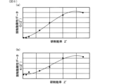
- FIG. 5A is a diagram showing a first example of a correspondence relationship between a machining state index and contact dynamic stiffness data in the first embodiment
- FIG. 5B is a diagram showing a second example of the correspondence relationship between the machining state index and contact dynamic stiffness data in the first embodiment
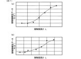
- 6A is a diagram showing a third example of a correspondence relationship between a processing state index and contact dynamic stiffness data in the first embodiment
- FIG. 6B is a diagram showing a fourth example of the correspondence relationship between the processing state index and contact dynamic stiffness data in the first embodiment.
- 6 is a flowchart showing a process of acquiring contact dynamic stiffness data for creating a contact dynamic stiffness correspondence relationship.
- 11 is a plan view of the grinding machine when acquiring contact dynamic stiffness for creating a contact dynamic stiffness correspondence relationship.
- 11 is a diagram showing the state of the grinding machine in a part of a process of obtaining contact dynamic stiffness for creating a contact dynamic stiffness correspondence relationship.
- FIG. FIG. 4 is a diagram showing an example of a correspondence relationship between a machining state index and an analytical workpiece mass in the first embodiment.
- 11 is a flowchart showing a process of acquiring the analytical workpiece mass for creating a mass correspondence relationship.
- FIG. 13 shows a machining system including a workpiece material amount determination device and a machining estimation device in a modified embodiment.
- 13 is a schematic diagram showing an interference state between a workpiece, a grinding wheel, and a rest device during grinding in a modified embodiment.
- (Embodiment 1) Configuration of machining system 1
- the workpiece material amount determination device 131, machining estimation device 3b, and machining system 1 in the present embodiment 1 will be described with reference to Fig. 1.
- the machining system 1 is intended for machining devices that perform grinding.
- the machining system 1 includes a grinding machine 2 as a machining device, and a processing unit 3.
- the grinding machine 2 rotates the workpiece W, rotates the grinding wheel T as a tool that is a rotating body, and moves the grinding wheel T relatively close to the workpiece W in a direction that intersects with the axis of the workpiece W, thereby grinding the outer or inner surface of the workpiece W.
- the grinding machine 2 can be a table traverse type grinding machine, a grinding wheel head traverse type grinding machine, or the like.
- the grinding machine 2 can also be a cylindrical grinding machine, a cam grinding machine, or the like.
- the workpiece W has a shaft portion Wa as a non-machined portion, and multiple machined portions Wb whose outer circumferential surfaces are to be ground.
- the machined portions Wb have, for example, a cylindrical outer circumferential surface that is coaxial with the shaft portion Wa.
- the workpiece W shown in FIG. 1 is only one example, and the grinding machine 2 can grind workpieces having various shapes.
- the processing unit 3 includes a control device 3a that controls the grinding machine 2, and a processing estimation device 3b that estimates the processing results.
- the control device 3a controls the grinding machine 2, thereby controlling the grinding process.
- the processing estimation device 3b inputs information used in the grinding process and performs a simulation to estimate the processing results of the workpiece W.
- the processing estimation device 3b can function as a simulation device independent of the grinding machine 2, or as a simulation device that operates in conjunction with the grinding machine 2. In the former case, for example, optimal grinding conditions can be determined without actually grinding the workpiece W. In the latter case, the processing estimation device 3b can, for example, correct the grinding conditions or operate to affect various controls by processing in parallel with the grinding of the workpiece W by the grinding machine 2.
- the processing estimation device 3b can also be an embedded system of the grinding machine 2 and the control device 3a.
- the grinding machine 2 is a table traverse type cylindrical grinding machine.
- the grinding machine 2 is configured to move the workpiece W in the axial direction of the workpiece W and move the grinding wheel T in a direction intersecting the axis of the workpiece W.
- the grinding machine 2 is configured to grind the cylindrical outer peripheral surface of the workpiece W using the grinding wheel T.
- the grinding machine 2 is equipped with a bed 10, a table 20, a spindle device 30, a tailstock device 40, a grinding wheel head 50, a sizing device 60, and a control device 3a.
- the bed 10 is installed on an installation surface.
- the bed 10 is formed so that the width (length in the Z-axis direction) of the front side in the X-axis direction (lower side in Fig. 1) is long, and the width of the back side in the X-axis direction (upper side in Fig. 1) is short.
- the bed 10 has a Z-axis guide surface 11 extending in the Z-axis direction on the upper surface on the front side in the X-axis direction. Furthermore, the bed 10 has a Z-axis drive mechanism 12 that drives along the Z-axis guide surface 11.
- the Z-axis drive mechanism 12 includes a ball screw mechanism 12a and a Z-axis motor 12b.
- the ball screw mechanism 12a extends parallel to the Z-axis guide surface 11, and the Z-axis motor 12b drives the ball screw mechanism 12a.
- a Z-axis drive circuit and a Z-axis detector 12c (not shown) are provided.
- the Z-axis drive circuit includes an amplifier circuit, and drives the Z-axis motor 12b.
- the Z-axis detector 12c is, for example, an angle detector such as an encoder, and detects the angle of the rotation shaft of the Z-axis motor 12b. Note that instead of the configuration including the ball screw mechanism 12a described above, the Z-axis drive mechanism 12 can also use a linear motor or the like.
- the bed 10 also has a guide surface 13 on the upper surface on the rear side in the X-axis direction, which extends in a direction intersecting the Z-axis direction.
- the guide surface 13 is an X-axis guide surface that extends in the X-axis direction perpendicular to the Z-axis.
- the bed 10 also has an X-axis drive mechanism 14 that drives along the X-axis guide surface 13.
- the X-axis drive mechanism 14 includes a ball screw mechanism 14a and an X-axis motor 14b.
- the ball screw mechanism 14a extends parallel to the X-axis guide surface 13, and the X-axis motor 14b drives the ball screw mechanism 14a.
- an X-axis drive circuit and an X-axis detector 14c (not shown) are provided.
- the X-axis drive circuit includes an amplifier circuit, and drives the X-axis motor 14b.
- the X-axis detector 14c is, for example, an angle detector such as an encoder, and detects the angle of the rotation shaft of the X-axis motor 14b.
- the X-axis drive mechanism 14 can also use a linear motor or the like instead of the configuration including the ball screw mechanism 14a described above.
- the table 20 is formed in an elongated shape and is supported on the Z-axis guide surface 11 of the bed 10 so as to be movable in the Z-axis direction (horizontal left and right direction).
- the table 20 is also fixed to the ball screw nut of the Z-axis ball screw mechanism 12a, and moves in the Z-axis direction by the rotational drive of the Z-axis motor 12b.
- the spindle device 30 constitutes a workpiece support device.
- the spindle device 30 supports the workpiece W and drives it to rotate.
- the spindle device 30 is disposed on one end side of the table 20 in the Z-axis direction.
- the spindle device 30 includes a spindle housing 31, a spindle 32, a spindle motor 33, a spindle center 34, a spindle detector 35, and a spindle drive circuit (not shown).
- the spindle housing 31 is fixed on the table 20.
- the spindle 32 is rotatably supported by the spindle housing 31 via a bearing.
- the spindle motor 33 drives the spindle 32 to rotate.
- the spindle center 34 supports one axial end face of the workpiece W.
- the spindle center 34 is fixed to the spindle 32 and is rotatable relative to the spindle housing 31.
- the spindle device 30 is equipped with a rotating member such as a chuck (not shown)
- the spindle center 34 may be fixed to the spindle housing 31 and installed so as to be unable to rotate relative to the spindle housing 31.
- the spindle device 30 may also be equipped with a chuck for gripping the workpiece W instead of the spindle center 34.
- the chuck is driven to rotate by being connected to the spindle 32.
- the spindle detector 35 and the spindle drive circuit are provided to drive the spindle motor 33.
- the spindle detector 35 is, for example, an angle detector such as an encoder, and detects the angle of the rotation shaft of the spindle motor 33.
- the spindle drive circuit includes an amplifier circuit, and drives the spindle motor 33.
- the tailstock device 40 together with the spindle device 30, constitutes a workpiece support device.
- the tailstock device 40 is disposed on the other end side of the table 20 in the Z-axis direction.
- the tailstock device 40 is provided so as to be movable in the Z-axis direction on the table 20.
- the tailstock device 40 includes a tailstock center 41.
- the tailstock center 41 supports the end face of the other axial end of the workpiece W.
- the tailstock center 41 may be provided so as not to rotate, or so as to be rotatable. Note that when the grinding machine 2 grinds the inner peripheral surface of the workpiece W, the tailstock device 40 is not necessary.
- the tailstock center 41 may be positioned at a fixed position relative to the workpiece W, or may be provided so as to be movable in the axial direction of the workpiece W relative to the workpiece W. In the latter case, the tailstock center 41 may be configured so that the pressing force in the axial direction of the workpiece W can be adjusted relative to the workpiece W.
- the pressing force can be controlled by a means for adjusting the spring force, a means for adjusting the fluid pressure, or the like.
- the grinding wheel head 50 is equipped with a grinding wheel T as a tool, and rotates and drives the grinding wheel T.
- the grinding wheel head 50 is equipped with a grinding wheel head body 51, a grinding wheel spindle 52, a grinding wheel motor 53, and a grinding wheel drive circuit (not shown).
- the grinding wheel T is formed in a disk shape.
- the grinding wheel T is used to grind the outer or inner surface of the workpiece W.
- the grinding wheel T is composed of multiple abrasive grains fixed with a binder.
- the abrasive grains used include general abrasive grains made of ceramic materials such as alumina and silicon carbide, and super abrasive grains such as diamond and CBN.
- Binders include vitrified (V), resinoid (B), rubber (R), silicate (S), shellac (E), metal (M), electrochemical deposition (P), and magnesia cement (Mg).
- grinding wheels T are available in configurations with and without pores. Depending on the type of binder and the presence or absence of pores, grinding wheels T may be elastically deformable or almost non-elastically deformable. In elastically deformable grinding wheels T, the elastic modulus differs depending on the type of binder, the presence or absence of pores, the porosity, etc.
- the wheel head body 51 is formed, for example, in a rectangular shape when viewed from above, and is supported on the X-axis guide surface 13 of the bed 10 so as to be movable in the X-axis direction (horizontal front-back direction).
- the wheel head body 51 is also fixed to the ball screw nut of the X-axis ball screw mechanism 14a, and moves in the X-axis direction by the rotational drive of the X-axis motor 14b.
- the wheel head body 51 constitutes a tool support device that supports the grinding wheel T.
- the grinding wheel spindle 52 is rotatably supported on the grinding wheel head body 51 via bearings.
- a grinding wheel T is fixed to the tip of the grinding wheel spindle 52, and the grinding wheel T rotates as the grinding wheel spindle 52 rotates.
- a grinding wheel motor 53 drives the grinding wheel spindle 52 to rotate.
- the bearings used may be hydrostatic bearings or rolling bearings.
- the grinding wheel motor 53 transmits the rotational driving force to the grinding wheel spindle 52, for example, via a belt. However, the grinding wheel motor 53 may be arranged coaxially with the grinding wheel spindle 52. In general, the rotation speed of the grinding wheel T driven by the grinding wheel motor 53 is faster than the rotation speed of the workpiece W driven by the spindle motor 33.
- the grinding wheel drive circuit is provided to drive the grinding wheel motor 53.
- the grinding wheel drive circuit includes an amplifier circuit, and drives the grinding wheel motor 53.
- the sizing device 60 is provided on the upper surface of the bed 10 and measures the outer diameter of the workpiece W.
- the sizing device 60 is equipped with, for example, a pair of contacts that can contact the outer peripheral surface of the workpiece W, and measures the outer diameter at the point of contact with the workpiece W.
- the control device 3a is a CNC (Computer Numerical Control) device and a PLC (Programmable Logic Controller) device that executes processing control. That is, based on the grinding program and the measurement results by the sizing device 60, the control device 3a drives the Z-axis drive mechanism 12 and the X-axis drive mechanism 14 as moving devices to control the positions of the table 20 and the grinding wheel head 50. That is, the control device 3a controls the positions of the table 20 and the grinding wheel head 50, etc., thereby moving the workpiece W and the grinding wheel T closer to and farther apart relative to each other. Furthermore, the control device 3a controls the spindle device 30 and the grinding wheel head 50. That is, the control device 3a controls the rotation of the spindle 32 and the grinding wheel T.
- CNC Computer Numerical Control
- PLC Programmable Logic Controller
- the machining estimation device 3b includes a command value acquisition unit 101, an estimation unit 102, a contact dynamic stiffness table storage unit (second correspondence relationship storage unit) 103a, a workpiece material mass table storage unit (first correspondence relationship storage unit) 103b, a workpiece support dynamic stiffness table storage unit 103c, a tool support dynamic stiffness table storage unit 103d, a machining condition acquisition unit 106, a dynamic characteristic determination unit 107, a correction amount calculation unit 108, an output unit 109, and a machining condition optimization unit 110.
- the command value acquisition unit 101 acquires command values for controlling the grinding machine 2 during grinding.
- the processing estimation device 3b is a simulation device independent of the grinding machine 2
- the command value acquisition unit 101 inputs a grinding program and configuration information of the grinding machine 2 to generate command values for controlling each part of the grinding machine 2 through calculations.
- the processing estimation device 3b functions as a simulation device that operates in conjunction with the grinding process performed by the grinding machine 2
- the command value acquisition unit 101 can acquire command values directly from the control device 3a of the grinding machine 2.
- the estimation unit 102 executes a grinding simulation using the command values acquired by the command value acquisition unit 101 to estimate at least one of the state of the workpiece W or the grinding wheel T during grinding, the shape of the workpiece W, the shape of the grinding wheel T, and the mechanical state of the grinding machine 2.
- the state of the workpiece W includes, for example, the vibration state and temperature state of the workpiece W.
- the state of the grinding wheel T includes, for example, the vibration state and temperature state of the grinding wheel T, the grinding resistance generated at each part of the outer surface of the grinding wheel T, the sharpness of the grinding wheel T, and the state of the abrasive grains that make up the grinding wheel T.
- the state of the abrasive grains includes, for example, the average protrusion amount of the abrasive grains and the abrasive grain distribution.
- the shape of the workpiece W includes the shape at an intermediate stage of the grinding process and the shape at the end of the grinding process.
- the shape of the grinding wheel T includes the shape at an intermediate stage of the grinding process and the shape at the end of the grinding process.
- the mechanical state of the grinding machine 2 includes the vibration state and temperature state of the parts that make up the grinding machine 2.
- the estimation unit 102 performs a process in which the shape of the workpiece W changes sequentially through a grinding simulation, and estimates the shape of the workpiece W, the state of the workpiece W, and the mechanical state of the grinding machine 2 as the estimation targets.
- the grinding simulation is performed assuming that the grinding wheel T does not deform.
- the estimation unit 102 can also estimate the grinding resistance generated at each part of the outer circumferential surface of the grinding wheel T.
- the estimation unit 102 includes an interference amount calculation unit 111, a grinding efficiency calculation unit 112, a grinding characteristic determination unit 113, and a grinding resistance calculation unit 114.
- the interference amount calculation unit 111 calculates the amount of interference between the workpiece W and the grinding wheel T based on the relative positions of the workpiece W and the grinding wheel T, the outer peripheral surface shape of the workpiece W, and the outer peripheral surface shape of the grinding wheel T obtained using the command values acquired by the command value acquisition unit 101.
- the amount of interference corresponds to the amount of radial grinding of the workpiece W at each circumferential portion of the workpiece W.
- the amount of interference is the amount of removal of the workpiece W ground by the grinding wheel T, more specifically, the amount of radial removal of the workpiece W at each circumferential portion of the workpiece W.
- the amount of interference is the volume of the portion where the workpiece W interferes with the grinding wheel T (the shaded portion in FIG. 3: the interference area).
- the interference amount calculation unit 111 calculates the amount of interference geometrically by arithmetic processing.
- the interference amount calculation unit 111 stores the outer peripheral surface shape of the workpiece W and the outer peripheral surface shape of the grinding wheel T.
- the outer peripheral surface shape of the workpiece W is expressed by a group of multiple radial line segments on a polar coordinate system with the rotation center Ow of the workpiece W as the origin.
- the interference amount calculation unit 111 stores a group of multiple line segments connecting the division points (white points in FIG. 4) on the outer peripheral surface obtained by dividing the workpiece W equiangularly ( ⁇ ) and the rotation center Ow (origin) of the workpiece W as the outer peripheral surface shape of the workpiece W.
- the division points shown by white points in FIG. 4 are stored as the outer peripheral surface shape of the workpiece W before it is removed by the grinding wheel T.
- the interference amount calculation unit 111 determines the intersections (black dots in FIG. 4) between each line segment of the workpiece W and the line representing the outer peripheral shape of the grinding wheel T from the relative position (center distance) between the workpiece W and the grinding wheel T and the outer peripheral shape of the grinding wheel T.
- the interference amount calculation unit 111 stores the determined intersections (black dots in FIG. 4) as the outer peripheral shape of the workpiece W after it has been removed by the grinding wheel T. In other words, the interference amount calculation unit 111 changes the stored outer peripheral shape of the workpiece W.
- the interference amount calculation unit 111 subtracts the area of the triangle ⁇ Ow-b1-b2 consisting of the points b1 and b2 (intersection with the grinding wheel T) after removal and the origin Ow from the area of the triangle ⁇ Ow-a1-a2 consisting of the origin Ow and adjacent points a1 and a2 among the points that define the outer peripheral surface shape of the workpiece W before removal.
- the areas after subtraction are calculated for all adjacent points that define the outer peripheral surface shape of the workpiece W.
- the interference amount calculation unit 111 adds up the areas after each subtraction and multiplies the total area thus added up by the thickness of the workpiece W to calculate the amount of interference (amount of removal).
- the area of the portion to be removed is calculated by calculating the areas of the two types of triangles and then calculating the difference between these areas.
- the area of the portion to be removed may be calculated by directly calculating the quadrangle a1-a2-b1-b2.
- the grinding efficiency calculation unit 112 calculates the grinding efficiency (processing efficiency) Z' based on the amount of interference calculated by the interference amount calculation unit 111.
- the grinding efficiency Z' calculates the amount of interference per unit time, i.e., the volume of the workpiece W ground by the grinding wheel T in unit time.
- the grinding characteristic determination unit 113 determines the grinding characteristic kc based on the material of the workpiece W, the type of abrasive grains and binder of the grinding wheel T, and the condition of the outer peripheral surface of the grinding wheel T.
- the condition of the outer peripheral surface of the grinding wheel T is expressed, for example, using an index that indicates the wear state and sharpness of the abrasive grains of the grinding wheel T.
- the grinding characteristic determination unit 113 stores the grinding characteristics in each state in advance through experiments, analysis, etc.
- the grinding resistance calculation unit 114 calculates the grinding resistance Fn in the normal direction (X-axis direction) of the outer peripheral surface of the workpiece W based on the grinding efficiency Z' and the grinding characteristic kc.
- the grinding characteristic kc has a nearly linear relationship such that the grinding resistance Fn in the normal direction (X-axis direction) increases as the grinding efficiency Z' increases.
- the grinding characteristic kc changes this relationship, for example, when the grinding wheel T is worn. For example, when the grinding wheel T is worn, the grinding resistance Fn in the normal direction changes to increase with respect to the grinding efficiency Z'.
- the contact dynamic stiffness table memory unit 103a stores contact dynamic stiffness data (Ci(Z'), Ki(Z')) between the workpiece W and the grinding wheel T.
- the contact dynamic stiffness table memory unit 103a constitutes a second correspondence relationship memory unit 103a that stores the correspondence between the machining state index described below and the contact dynamic stiffness data (Ci(Z'), Ki(Z')).
- the workpiece support dynamic stiffness table memory unit 103c stores workpiece support dynamic stiffness data (Cw, Kw) in the spindle unit 30 and tailstock unit 40 as workpiece support devices.
- the workpiece support dynamic stiffness table memory unit 103c stores the correspondence between the machining conditions and the workpiece support dynamic stiffness data (Cw, Kw).
- the tool support dynamic stiffness table memory unit 103d stores tool support dynamic stiffness data (Ct, Kt) in the wheel head body 51 as a grinding wheel support device.
- the tool support dynamic stiffness table storage unit 103d stores the correspondence between the machining conditions and the tool support dynamic stiffness data (Ct, Kt).
- the machining condition acquisition unit 106 acquires the machining conditions when performing grinding by the grinding machine 2.
- the machining condition acquisition unit 106 acquires the machining conditions at the time of estimation by the estimation unit 102 (at the time of processing).
- the machining conditions acquired by the machining condition acquisition unit 106 are information used by the dynamic characteristic determination unit 107 to calculate each dynamic stiffness.
- the acquired machining conditions are, for example, the type of workpiece W, the type of workpiece support member, the type of grinding wheel T, and the pressing forces by the spindle center 34 and the tailstock center 41.
- the processing condition acquisition unit 106 acquires the conditions for determining the dynamic stiffness by inputting the mechanical configuration and grinding program of the grinding machine 2. Also, if the processing estimation device 3b functions as a simulation device that operates in conjunction with the grinding process by the grinding machine 2, the processing condition acquisition unit 106 may acquire the conditions for determining the dynamic stiffness by inputting the mechanical configuration and grinding program of the grinding machine 2 from the control device 3a, or may acquire information regarding the conditions directly from the control device 3a of the grinding machine 2.
- the dynamic characteristic determining unit 107 determines dynamic stiffness data and analytical workpiece mass (M'w(Z')) that affect grinding.
- the dynamic characteristic determining unit 107 separately determines the contact dynamic stiffness data (Ci(Z'), Ki(Z')), workpiece support dynamic stiffness data (Cw, Kw), tool support dynamic stiffness data (Ct, Kt), and analytical workpiece mass (M'w(Z')) shown in FIG. 5. That is, the dynamic characteristic determining unit 107 includes a contact dynamic stiffness determining unit 121, a workpiece mass determining unit 122, a workpiece support dynamic stiffness determining unit 123, and a tool support dynamic stiffness determining unit 124.
- the contact dynamic stiffness (Ci(Z'), Ki(Z')), workpiece support dynamic stiffness (Cw, Kw), tool support dynamic stiffness (Ct, Kt) and workpiece mass (Mw) will be explained with reference to FIG. 5.
- the contact dynamic stiffness (Ci(Z'), Ki(Z')) is the dynamic stiffness between the workpiece W and the grinding wheel T.
- the workpiece support dynamic stiffness (Cw, Kw) includes the workpiece W and is the dynamic stiffness of the workpiece W side relative to the table 20, spindle unit 30 and unit 40.
- the tool support dynamic stiffness (Ct, Kt) includes the grinding wheel T and is the dynamic stiffness relative to the wheel head 50.
- the workpiece mass (Mw) is the mass of the workpiece W.
- Contact dynamic stiffness is the dynamic stiffness between the workpiece W and the grinding wheel T, and is the dynamic stiffness exhibited by the contact between the workpiece W and the grinding wheel T during grinding.
- Contact dynamic stiffness is defined by a damping coefficient Ci and a spring constant Ki.
- contact static stiffness which is distinguished from contact dynamic stiffness, is represented only by the spring constant K and does not include the damping coefficient C.
- the damping coefficient Ci in contact dynamic stiffness is a value that represents the relationship between the relative speed between the workpiece W and the grinding wheel T and the external force that the workpiece W or the grinding wheel T receives.
- the spring constant Ki is a value that represents the relationship between the relative position between the workpiece W and the grinding wheel T and the external force that the workpiece W or the grinding wheel T receives.
- the contact dynamic stiffness corresponds to a processing condition index that changes according to the state of processing of the workpiece W by the tool (grinding wheel T) in the processing device 2 during grinding.
- the processing condition index include processing efficiency (grinding efficiency Z'), contact arc length L, and g/a (grain cutting depth/grain cutting edge interval).
- the contact dynamic stiffness correspondence relationship which is the correspondence relationship between the processing condition index and the contact dynamic stiffness data (Ci(Z'), Ki(Z')), can be obtained by performing actual measurement.
- the contact arc length L is the arc length of the outer circumferential surface of the grinding wheel T that is in contact with the workpiece W during grinding, in a cross section perpendicular to the axis of the grinding wheel T, as shown in FIG. 3.
- the contact arc length L changes depending on the feed speed of the grinding wheel T in the X-axis direction, the outer diameter of the grinding wheel T, the outer diameter of the workpiece W, etc.
- FIGs. 6(a) and (b) and 7(a) and (b) show examples of the contact dynamic stiffness correspondence relationship between the machining state index and the contact dynamic stiffness data (Ci(Z'), Ki(Z')).
- the grinding efficiency Z' is used as the machining state index
- the damping coefficient Ci and the spring constant Ki in the contact dynamic stiffness have a nonlinear relationship with respect to the grinding efficiency Z', not a linear relationship (proportional relationship).
- the contact dynamic stiffness correspondence relationship between the machining state index and the contact dynamic stiffness data (Ci(Z'), Ki(Z')) is a relationship in which the degree of change of the contact dynamic stiffness data (Ci(Z'), Ki(Z')) with respect to the machining state index varies.
- a function representing a curve whose slope changes continuously can be specified as an approximate formula.
- the approximation formula can be a higher-order function; for example, the curves shown in Figures 6(a) and (b) are curves defined by cubic functions.
- the contact arc length L is used as the machining state index.
- the machining state index shows a tendency similar to that when the grinding efficiency Z' is used, but it tends to be difficult to fit the curve represented by a cubic function compared to when the machining state index is the grinding efficiency Z'.
- the machining state index is the grinding efficiency as shown in Figures 6(a) and (b)
- the correspondence relationship between the machining state index and the contact dynamic stiffness data shows a tendency similar to that in the case of the grinding efficiency Z' shown in Figures 6(a) and (b).
- the contact dynamic stiffness correspondence relationship may be a combination of multiple straight lines on the quadratic plane instead of the curve.
- the contact dynamic stiffness correspondence relationship may be in the form of a data table consisting of multiple data correspondence relationships instead of being specified as a function such as an approximation equation.
- the machining state index is acquired by the machining state index acquisition unit 125 provided in the contact dynamic stiffness determination unit 121, and the contact dynamic stiffness correspondence, which is the correspondence between the machining state index and the contact dynamic stiffness data (Ci(Z'), Ki(Z')), is stored in the second correspondence storage unit 103a.
- the contact dynamic stiffness data (Ci(Z'), Ki(Z')) is determined by the contact dynamic stiffness determination unit 121 based on the machining state index acquired by the machining state index acquisition unit 125.
- the machining state index acquisition unit 125, the second correspondence storage unit 103a, and the contact dynamic stiffness determination unit 121 constitute the contact dynamic stiffness determination device 130.
- the measuring jig 4 is attached to the grinding machine 2 and the workpiece W (S1).
- the measuring jig 4 is a non-contact vibrator, and is a device that applies a vibration force to the workpiece W.
- the measuring jig 4 is provided on the upper surface of the table 20. The fixed position of the measuring jig 4 in the Z-axis direction on the upper surface of the table 20 is adjustable.
- the measuring jig 4 holds the workpiece W with the workpiece W inserted therethrough.
- a part of the shaft portion Wa which is the non-machined portion of the workpiece W, is inserted into the measuring jig 4, and multiple machined portions Wb to be ground are located outside the measuring jig 4.
- the workpiece W inserted and held in the measuring jig 4 is supported by the spindle device 30 and tailstock device 40, in the same way as during normal grinding.
- the measuring jig 4 includes a housing 131, an electromagnet 132, a rotor 133, a lock nut 134, a displacement sensor 135, and a control device 136.
- the housing 131 is fixed to the upper surface of the table 20 of the grinding machine 2. Furthermore, the housing 131 is formed with a hole 131a that penetrates in the Z-axis direction.
- the electromagnet 132 is embedded in the housing 131.
- the rotor 133 is attached to the outer circumferential surface of the workpiece W and is provided integrally with the workpiece W.
- the rotor 133 is made of a magnetic material and moves due to the magnetic force generated by the electromagnet 132.
- the rotor 133 is formed in a cylindrical shape, and the outer circumferential surface of the rotor 133 is disposed with a predetermined gap from the inner circumferential surface of the housing 131. This gap is the distance that the rotor 133 can move relative to the housing 131.
- the inner circumferential surface of the rotor 133 is formed according to the shape of the outer circumferential surface of the workpiece W.
- the lock nut 134 is a member for fixing the rotor 133 to the workpiece W. The method of fixing the rotor 133 is not limited to the means using the lock nut 134, and various means can be adopted.
- the displacement sensor 135 is provided at a position close to the inner circumferential surface of the housing 131, and measures the distance to the outer circumferential surface of the rotor 133. In other words, when the rotor 133 is vibrated by the electromagnet 132, the displacement sensor 135 measures the displacement of the rotor 133 in the direction in which the rotor 133 approaches or moves away from the inner circumferential surface of the housing 131 (hereinafter referred to as radial displacement).
- the control device 136 supplies a drive current to the electromagnet 132 so that the electromagnet 132 applies a vibration force.
- the control device 136 also acquires the displacement measured by the displacement sensor 135, i.e., the radial displacement of the rotor 133.
- the housing 131 of the measuring jig 4 is attached to the table 20. Furthermore, the workpiece W to which the rotor 133 is attached is supported by the spindle device 30 and the tailstock device 40. At this time, the position of the housing 131 is adjusted so that the outer circumferential surface of the rotor 133 faces the inner circumferential surface of the housing 131 of the measuring jig 4, as shown in FIG. 10(b).
- grinding is started (S2). That is, while the workpiece W and the grinding wheel T are rotating, the grinding wheel T is moved in the X-axis direction to grind the outer peripheral surface of the processed portion Wb of the workpiece W.
- an excitation force is applied by the measuring jig 4 (S3).
- the excitation force is applied by the measuring jig 4 while the workpiece W is being ground by the grinding wheel T.
- the excitation force applied may be impulse excitation or sweep excitation in which the excitation frequency is changed continuously.
- the excitation force is applied by the control device 136 of the measuring jig 4 supplying a current to the electromagnet 132.
- the excitation force is controlled by the current supplied to the electromagnet 132 by the control device 136.
- the displacement sensor 135 of the measuring jig 4 measures the radial displacement that occurs in the workpiece W when an excitation force is applied to the workpiece W.
- the overall dynamic stiffness data (Ccom, Kcom) during grinding is calculated (S6).
- the overall dynamic stiffness data (Ccom, Kcom) is the overall (composite) dynamic stiffness data represented by the above-mentioned contact dynamic stiffness data (Ci(Z'), Ki(Z')), workpiece support dynamic stiffness data (Cw, Kw), and tool support dynamic stiffness data (Ct, Kt).
- the overall dynamic stiffness data (Ccom, Kcom) is represented as the sum of the above-mentioned contact dynamic stiffness data (Ci(Z'), Ki(Z')), workpiece support dynamic stiffness data (Cw, Kw), and tool support dynamic stiffness data (Ct, Kt).
- the radial displacement measured by the displacement sensor 135 of the measuring jig 4 is measured when an excitation force is applied to the workpiece W during grinding. Therefore, the measured displacement is affected by the contact dynamic stiffness data (Ci(Z'), Ki(Z')), workpiece support dynamic stiffness data (Cw, Kw), and tool support dynamic stiffness data (Ct, Kt).
- the calculation of the overall dynamic stiffness data (Ccom, Kcom) is data generated from the relationship between the excitation force and the radial displacement of the workpiece W when an excitation force is applied to the workpiece W during grinding.
- the workpiece support dynamic stiffness data (Cw, Kw) and the tool support dynamic stiffness data (Ct, Kt) are acquired (S7).
- the workpiece support dynamic stiffness data (Cw, Kw) and the tool support dynamic stiffness data (Ct, Kt) are acquired in advance by a hammering test or the like.
- the contact dynamic stiffness data (Ci(Z'), Ki(Z')) is calculated (S8).
- the contact dynamic stiffness data (Ci(Z'), Ki(Z')) is obtained by subtracting the workpiece support dynamic stiffness data (Cw, Kw) and the tool support dynamic stiffness data (Ct, Kt) from the overall dynamic stiffness data (Ccom, Kcom).
- the interpolation process is a process in which the contact dynamic stiffness data (Ci, Ki) obtained by actual measurement is used to obtain contact dynamic stiffness data (Ci(Z'), Ki(Z')) under grinding conditions different from the actual measurement.
- an empirical formula that defines the relationship between the contact arc length L, the damping coefficient Ci, and the spring constant Ki can be used.
- the interpolation process can also apply an empirical formula, machine learning, theoretical calculation, etc. In this way, the contact dynamic stiffness correspondence relationship with the processing condition index (grinding efficiency) shown in Figures 6(a) and (b) can be created using the contact dynamic stiffness data (Ci(Z'), Ki(Z')).
- the workpiece support dynamic stiffness is the dynamic stiffness related to support in the spindle unit 30 and tailstock unit 40 shown in FIG. 1, and is the dynamic stiffness exhibited when the workpiece W is supported by the spindle unit 30 and tailstock unit 40 as the workpiece support devices constituting the grinding machine 2.
- the workpiece support dynamic stiffness is defined by a damping coefficient Cw and a spring constant Kw.
- the damping coefficient Cw is a value that represents the relationship between the relative speed of the workpiece W with respect to the reference positions of the spindle unit 30 and tailstock unit 40, and the external force that the workpiece W receives.
- the spring constant Kw is a value that represents the relationship between the relative position of the workpiece W with respect to the reference positions of the spindle unit 30 and tailstock unit 40, and the external force that the workpiece W receives.
- the workpiece support dynamic stiffness data (Cw, Kw) is stored in the workpiece support dynamic stiffness table storage unit 103c so as to correspond to the above-mentioned machining conditions.
- the workpiece support dynamic stiffness data (Cw, Kw) is data that changes as the contact state between the tailstock center 41 and the workpiece W changes due to a change in the pressing force by the tailstock center 41.
- the workpiece support dynamic stiffness data (Cw, Kw) can be obtained, for example, by performing a hammering test while changing the pressing force by the tailstock center 41 in a state in which the workpiece W is supported by the spindle center 34 and the tailstock center 41.
- the workpiece support dynamic stiffness determination unit 123 determines the workpiece support dynamic stiffness data (Cw, Kw) corresponding to the machining conditions acquired by the machining condition acquisition unit 106 from the workpiece support dynamic stiffness table stored in the workpiece support dynamic stiffness table storage unit 103c.
- the analytical workpiece weight (M'w(Z')) is the analytical mass of the workpiece W, and is a value correlated with the machining state index.
- a mass correspondence relationship, which is a correspondence relationship between the analytical workpiece weight (M'w(Z')) and the machining state index, is stored in the workpiece weight table storage unit 103b, which serves as a first correspondence relationship storage unit.
- the machining state index in the mass correspondence relationship can be the same as in the case of the contact dynamic stiffness correspondence relationship described above.
- the mass correspondence relationship between the machining state index and the analytical workpiece mass (M'w(Z')) shows an example of the mass correspondence relationship between the machining state index and the analytical workpiece mass (M'w(Z')).
- the analytical workpiece mass (M'w(Z')) has a nonlinear relationship, not a linear relationship (proportional relationship), with respect to the grinding efficiency Z' as the machining state index.
- the mass correspondence relationship between the machining state index and the analytical workpiece mass (M'w(Z')) is a relationship in which the degree of change of the analytical workpiece mass (M'w(Z')) with respect to the machining state index varies.
- a function representing a curve whose slope changes continuously can be specified as an approximation formula.
- the approximation formula can be a higher-order function, and for example, the curve shown in FIG. 11 is a curve specified by a cubic function.
- the mass correspondence relationship may be a curve in which a plurality of straight lines are connected in the quadratic plane instead of the curve.
- the mass correspondence may be in the form of a data table consisting of correspondences between multiple pieces of data.
- Figure 11 shows the case where the machining condition index is the grinding efficiency Z', but even when the machining condition index is the contact arc length L or g/a, the mass correspondence relationship between the machining condition index and the analytical workpiece mass (M'w(Z')) shows roughly the same tendency as in the case of grinding efficiency Z' shown in Figure 11, but it is preferable to use grinding efficiency Z' as the machining condition index, just as in the case of the contact dynamic stiffness correspondence relationship.
- the machining state index is acquired by the machining state index acquisition unit 125, and the mass correspondence, which is the correspondence between the machining state index and the analytical workpiece amount (M'w(Z')), is stored in the first correspondence storage unit 103b.
- the analytical workpiece amount (M'w(Z')) is then determined by the workpiece amount determination unit 122 based on the machining state index acquired by the machining state index acquisition unit 125.
- the machining state index acquisition unit 125, the first correspondence storage unit 103b, and the workpiece amount determination unit 122 constitute the workpiece amount determination device 131.
- Analytical workpiece mass acquisition process for creating mass correspondence relationship The analytical workpiece mass (M'w(Z')) in the mass correspondence relationship is created based on the workpiece dynamic characteristics (Mw, Cw, Kw) during non-machining and the contact dynamic stiffness data (Ci(Z'), Ki(Z')).
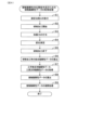
- the workpiece mass acquisition process for creating the mass correspondence relationship will be described below with reference to the flow chart shown in FIG. 12.
- step S11 shown in FIG. 12 the vibration device 4 is used to measure the dynamic characteristics during machining at the detection position We of the displacement sensor 135 in each of the multiple states in which the grinding efficiency Z' is changed according to the process shown in FIG. 8. At this time, since the grinding efficiency Z' is changed, the grinding resistance changes in correlation with the grinding efficiency Z', and therefore the grinding resistance can be expressed as Fn(Z').
- step S12 the dynamic characteristics (Mw, Cw, Kw) during non-machining at the detection position We of the displacement sensor 135 are analyzed.
- the dynamic characteristics are set as initial dynamic characteristics (initial masses Mw, Cw, Kw) using, for example, actual measured values from a hammering test during non-machining.
- step S13 the contact dynamic stiffness data (Ci(Z'), Ki(Z')) is identified so that the dynamic characteristics (initial masses Mw, Cw, Kw) during non-machining at the detection position We of the displacement sensor 135 match the dynamic characteristics during machining of each of the multiple grinding efficiencies Z' at the detection position We of the displacement sensor 135.
- step S13 the initial masses Mw, Cw, Kw are fixed parameters, and Ci(Z') and Ki(Z') are variable parameters, and the contact dynamic stiffness data (Ci(Z'), Ki(Z')) is added to the dynamic characteristics during non-machining (initial masses Mw, Cw, Kw), and the dynamic characteristics of the analytical model (initial masses Mw, Cw, Kw, Ci(Z'), Ki(Z')) are identified so that the dynamic characteristics during machining of each of the multiple grinding efficiencies Z' match the dynamic characteristics during machining of each of the multiple grinding efficiencies Z'.
- the excitation force frequency-compliance characteristics using the dynamic characteristics of the analytical model did not completely match the excitation force frequency-compliance characteristics during machining for each of the multiple grinding efficiencies Z', which were actually measured values. Therefore, among the dynamic characteristics of the analytical model, the workpiece mass Mw was set as the modified workpiece mass M'w(Z'), which is a variable parameter, and an identification process was performed for the analytical modified workpiece mass (M'w(Z')) at the machining point position Wb so that the dynamic characteristics of the analytical model matched the dynamic characteristics during machining for each of the multiple grinding efficiencies Z'.
- step S14 the dynamic characteristics of the analytical model are defined as (M'w(Z'), Cw, Kw, Ci(Z'), Ki(Z')), with Cw, Kw, Ci(Z') and Ki(Z') being fixed parameters and M'w(Z') being a variable parameter. Then, the analytical corrected workpiece mass (M'w(Z')) at the machining point position is determined so that the dynamic characteristics of the analytical model match the dynamic characteristics during machining of each of the multiple grinding efficiencies Z'.
- the analytical corrected workpiece mass (M'w(Z')) is expressed by the following equation (1) based on the equation of motion.
- the analytical workpiece mass (M'w(Z')) correlates with the machining efficiency (grinding efficiency) Z'
- the contact dynamic stiffness data (Ci(Z'), Ki(Z')) also correlates with the machining efficiency (grinding efficiency) Z'.
- the detection position We of the displacement sensor 135 and the processing point position Wb are different positions, but the two positions may be the same.
- the tool support dynamic stiffness is the dynamic stiffness related to support in the wheel head body 51 shown in Fig. 1, and is the dynamic stiffness exhibited when the grinding wheel T is supported by the wheel head body 51 as a grinding wheel support device constituting the grinding machine 2.
- the tool support dynamic stiffness is defined by a damping coefficient Ct and a spring constant Kt.
- the damping coefficient Ct is a value that represents the relationship between the relative speed of the grinding wheel T with respect to a reference position in the wheel head body 51 and the external force that the grinding wheel T receives.
- the spring constant Kt is a value that represents the relationship between the relative position of the grinding wheel T with respect to a reference position in the wheel head body 51 and the external force that the grinding wheel T receives.
- the tool support dynamic stiffness data (Ct, Kt) is stored in the tool support dynamic stiffness table storage unit 103d so as to correspond to the above-mentioned machining conditions.
- the tool support dynamic stiffness table storage unit 103d stores the tool support dynamic stiffness data (Ct, Kt) for each type of grinding wheel T, for example.
- the tool support dynamic stiffness table storage unit 103d may store the correspondence between the machining conditions and the tool support dynamic stiffness data (Ct, Kt).
- the tool support dynamic stiffness determination unit 124 determines the tool support dynamic stiffness data (Cw, Kw) corresponding to the machining conditions acquired by the machining condition acquisition unit 106 from the tool support dynamic stiffness table stored in the tool support dynamic stiffness table storage unit 103d.
- the tool mass Ms of the tool T is expressed by the following formula (2) based on the equation of motion.
- correction amount calculation unit 108 calculates the correction amount for the relative displacement of the grinding wheel T and workpiece W in the X-axis direction due to the grinding resistance, based on each dynamic stiffness data and the analytical workpiece material mass (M'w(Z')) determined by the dynamic characteristic determination unit 107. The correction amount for the displacement can be found from each dynamic stiffness data, the analytical workpiece material mass (M'w(Z')), and the grinding resistance.
- the correction amount for the displacement can be calculated from the grinding resistance, the contact dynamic stiffness data (Ci(Z'), Ki(Z')), the workpiece support dynamic stiffness data (Cw, Kw), the tool support dynamic stiffness data (Ct, Kt), and the analytical workpiece material mass (M'w(Z')).
- the correction amount calculation unit 108 outputs the calculated correction amount to the estimation unit 102.
- the estimation unit 102 estimates the estimation target based on the relative position between the workpiece W and the grinding wheel T acquired by the command value acquisition unit 101, the outer peripheral surface shape of the workpiece W, and the outer peripheral surface shape of the grinding wheel T.
- the relative position between the workpiece W and the grinding wheel T is different from the relative position based on the command value.
- the estimation unit 102 uses the relative position between the workpiece W and the grinding wheel T, which is obtained by adding the correction amount calculated by the correction amount calculation unit 108 to the relative position acquired by the command value acquisition unit 101. In other words, the estimation unit 102 estimates the estimation target based on the relative position based on the command value and the correction amount calculated using each dynamic stiffness data.
- the correction amount calculation unit 108 outputs the calculated correction amount to the interference amount calculation unit 111 of the estimation unit 102.
- the interference amount calculation unit 111 calculates the amount of interference between the workpiece W and the grinding wheel T based on the relative position between the workpiece W and the grinding wheel T, the outer peripheral surface shape of the workpiece W, and the outer peripheral surface shape of the grinding wheel T acquired by the command value acquisition unit 101. However, due to grinding resistance, the relative position between the workpiece W and the grinding wheel T is different from the relative position determined by the command value.
- the interference amount calculation unit 111 uses the relative position obtained by adding the correction amount calculated by the correction amount calculation unit 108 to the relative position acquired by the command value acquisition unit 101 as the relative position between the workpiece W and the grinding wheel T used to calculate the amount of interference. In other words, the interference amount calculation unit 111 calculates the amount of interference based on the relative position according to the command value and the correction amount calculated using each dynamic stiffness data.
- the interference amount calculation unit 111 calculates the amount of interference taking into account the amount of correction, so the grinding efficiency calculation unit 112, the grinding characteristic determination unit 113, and the grinding resistance calculation unit 114 obtain the grinding efficiency Z', the grinding characteristic kc, and the grinding resistance Fn obtained based on the amount of interference taking into account the amount of correction.
- the output unit 109 outputs the estimation target estimated by the estimation unit 102.
- the output unit 109 estimates at least one of the state of the workpiece W or the grinding wheel T during grinding, the shape of the workpiece W, the shape of the grinding wheel T, and the mechanical state of the processing system 1 (corresponding to the mechanical state of the grinding machine 2).
- the output unit 109 may, for example, teach the estimation result to a teaching device (not shown).
- the machining condition optimization unit 110 optimizes the machining conditions based on the estimation results by the estimation unit 102.
- the machining condition optimization unit 110 can then output the optimized machining conditions to the control device 3a of the grinding machine 2.
- the control device 3a can perform grinding using the optimized machining conditions.
- the control device 3a can also control machining using various dynamic stiffness data and the analytical workpiece mass (M'w(Z')) determined by the dynamic characteristic determination unit 107, regardless of the estimation results.
- the analytical workpiece weight (M'w(Z')) is determined based on the mass correspondence relationship between the stored machining state index and the analytical workpiece weight (M'w(Z')) and the acquired machining state index. This makes it possible to determine the analytical workpiece weight (M'w(Z')) with high accuracy based on the correspondence relationship with the machining state index.
- the analytical workpiece quantity (M'w(Z')) in the above mass correspondence relationship is created based on the workpiece dynamic characteristics (Mw, Cw, Kw) during non-machining and the contact dynamic stiffness data (Ci(Z'), Ki(Z')). This makes it possible to obtain changes in the analytical workpiece quantity (M'w(Z')) more accurately, and therefore makes it possible to determine the analytical workpiece quantity (M'w(Z')) with high accuracy.
- the contact dynamic stiffness data (Ci(Z'), Ki(Z')) is data generated based on the relationship between the excitation force and the displacement of the workpiece W when an excitation force is applied to the workpiece W while the workpiece W is being machined by the tool T.
- the contact dynamic stiffness data (Ci(Z'), Ki(Z')) accurately represents the dynamic stiffness between the workpiece W and the grinding wheel T, so that the analytical workpiece material quantity (M'w(Z')) can be determined with high accuracy.
- the mass correspondence relationship is defined as an approximation of a function that represents a curve whose slope changes continuously in a quadratic plane with the horizontal axis representing the machining state index and the vertical axis representing the analytical workpiece quantity.
- the mass correspondence relationship is defined as an approximation of a function that represents a curve that is a nonlinear relationship, the change in the analytical workpiece quantity can be obtained more accurately, and the analytical workpiece quantity (M'w(Z')) can be determined with high precision.
- the machining state index is the machining efficiency of the workpiece W by the tool T. Since the machining efficiency is closely related to the machining state of the workpiece W, by using the machining efficiency as the machining state index, the analytical workpiece material amount (M'w(Z')) can be determined with high accuracy according to the machining state of the workpiece W.
- the processing device 2 is a cylindrical grinding machine that grinds the cylindrical outer peripheral surface of the workpiece W with a grinding wheel T, which is a tool, and is equipped with a workpiece support device consisting of a spindle device 30 that supports one axial end of the workpiece W and rotates it, and a tailstock center 41 that supports the other axial end of the workpiece W.
- the processing condition index is the grinding efficiency Z' of the workpiece W by the grinding wheel T.
- the analytical workpiece weight (M'w(Z')) is more likely to fit the curve represented by a cubic function, making it easier to create an approximation equation and allowing the analytical workpiece weight (M'w(Z')) to be determined with higher accuracy.
- the processing device 2 is a cylindrical grinding machine that grinds the cylindrical outer peripheral surface of the workpiece W using a grinding wheel T as a tool, and is equipped with a workpiece support device composed of a spindle device 30 that supports one axial end of the workpiece W and rotates it, and a tailstock center 41 that supports the other axial end of the workpiece W.
- the processing condition index is the contact arc length L of the grinding wheel T with the workpiece W. This makes it possible to easily obtain the processing condition index and reduce the calculation load.
- the machining estimation device 3b of the present embodiment 1 also includes a workpiece material quantity determination device 131 and estimates the machining result of the workpiece W in the machining device 2.
- the machining estimation device 3b also includes a second correspondence relationship storage unit 103a that stores a contact dynamic stiffness correspondence relationship, which is a correspondence relationship between the machining state index (Z') and the contact dynamic stiffness data (Ci(Z'), Ki(Z')), a contact dynamic stiffness determination unit 121 that determines the contact dynamic stiffness data (Ci(Z'), Ki(Z')) based on the machining state index (Z') and the contact dynamic stiffness correspondence relationship acquired by the machining state index acquisition unit 125, and an estimation unit 102 that estimates the machining result of the workpiece W using the contact dynamic stiffness data (Ci(Z'), Ki(Z')) determined by the contact dynamic stiffness determination unit and the analytical workpiece material quantity (M'w(Z')) determined by the workpiece material quantity determination unit 122.
- the contact dynamic stiffness data in the contact dynamic stiffness correspondence relationship is data generated based on the relationship between the excitation force and the displacement of the workpiece W when an excitation force is applied to the workpiece W while the workpiece W is machined by the tool T.
- the contact dynamic stiffness data (Ci(Z'), Ki(Z')) accurately represents the dynamic stiffness between the workpiece W and the grinding wheel T, making it possible to estimate the machining result with higher accuracy.
- the machining estimation device 3b of this embodiment 1 is equipped with a workpiece support dynamic stiffness determination unit 123 that determines workpiece support dynamic stiffness data in the workpiece support devices 30, 40 that constitute the machining device 2 when the workpiece W is supported by the workpiece support devices 30, 40, a tool support dynamic stiffness determination unit 124 that determines tool support dynamic stiffness data in the tool support device 51 that constitutes the machining device 2 when the tool T is supported by the tool support device 51, and a correction amount calculation unit 108 that calculates a correction amount for the relative position between the tool T and the workpiece W based on the contact dynamic stiffness data (Ci(Z'), Ki(Z')), tool support dynamic stiffness data (Ct, Kt), workpiece support dynamic stiffness data (Cw, Kw) and the analytical workpiece material mass (M'w(Z')), and the estimation unit 102 estimates the machining result of the workpiece W by the tool T based on the command value and the correction amount for machining the workpiece W.
- the machining estimation device 3b uses the analytical workpiece material mass (M'w(Z')) calculated with high precision, so that the machining result of the workpiece W can be estimated with high precision.
- the machining estimation device 3b further includes a machining condition optimization unit 110 that optimizes the machining conditions of the workpiece W based on the machining results estimated by the estimation unit 102, and the machining device 2 is configured to machine the workpiece W with the tool T based on the optimized machining conditions.
- the workpiece W can be machined under machining conditions optimized based on the machining results estimated with high accuracy, so that the workpiece W can be stably produced with high accuracy and manufacturing costs can be reduced.
- the processing device 2 is provided with a rest device 70.
- the rest device 70 is provided with a first arm 71 and a second arm 72, and is configured to support the lower part W1 of the workpiece W and the part W2 opposite the tool T by both arms 71, 72 in a sliding manner.
- the rest device 70 prevents the workpiece W from being deformed so as to separate from the tool T during processing.
- the dynamic characteristics determination unit 107 can determine the dynamic characteristics taking this into account. In this case, the same effect as in the first embodiment can be achieved. Note that when the rest device 70 is provided, the workpiece W may be supported by either one arm or both arms.
Landscapes
- Engineering & Computer Science (AREA)
- Mechanical Engineering (AREA)
- Constituent Portions Of Griding Lathes, Driving, Sensing And Control (AREA)
Abstract
工作物質量決定装置(131)は、工具(T)により工作物(W)を加工する加工装置(2)において、加工中の動特性を解析するための解析上の工作物質量(M'w(Z'))を算出する工作物質量決定装置であって、工具(T)による工作物(W)の加工の状態に応じて変化する加工状態指数(Z')と上記解析上の工作物質量(M'w(Z'))との対応関係である質量対応関係を記憶する第1対応関係記憶部(103b)と、上記加工状態指数(Z')を取得する加工状態指数取得部(125)と、取得された上記加工状態指数(Z')と上記質量対応関係とに基づいて、上記解析上の工作物質量(M'w(Z'))を決定する工作物質量決定部(122)と、を備える。
Description
本開示は、工作物質量決定装置、加工推定装置及び加工システムに関する。
工作物を砥石車により研削加工する研削加工装置において、加工結果を高精度に推定するには、推定過程において工作物と砥石車との相対位置の補正を行う必要がある。特許文献1に開示の構成では、工作物を砥石車により研削加工する場合に、研削抵抗に加えて、工作物の支持剛性および砥石車の支持剛性とともに、工作物と砥石車との間における接触静剛性を加味し、工作物と砥石車との相対位置の補正を高精度に行って、工作物の加工結果を推定する。ここで用いられる接触静剛性は、砥石車を静止しているときに測定した値ではなく、研削時における理論接触静剛性を用いて算出している。接触静剛性は、工作物と砥石車との間のばね定数Kにより表される。そして、解析上の工作物質量は、非加工時の動特性から算出した値を固定値として用いている。
本願発明者らはこれまでに、特許文献1に開示の構成において、ばね定数Kにより表される接触静剛性に替えて、ばね定数Kと減衰係数Cにより表される接触動剛性を用いることでより高精度に加工結果の推定を行うことを提案している。そして、本願発明者らは、接触動剛性を用いて加工結果の推定を行った場合、非加工時と比較して加工点の工作物動特性が変化すること、即ち、加工状態に応じて解析上の工作物質量が変化することを見出し、当該解析上の工作物質量を高精度に決定するための工作物質量決定装置についての着想を得た。
本開示は、解析上の工作物質量を高精度に決定することができる工作物質量決定装置を提供しようとするものである。
本開示の一態様は、工具(T)により工作物(W)を加工する加工装置(2)において、加工中の動特性を解析するための解析上の工作物質量(M’w(Z’))を算出する工作物質量決定装置であって、
上記工具による上記工作物の加工の状態に応じて変化する加工状態指数(Z’)と上記解析上の工作物質量(M’w(Z’))との対応関係である質量対応関係を記憶する第1対応関係記憶部(103b)と、
上記加工状態指数(Z’)を取得する加工状態指数取得部(125)と、
取得された上記加工状態指数(Z’)と上記質量対応関係とに基づいて、上記解析上の工作物質量(M’w(Z’))を決定する工作物質量決定部(122)と、を備える工作物質量決定装置にある。
上記工具による上記工作物の加工の状態に応じて変化する加工状態指数(Z’)と上記解析上の工作物質量(M’w(Z’))との対応関係である質量対応関係を記憶する第1対応関係記憶部(103b)と、
上記加工状態指数(Z’)を取得する加工状態指数取得部(125)と、
取得された上記加工状態指数(Z’)と上記質量対応関係とに基づいて、上記解析上の工作物質量(M’w(Z’))を決定する工作物質量決定部(122)と、を備える工作物質量決定装置にある。
上記態様によれば、解析上の工作物質量は、記憶された加工状態指数と解析上の工作物質量との対応関係である質量対応関係と、取得された加工状態指数とに基づいて決定される。これにより、加工状態指数との対応関係に基づいて解析上の工作物質量を高精度に決定することができる。
そして、このようにして高精度に決定された解析上の工作物質量は、例えば、加工する際に工作物と工具との接触により発揮する工作物と工具との間の接触動剛性データとともに工作物の加工結果を推定することに用いれば、加工結果の推定の高精度化が期待される。
以上のごとく、上記態様によれば、解析上の工作物質量を高精度に決定することができる工作物質量決定装置を提供することができる。
なお、請求の範囲に記載した括弧内の符号は、後述する実施形態に記載の具体的手段との対応関係を示すものであり、本発明の技術的範囲を限定するものではない。
(実施形態1)
1.加工システム1の構成
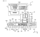
本実施形態1における工作物質量決定装置131、加工推定装置3b及び加工システム1について図1を参照して説明する。加工システム1は、研削加工を行う加工装置を対象とする。加工システム1は、加工装置としての研削盤2と、処理部3とを備える。
1.加工システム1の構成
本実施形態1における工作物質量決定装置131、加工推定装置3b及び加工システム1について図1を参照して説明する。加工システム1は、研削加工を行う加工装置を対象とする。加工システム1は、加工装置としての研削盤2と、処理部3とを備える。
研削盤2は、工作物Wを回転させ、回転体である工具としての砥石車Tを回転させ、かつ、砥石車Tを工作物Wに対して工作物Wの軸線に交差する方向に相対的に接近させることにより、工作物Wの外周面または内周面を研削する。研削盤2は、テーブルトラバース型の研削盤、砥石台トラバース型の研削盤などを適用可能である。また、研削盤2は、円筒研削盤、カム研削盤等を適用可能である。
本実施形態においては、図1に示すように、工作物Wは、非加工部としての軸部Waと、外周面が研削対象となる複数の加工部Wbとを備える場合を例にあげる。加工部Wbは、例えば、軸部Waと同軸の円筒外周面を有する。ただし、図1に示す工作物Wは、一例であって、研削盤2は、種々の形状を有する工作物を研削加工の対象とすることができる。
処理部3は、研削盤2を制御する制御装置3a、および、加工結果を推定する加工推定装置3bを備える。制御装置3aは、研削盤2を制御することにより、研削加工を制御することができる。加工推定装置3bは、研削加工に用いる情報を入力してシミュレーションを行うことにより、工作物Wにおける加工結果を推定する処理を行う。
加工推定装置3bは、研削盤2とは独立したシミュレーション装置として機能させることもできるし、研削盤2と連動して動作するシミュレーション装置として機能させることもできる。前者の場合には、例えば、実際の工作物Wの研削加工を行うことなく、最適な研削加工条件を決定することができる。後者の場合には、加工推定装置3bは、研削盤2による工作物Wの研削加工と並行して処理することにより、例えば、研削加工条件を補正したり、各種制御に影響を及ぼすように動作したりすることができる。また、加工推定装置3bは、研削盤2および制御装置3aの組込みシステムとすることもできる。
2.研削盤2および制御装置3aの構成
研削盤2および制御装置3aの構成の一例について、図1を参照して詳細に説明する。研削盤2は、テーブルトラバース型の円筒研削盤を例にあげる。つまり、当該研削盤2は、工作物Wを工作物Wの軸線方向に移動させ、かつ、砥石車Tを工作物Wの軸線に交差する方向に移動させる構成である。また、本実施形態においては、研削盤2は、砥石車Tにより工作物Wの円筒外周面を研削する場合を例にあげる。
研削盤2および制御装置3aの構成の一例について、図1を参照して詳細に説明する。研削盤2は、テーブルトラバース型の円筒研削盤を例にあげる。つまり、当該研削盤2は、工作物Wを工作物Wの軸線方向に移動させ、かつ、砥石車Tを工作物Wの軸線に交差する方向に移動させる構成である。また、本実施形態においては、研削盤2は、砥石車Tにより工作物Wの円筒外周面を研削する場合を例にあげる。
研削盤2は、ベッド10、テーブル20、主軸装置30、心押装置40、砥石台50、定寸装置60、制御装置3aを備える。ベッド10は、設置面上に設置されている。ベッド10は、X軸方向の正面側(図1の下側)の幅(Z軸方向長さ)が長く形成されており、X軸方向の背面側(図1の上側)の幅が短く形成されている。
ベッド10は、X軸方向の正面側の上面に、Z軸方向に延在するZ軸案内面11を備える。さらに、ベッド10には、Z軸案内面11に沿って駆動するZ軸駆動機構12を備える。本実施形態では、Z軸駆動機構12は、ボールねじ機構12aとZ軸用モータ12bとを備える場合を例にあげる。ボールねじ機構12aが、Z軸案内面11に平行に延在し、Z軸用モータ12bが、ボールねじ機構12aを駆動する。
Z軸駆動機構12を駆動するために、図示しないZ軸用駆動回路およびZ軸用検出器12cが設けられる。Z軸用駆動回路は、アンプ回路を含み、Z軸用モータ12bを駆動する。Z軸用検出器12cは、本実施形態においては、例えば、エンコーダなどの角度検出器であって、Z軸用モータ12bの回転軸の角度を検出する。なお、Z軸駆動機構12は、上記のボールねじ機構12aを備える構成に代えて、リニアモータなどを適用することもできる。
また、ベッド10は、X軸方向の背面側の上面に、Z軸方向に交差する方向に延在する案内面13を備える。本実施形態においては、案内面13は、Z軸に直交するX軸方向に延在するX軸案内面である。さらに、ベッド10には、X軸案内面13に沿って駆動するX軸駆動機構14を備える。本実施形態では、X軸駆動機構14は、ボールねじ機構14aとX軸用モータ14bとを備える場合を例にあげる。ボールねじ機構14aが、X軸案内面13に平行に延在し、X軸用モータ14bが、ボールねじ機構14aを駆動する。
X軸駆動機構14を駆動するために、図示しないX軸用駆動回路およびX軸用検出器14cが設けられる。X軸用駆動回路は、アンプ回路を含み、X軸用モータ14bを駆動する。X軸用検出器14cは、本実施形態においては、例えば、エンコーダなどの角度検出器であって、X軸用モータ14bの回転軸の角度を検出する。なお、X軸駆動機構14は、上記のボールねじ機構14aを備える構成に代えて、リニアモータなどを適用することもできる。
テーブル20は、長尺状に形成されており、ベッド10のZ軸案内面11にZ軸方向(水平左右方向)に移動可能に支持されている。また、テーブル20は、Z軸ボールねじ機構12aのボールねじナットに固定されており、Z軸用モータ12bの回転駆動によってZ軸方向に移動する。
主軸装置30は、工作物支持装置を構成する。主軸装置30は、工作物Wを支持し、工作物Wを回転駆動する。主軸装置30は、テーブル20上のZ軸方向の一端側に配置されている。主軸装置30は、主軸ハウジング31と、主軸32、主軸用モータ33と、主軸センタ34と、主軸用検出器35と、図示しない主軸用駆動回路とを備える。
主軸ハウジング31は、テーブル20上に固定されている。主軸32は、主軸ハウジング31に軸受を介して回転可能に支持される。主軸用モータ33は、主軸32を回転駆動する。主軸センタ34は、工作物Wの軸方向一端の端面を支持する。主軸センタ34は、主軸32に固定されて、主軸ハウジング31に対して回転可能に設けられる。ただし、主軸装置30が、図示しないケレなどの回し部材を備える場合には、主軸センタ34は、主軸ハウジング31に固定されて、主軸ハウジング31に対して回転不能となるように設けられるようにしても良い。また、主軸装置30は、主軸センタ34に代えて、工作物Wを把持するチャックを備えるようにしても良い。なお、チャックは、主軸32に連結されることで回転駆動される。
主軸用検出器35および主軸用駆動回路は、主軸用モータ33を駆動するために設けられている。主軸用検出器35は、本実施形態においては、例えば、エンコーダなどの角度検出器であって、主軸用モータ33の回転軸の角度を検出する。主軸用駆動回路は、アンプ回路を含み、主軸用モータ33を駆動する。
心押装置40は、主軸装置30と共に、工作物支持装置を構成する。心押装置40は、テーブル20上のZ軸方向の他端側に配置されている。心押装置40は、テーブル20上をZ軸方向に移動可能に設けられている。心押装置40は、心押センタ41を備える。心押センタ41は、工作物Wの軸方向他端の端面を支持する。心押センタ41は、回転不能に設けられるようにしても良いし、回転可能に設けられるようにしても良い。なお、研削盤2が、工作物Wの内周面を研削加工する場合には、心押装置40は不要である。
また、心押センタ41は、工作物Wに対して固定された位置に位置決めされるようにしても良いし、工作物Wに対して工作物Wの軸方向に動作可能に設けられるようにしても良い。後者において、心押センタ41は、工作物Wに対して工作物Wの軸方向への押圧力を調整可能に構成されるようにしても良い。押圧力は、スプリング力を調整する手段、流体圧を調整する手段などにより制御可能とすることができる。
砥石台50は、工具としての砥石車Tを備え、砥石車Tを回転駆動する。砥石台50は、砥石車Tの他に、砥石台本体51、砥石軸52、砥石車用モータ53、図示しない砥石車用駆動回路を備える。
砥石車Tは、円盤状に形成されている。砥石車Tは、工作物Wの外周面または内周面を研削するために用いられる。砥石車Tは、複数の砥粒を結合剤により固定されて構成されている。砥粒には、アルミナや炭化ケイ素などのセラミックス質の材料などにより形成される一般砥粒、ダイヤモンドやCBNなどの超砥粒などが適用される。
結合剤には、ビトリファイド(V)、レジノイド(B)、ラバー(R)、シリケート(S)、シェラック(E)、メタル(M)、電着(P)、マグネシアセメント(Mg)などが存在する。さらに、砥石車Tは、気孔を有する構成と、気孔を有しない構成とがある。砥石車Tは、結合剤の種類や気孔の有無によって、弾性変形可能な構成である場合と、ほぼ弾性変形しない構成である場合とが存在する。弾性変形可能な砥石車Tにおいて、結合剤の種類、気孔の有無、気孔率などによって、弾性率が異なる。
砥石台本体51は、例えば平面視にて矩形状に形成されており、ベッド10のX軸案内面13にX軸方向(水平前後方向)に移動可能に支持されている。また、砥石台本体51は、X軸ボールねじ機構14aのボールねじナットに固定されており、X軸用モータ14bの回転駆動によってX軸方向に移動する。砥石台本体51は、砥石車Tを支持する工具支持装置を構成する。
砥石軸52は、砥石台本体51に軸受を介して回転可能に支持される。砥石軸52の先端に砥石車Tが固定されており、砥石軸52の回転によって砥石車Tが回転する。砥石車用モータ53は、砥石軸52を回転駆動する。軸受には、静圧軸受や転がり軸受などが用いられる。
砥石車用モータ53は、例えば、ベルトを介して砥石軸52に回転駆動力を伝達する。ただし、砥石車用モータ53は、砥石軸52と同軸に配置しても良い。一般に、砥石車用モータ53の駆動による砥石車Tの回転速度は、主軸用モータ33の駆動による工作物Wの回転速度に比べて高速である。砥石車用駆動回路は、砥石車用モータ53を駆動するために設けられている。砥石車用駆動回路は、アンプ回路を含み、砥石車用モータ53を駆動する。
定寸装置60は、ベッド10の上面に設けられ、工作物Wの外径寸法を計測する。定寸装置60は、例えば、工作物Wの外周面に接触可能な一対の接触子を備えており、工作物Wへの接触部位における外径寸法を計測する。
制御装置3aは、加工制御を実行するCNC(Computer Numerical Control)装置およびPLC(Programmable Logic Controller)装置である。つまり、制御装置3aは、研削加工プログラムおよび定寸装置60による計測結果に基づいて、移動装置としてのZ軸駆動機構12およびX軸駆動機構14を駆動して、テーブル20および砥石台50の位置制御を行う。つまり、制御装置3aは、テーブル20および砥石台50などの位置制御を行うことで、工作物Wと砥石車Tとを相対的に接近および離間させる。さらに、制御装置3aは、主軸装置30および砥石台50の制御を行う。つまり、制御装置3aは、主軸32の回転制御および砥石車Tの回転制御を行う。
3.加工推定装置3bの構成
加工推定装置3bの構成について図2を参照して説明する。加工推定装置3bは、指令値取得部101、推定部102、接触動剛性テーブル記憶部(第2対応関係記憶部)103a、工作物質量テーブル記憶部(第1対応関係記憶部)103b、工作物支持動剛性テーブル記憶部103c、工具支持動剛性テーブル記憶部103d、加工条件取得部106、動特性決定部107、補正量算出部108、出力部109、加工条件最適化部110を備える。
加工推定装置3bの構成について図2を参照して説明する。加工推定装置3bは、指令値取得部101、推定部102、接触動剛性テーブル記憶部(第2対応関係記憶部)103a、工作物質量テーブル記憶部(第1対応関係記憶部)103b、工作物支持動剛性テーブル記憶部103c、工具支持動剛性テーブル記憶部103d、加工条件取得部106、動特性決定部107、補正量算出部108、出力部109、加工条件最適化部110を備える。
指令値取得部101は、研削加工において研削盤2を制御するための指令値を取得する。加工推定装置3bが、研削盤2とは独立したシミュレーション装置である場合には、指令値取得部101は、研削加工プログラムおよび研削盤2の構成情報を入力することにより、研削盤2の各部を制御するための指令値を演算により生成する。また、加工推定装置3bが、研削盤2による研削加工と連動して動作するシミュレーション装置として機能する場合には、指令値取得部101は、研削盤2の制御装置3aから直接指令値を取得することができる。
推定部102は、指令値取得部101が取得した指令値を用いて、研削加工シミュレーションを実行することにより、研削加工時における工作物Wまたは砥石車Tの状態、工作物Wの形状、砥石車Tの形状、および、研削盤2の機械状態の少なくとも1つを推定する。
工作物Wの状態は、例えば、工作物Wの振動状態や温度状態などを含む。砥石車Tの状態は、例えば、砥石車Tの振動状態や温度状態、砥石車Tの外周面の部位毎に生じた研削抵抗、砥石車Tの切れ味、砥石車Tを構成する砥粒の状態などを含む。砥粒の状態は、例えば、砥粒の平均突き出し量や砥粒分布などを含む。工作物Wの形状は、研削加工の途中段階の形状、研削加工の終了段階の形状を含む。砥石車Tの形状は、研削加工の途中段階の形状、研削加工の終了段階の形状を含む。研削盤2の機械状態は、研削盤2を構成する部位の振動状態や温度状態などを含む。
本実施形態においては、推定部102は、研削加工シミュレーションにより、工作物Wの形状が逐次変化する処理を行うことで、工作物Wの形状、工作物Wの状態、研削盤2の機械状態を推定対象とする場合を例にあげる。本実施形態においては、砥石車Tは変形しないものとして、研削加工シミュレーションを行う。なお、推定部102は、上記推定対象に加えて、砥石車Tの外周面の部位毎に生じた研削抵抗を推定することもできる。
推定部102は、干渉量算出部111、研削能率算出部112、研削特性決定部113、研削抵抗算出部114を備える。
干渉量算出部111は、指令値取得部101が取得した指令値を用いて得られた工作物Wと砥石車Tとの相対位置、工作物Wの外周面形状、および、砥石車Tの外周面形状に基づいて、工作物Wと砥石車Tとの干渉量を算出する。干渉量は、工作物Wの周方向の各部位における工作物Wの径方向の研削量に相当する。換言すると、干渉量は、砥石車Tにより研削される工作物Wの除去量、詳細には、工作物Wの周方向の各部位における工作物Wの径方向の除去量である。干渉量は、図3に示すように、工作物Wと砥石車Tとが干渉する部分(図3の斜線部分:干渉領域)の体積である。
干渉量算出部111は、当該干渉量を演算処理によって幾何学的に算出する。ここで、干渉量算出部111は、工作物Wの外周面形状、および、砥石車Tの外周面形状を記憶している。図4の右側部分に示すように、工作物Wの外周面形状は、工作物Wの回転中心Owを原点とした極座標上において、複数の径方向の線分群で表現されている。つまり、干渉量算出部111は、工作物Wを等角(α)に分割した外周面上の分割点(図4の白色点)と工作物Wの回転中心Ow(原点)とを結ぶ複数の線分群を、工作物Wの外周面形状として記憶している。図4における白色点にて示す分割点が、砥石車Tによる除去される前の工作物Wの外周面形状として記憶される。
干渉量算出部111は、工作物Wと砥石車Tとの相対位置(軸間距離)および砥石車Tの外周面形状から、工作物Wの各線分と砥石車Tの外周面形状を表す線との交点(図4の黒色点)を決定する。干渉量算出部111は、決定された交点(図4の黒色点)を、砥石車Tにより工作物Wの除去された後の工作物Wの外周面形状として記憶する。つまり、干渉量算出部111は、記憶している工作物Wの外周面形状を変更する。
そして、干渉量算出部111は、除去前の工作物Wの外周面形状を定義する点のうち隣り合う点a1、a2と原点Owとからなる三角形△Ow-a1-a2の面積から、除去後の点b1、b2(砥石車Tとの交点)と原点Owとからなる三角形△Ow-b1-b2の面積を減算する。減算後の面積を、工作物Wの外周面形状を定義する全ての隣り合う点について算出する。
そして、干渉量算出部111は、各減算後の面積を積算し、積算した総和面積に工作物Wの厚みを掛けて干渉量(除去量)を算出する。なお、上記においては、2種類の三角形の面積を算出して、その面積の差分を算出することにより、除去される部分の面積を算出した。この他に、四角形a1-a2-b1-b2を直接算出することにより、除去される部分の面積を算出してもよい。
図2に示すように、研削能率算出部112は、干渉量算出部111により算出された干渉量に基づいて、研削能率(加工能率)Z’を算出する。研削能率Z’は、単位時間当たりの干渉量、すなわち、単位時間において砥石車Tにより研削される工作物Wの体積を算出する。
研削特性決定部113は、工作物Wの材質、砥石車Tの砥粒や結合剤の種類、および、砥石車Tの外周面の状態などに基づいて、研削特性kcを決定する。砥石車Tの外周面の状態は、例えば、砥石車Tの砥粒の摩耗状態や切れ味を表す指標を用いて表現される。ここで、研削特性決定部113は、予め実験や解析などにより各状態における研削特性を記憶しておく。
研削抵抗算出部114は、研削能率Z’および研削特性kcに基づいて、工作物Wの外周面の法線方向(X軸方向)における研削抵抗Fnを算出する。研削抵抗Fnは、研削能率Z’に研削特性kcを乗算することにより得られる(Fn=kc×Z’)。
なお、研削特性kcは、研削能率Z’が大きくなるほど法線方向(X軸線方向)の研削抵抗Fnが大きくなるようなほぼ線形の関係を有する。そして、研削特性kcは、例えば、砥石車Tが摩耗した場合には、当該関係が変化する。例えば、砥石車Tが摩耗した場合には、研削能率Z’に対して、法線方向の研削抵抗Fnが大きくなるように変化する。
接触動剛性テーブル記憶部103aは、工作物Wと砥石車Tとの間の接触動剛性データ(Ci(Z’)、Ki(Z’))を記憶する。特に接触動剛性テーブル記憶部103aは、後述する加工状態指数と接触動剛性データ(Ci(Z’)、Ki(Z’))との対応関係を記憶する第2対応関係記憶部103aを構成する。工作物支持動剛性テーブル記憶部103cは、工作物支持装置としての主軸装置30および心押装置40における工作物支持動剛性データ(Cw、Kw)を記憶する。特に、工作物支持動剛性テーブル記憶部103cは、加工条件と工作物支持動剛性データ(Cw、Kw)との対応関係を記憶する。工具支持動剛性テーブル記憶部103dは、砥石車支持装置としての砥石台本体51における工具支持動剛性データ(Ct、Kt)を記憶する。特に、工具支持動剛性テーブル記憶部103dは、加工条件と工具支持動剛性データ(Ct、Kt)との対応関係を記憶する。
4.加工条件の取得
図2に示すように、加工条件取得部106は、研削盤2にて研削加工を行う際の加工条件を取得する。詳細には、加工条件取得部106は、推定部102による推定時(処理対象時)の加工条件を取得する。加工条件取得部106が取得する加工条件は、動特性決定部107が各動剛性を算出するために用いる情報である。取得する加工条件は、例えば、工作物Wの種類、工作物支持部材の種類、砥石車Tの種類、主軸センタ34及び心押センタ41による押圧力などである。
図2に示すように、加工条件取得部106は、研削盤2にて研削加工を行う際の加工条件を取得する。詳細には、加工条件取得部106は、推定部102による推定時(処理対象時)の加工条件を取得する。加工条件取得部106が取得する加工条件は、動特性決定部107が各動剛性を算出するために用いる情報である。取得する加工条件は、例えば、工作物Wの種類、工作物支持部材の種類、砥石車Tの種類、主軸センタ34及び心押センタ41による押圧力などである。
加工推定装置3bが、研削盤2とは独立したシミュレーション装置である場合には、加工条件取得部106は、研削盤2の機械構成および研削加工プログラムを入力することにより、動剛性を決定するための条件を取得する。また、加工推定装置3bが、研削盤2による研削加工と連動して動作するシミュレーション装置として機能する場合には、加工条件取得部106は、制御装置3aから研削盤2の機械構成および研削加工プログラムを入力することにより動剛性を決定するための条件を取得しても良いし、研削盤2の制御装置3aから直接条件に関する情報を取得しても良い。
5.動特性決定部107の構成
動特性決定部107は、研削加工に影響を及ぼす動剛性データ及び解析上の工作物質量(M’w(Z’))を決定する。動特性決定部107は、図5に示す、接触動剛性データ(Ci(Z’)、Ki(Z’))、工作物支持動剛性データ(Cw、Kw)および工具支持動剛性データ(Ct、Kt)と解析上の工作物質量(M’w(Z’))を、それぞれ別々に決定する。つまり、動特性決定部107は、接触動剛性決定部121、工作物質量決定部122、工作物支持動剛性決定部123、および、工具支持動剛性決定部124を備える。
動特性決定部107は、研削加工に影響を及ぼす動剛性データ及び解析上の工作物質量(M’w(Z’))を決定する。動特性決定部107は、図5に示す、接触動剛性データ(Ci(Z’)、Ki(Z’))、工作物支持動剛性データ(Cw、Kw)および工具支持動剛性データ(Ct、Kt)と解析上の工作物質量(M’w(Z’))を、それぞれ別々に決定する。つまり、動特性決定部107は、接触動剛性決定部121、工作物質量決定部122、工作物支持動剛性決定部123、および、工具支持動剛性決定部124を備える。
接触動剛性(Ci(Z’)、Ki(Z’))、工作物支持動剛性(Cw、Kw)、工具支持動剛性(Ct、Kt)および工作物質量(Mw)について、図5を参照して説明する。接触動剛性(Ci(Z’)、Ki(Z’))は、工作物Wと砥石車Tとの間の動剛性である。工作物支持動剛性(Cw、Kw)は、工作物Wを含み、テーブル20、主軸装置30及び装置40に関する工作物W側の動剛性である。また、工具支持動剛性(Ct、Kt)は、砥石車Tを含み、砥石台50に関する動剛性である。工作物質量(Mw)は、工作物Wの質量である。以下、それぞれについて詳述する。
5-1.接触動剛性、加工状態指数
接触動剛性は、工作物Wと砥石車Tとの間の動剛性であって、研削加工する際に工作物Wと砥石車Tとの接触により発揮する動剛性である。接触動剛性は、減衰係数Ciおよびばね定数Kiにより定義される。なお、接触動剛性と区別される接触静剛性は、ばね定数Kのみにより表され、減衰係数Cを含まない。接触動剛性における減衰係数Ciは、工作物Wと砥石車Tとの相対速度と、工作物Wまたは砥石車Tが受ける外力との関係を表す値である。ばね定数Kiは、工作物Wと砥石車Tとの相対位置と、工作物Wまたは砥石車Tが受ける外力との関係を表す値である。
接触動剛性は、工作物Wと砥石車Tとの間の動剛性であって、研削加工する際に工作物Wと砥石車Tとの接触により発揮する動剛性である。接触動剛性は、減衰係数Ciおよびばね定数Kiにより定義される。なお、接触動剛性と区別される接触静剛性は、ばね定数Kのみにより表され、減衰係数Cを含まない。接触動剛性における減衰係数Ciは、工作物Wと砥石車Tとの相対速度と、工作物Wまたは砥石車Tが受ける外力との関係を表す値である。ばね定数Kiは、工作物Wと砥石車Tとの相対位置と、工作物Wまたは砥石車Tが受ける外力との関係を表す値である。
そして、接触動剛性は、加工装置2において、研削加工する際に工具(砥石車T)による工作物Wの加工の状態に応じて変化する加工状態指数に対応する。加工状態指数は、例えば、加工能率(研削能率Z’)、接触弧長さL、g/a(砥粒切り込み深さ/砥粒切れ刃間隔)などを例示できる。加工状態指数と接触動剛性データ(Ci(Z’)、Ki(Z’))との対応関係である接触動剛性対応関係は、実測を行うことにより取得することができる。なお、接触弧長さLは、図3に示すように、砥石車Tの軸直交方向断面において、研削加工の際に砥石車Tの外周面のうち工作物Wに接触している円弧長さである。接触弧長さLは、砥石車TのX軸方向の送り速度、砥石車Tの外径、工作物Wの外径などにより変化する。
加工状態指数と接触動剛性データ(Ci(Z’)、Ki(Z’))との対応関係である接触動剛性対応関係の例を図6(a)及び(b)、図7(a)及び(b)に示す。図6(a)、(b)に示す例では、加工状態指数としての研削能率Z’を採用しており、研削能率Z’に対して、接触動剛性における減衰係数Ci及びばね定数Kiはいずれも、線形の関係(比例の関係)ではなく非線形の関係を有している。より詳細には、加工状態指数と接触動剛性データ(Ci(Z’)、Ki(Z’))との接触動剛性対応関係は、加工状態指数に対する接触動剛性データ(Ci(Z’)、Ki(Z’))の変化度合いが変動する関係となっており、例えば、横軸を加工状態指数とし、縦軸を接触動剛性データ(CiまたはKi)とした二次平面において、傾きが連続的に変化する曲線を表す関数を近似式として規定することができる。当該近似式は、高次関数とすることができ、例えば、図6(a)、(b)に示した曲線は3次関数で規定される曲線である。
図7(a)及び(b)に示す例では、加工状態指数として接触弧長さLを採用している。この場合は、加工状態指数を研削能率Z’とした場合と概ね同様の傾向を示すが、加工状態指数を研削能率Z’とした場合に比べて3次関数で表す曲線に適合しにくい傾向がある。一方、図6(a)、(b)に示すように加工状態指数を研削能率とした場合には、3次関数で表す曲線に適合しやすく、近似式の作成が容易となるため、加工状態指数として研削能率Z’を使用することが好ましい。なお、加工状態指数をg/aとした場合においても、加工状態指数と接触動剛性データ(Ci(Z’)、Ki(Z’))との対応関係は図6(a)、(b)に示す研削能率Z’の場合と概ね同様の傾向を示す。なお、接触動剛性対応関係は、上記曲線に替えて、上記二次平面において複数の直線をつなぎ合わせたものであってもよい。また、上記接触動剛性対応関係は近似式などの関数として規定されることに替えて、複数のデータの対応関係からなるデータテーブルの形式であってもよい。
加工状態指数は、接触動剛性決定部121に備えられた加工状態指数取得部125により取得され、加工状態指数と接触動剛性データ(Ci(Z’)、Ki(Z’))との対応関係である接触動剛性対応関係は、第2対応関係記憶部103aに記憶されている。そして、接触動剛性データ(Ci(Z’)、Ki(Z’))は、加工状態指数取得部125により取得された加工状態指数に基づいて、接触動剛性決定部121により決定される。すなわち、加工状態指数取得部125、第2対応関係記憶部103a及び接触動剛性決定部121により、接触動剛性決定装置130が構成される。
5-2.接触動剛性対応関係作成のための接触動剛性取得処理
上述の接触動剛性対応関係を作成するための接触動剛性の取得処理について、図8~図10を参照して説明する。図8に示すように、接触動剛性取得処理は、まず、測定治具4を研削盤2および工作物Wに取り付ける(S1)。測定治具4は、非接触加振器であって、工作物Wに加振力を付与する装置である。図9に示すように、測定治具4は、テーブル20の上面に設けられる。測定治具4は、テーブル20の上面においてZ軸方向の固定位置を調整可能である。
上述の接触動剛性対応関係を作成するための接触動剛性の取得処理について、図8~図10を参照して説明する。図8に示すように、接触動剛性取得処理は、まず、測定治具4を研削盤2および工作物Wに取り付ける(S1)。測定治具4は、非接触加振器であって、工作物Wに加振力を付与する装置である。図9に示すように、測定治具4は、テーブル20の上面に設けられる。測定治具4は、テーブル20の上面においてZ軸方向の固定位置を調整可能である。
測定治具4は、工作物Wを挿通させた状態で工作物Wを保持する。詳細には、測定治具4には、工作物Wの非加工部としての軸部Waの一部が挿通されており、研削対象となる複数の加工部Wbが測定治具4の外部に位置する。測定治具4に挿入されて保持された工作物Wは、通常の研削加工時と同様に、主軸装置30および心押装置40により支持される。
ここで、測定治具4の構成について、図10(a)~図10(c)を参照して説明する。測定治具4は、ハウジング131、電磁石132、ロータ133、ロックナット134、変位センサ135、制御装置136を備える。ハウジング131は、研削盤2のテーブル20の上面に固定される。さらに、ハウジング131は、Z軸方向に貫通する孔131aが形成されている。
電磁石132は、ハウジング131に埋設されている。ロータ133は、工作物Wの外周面に装着され、工作物Wに一体的に設けられる。ロータ133は、磁性体により形成されており、電磁石132により発生される磁力によって移動する。ロータ133は、円筒状に形成されており、ロータ133の外周面は、ハウジング131の内周面に対して所定の隙間を有して配置される。この隙間が、ロータ133がハウジング131に対して移動可能な距離となる。ロータ133の内周面は、工作物Wの外周面形状に応じて形成されている。ロックナット134は、ロータ133を工作物Wに固定するための部材である。ロータ133の固定方法は、ロックナット134を用いた手段に限らず、種々の手段を採用できる。
変位センサ135は、ハウジング131の内周面寄りの位置に設けられており、ロータ133の外周面との距離を測定する。つまり、変位センサ135は、電磁石132によりロータ133が加振された場合に、ロータ133がハウジング131の内周面に対して接近離間する方向のロータ133の変位(以下、径方向変位と称する)を測定する。
制御装置136は、図10(c)に示すように、電磁石132が加振力を付与するために電磁石132に対して駆動電流を供給する。また、制御装置136は、変位センサ135により測定された変位、すなわちロータ133の径方向変位を取得する。
そこで、図8のS1において、図10(a)に示すように、測定治具4のロータ133に、工作物Wの非加工部としての軸部Waを挿通する。そして、図10(b)に示すように、ロックナット134により工作物Wにロータ133を固定する。
そして、測定治具4のハウジング131をテーブル20に取り付ける。さらに、ロータ133が取り付けられた工作物Wを、主軸装置30および心押装置40により支持した状態とする。このとき、図10(b)に示すように、ロータ133の外周面が、測定治具4のハウジング131の内周面に対向する位置となるように、ハウジング131の位置を調整する。
続いて、研削加工を開始する(S2)。つまり、工作物Wおよび砥石車Tを回転させた状態で、砥石車TをX軸方向に移動して、工作物Wの加工部Wbの外周面を研削加工する。
続いて、測定治具4により加振力を付与する(S3)。測定治具4による加振力の付与は、砥石車Tにより工作物Wを研削加工しながら行われる。付与される加振力は、インパルス加振としても良いし、加振周波数を連続的に変化させるスイープ加振としても良い。加振力の付与は、測定治具4の制御装置136が電磁石132に電流を供給することにより行われる。そして、加振力は、制御装置136により電磁石132に供給される電流により制御される。
続いて、研削加工をしながら加振力を付与した際に、測定治具4の変位センサ135により、ロータ133の径方向変位を測定する(S4)。ここで、ロータ133の変位は、工作物Wにおいてロータ133に固定された部位の径方向変位に一致する。従って、測定治具4の変位センサ135は、工作物Wに加振力を付与した際に、工作物Wに生じる径方向変位を測定している。
続いて、変位センサ135による測定が終了した場合には、研削加工を終了する(S5)。
続いて、研削加工時における総合動剛性データ(Ccom、Kcom)を算出する(S6)。総合動剛性データ(Ccom、Kcom)とは、上述した接触動剛性データ(Ci(Z’)、Ki(Z’))、工作物支持動剛性データ(Cw、Kw)、および、工具支持動剛性データ(Ct、Kt)により表された総合的な(複合的な)動剛性データである。総合動剛性データ(Ccom、Kcom)は、上述した接触動剛性データ(Ci(Z’)、Ki(Z’))、工作物支持動剛性データ(Cw、Kw)、および、工具支持動剛性データ(Ct、Kt)の加算値として表される。
上述したように、測定治具4の変位センサ135により測定された径方向の変位は、研削加工しながら工作物Wに加振力を付与した際に測定される。従って、測定される変位は、接触動剛性データ(Ci(Z’)、Ki(Z’))、工作物支持動剛性データ(Cw、Kw)、工具支持動剛性データ(Ct、Kt)の影響を受けた状態である。そこで、総合動剛性データ(Ccom、Kcom)の算出は、研削加工しながら工作物Wに加振力を付与した際に、加振力と工作物Wの径方向変位との関係より生成されるデータとなる。
続いて、工作物支持動剛性データ(Cw、Kw)、および、工具支持動剛性データ(Ct、Kt)を取得する(S7)。工作物支持動剛性データ(Cw、Kw)および工具支持動剛性データ(Ct、Kt)は、予めハンマリング試験などにより取得されている。
続いて、接触動剛性データ(Ci(Z’)、Ki(Z’))を算出する(S8)。接触動剛性データ(Ci(Z’)、Ki(Z’))は、総合動剛性データ(Ccom、Kcom)から、工作物支持動剛性データ(Cw、Kw)および工具支持動剛性データ(Ct、Kt)を減算することにより求められる。
続いて、接触動剛性データ(Ci(Z’)、Ki(Z’))の補間処理を行う(S9)。補間処理は、実測により得られた接触動剛性データ(Ci、Ki)を用いて、実測とは異なる研削条件における接触動剛性データ(Ci(Z’)、Ki(Z’))を求める処理である。例えば、接触弧長さL、減衰係数Ciおよびばね定数Kiとの関係を定義した実験式を用いることができる。また、補間処理は、実験式、機械学習、理論計算などを適用することができる。このようにして、取得された接触動剛性データ(Ci(Z’)、Ki(Z’))を用いて、図6(a)、(b)に示す加工状態指数(研削能率)との接触動剛性対応関係を作成することができる。
5-3.工作物支持動剛性
工作物支持動剛性は、図1に示す主軸装置30および心押装置40における支持に関する動剛性であって、研削盤2を構成する工作物支持装置としての主軸装置30および心押装置40により工作物Wを支持する際に発揮する動剛性である。工作物支持動剛性は、図5に示すように、減衰係数Cwおよびばね定数Kwにより定義される。また、減衰係数Cwは、主軸装置30および心押装置40の基準位置に対する工作物Wの相対速度と、工作物Wが受ける外力との関係を表す値である。ばね定数Kwは、主軸装置30および心押装置40の基準位置に対する工作物Wの相対位置と、工作物Wが受ける外力との関係を表す値である。
工作物支持動剛性は、図1に示す主軸装置30および心押装置40における支持に関する動剛性であって、研削盤2を構成する工作物支持装置としての主軸装置30および心押装置40により工作物Wを支持する際に発揮する動剛性である。工作物支持動剛性は、図5に示すように、減衰係数Cwおよびばね定数Kwにより定義される。また、減衰係数Cwは、主軸装置30および心押装置40の基準位置に対する工作物Wの相対速度と、工作物Wが受ける外力との関係を表す値である。ばね定数Kwは、主軸装置30および心押装置40の基準位置に対する工作物Wの相対位置と、工作物Wが受ける外力との関係を表す値である。
また、上述したように、工作物支持動剛性データ(Cw、Kw)は、工作物支持動剛性テーブル記憶部103cにおいて、上述の加工条件に対応するように記憶されている。例えば、心押センタ41が工作物Wに対して工作物Wの軸方向への押圧力を制御可能な場合において、工作物支持動剛性データ(Cw、Kw)は、心押センタ41による押圧力の変化により心押センタ41と工作物Wとの接触状態が変化することに伴って変化するデータである。工作物支持動剛性データ(Cw、Kw)は、例えば、主軸センタ34および心押センタ41により工作物Wを支持した状態において、心押センタ41による押圧力を変化させてハンマリング試験を行うことにより取得できる。
そして、工作物支持動剛性決定部123により、工作物支持動剛性テーブル記憶部103cに記憶された工作物支持動剛性テーブルから、加工条件取得部106にて取得した加工条件に対応する工作物支持動剛性データ(Cw、Kw)を決定する。
5-4.工作物質量
解析上の工作物質量(M’w(Z’))は、解析上の工作物Wの質量であって、加工状態指数と相関する値である。そして、解析上の工作物質量(M’w(Z’))と加工状態指数との対応関係である質量対応関係が、第1対応関係記憶部としての工作物質量テーブル記憶部103bに記憶されている。質量対応関係における加工状態指数は、上述接触動剛性対応関係の場合と同様とすることができる。
解析上の工作物質量(M’w(Z’))は、解析上の工作物Wの質量であって、加工状態指数と相関する値である。そして、解析上の工作物質量(M’w(Z’))と加工状態指数との対応関係である質量対応関係が、第1対応関係記憶部としての工作物質量テーブル記憶部103bに記憶されている。質量対応関係における加工状態指数は、上述接触動剛性対応関係の場合と同様とすることができる。
加工状態指数と解析上の工作物質量(M’w(Z’))との対応関係である質量対応関係の例を図11に示す。図11に示すように、加工状態指数としての研削能率Z’に対して、解析上の工作物質量(M’w(Z’))は、線形の関係(比例の関係)ではなく非線形の関係を有している。より詳細には、加工状態指数と解析上の工作物質量(M’w(Z’))との対応関係である質量対応関係は、加工状態指数に対する解析上の工作物質量(M’w(Z’))の変化度合いが変動する関係となっており、例えば、横軸を加工状態指数とし、縦軸を解析上の工作物質量(M’w(Z’))とした二次平面において、傾きが連続的に変化する曲線を表す関数を近似式として規定することができる。当該近似式は、高次関数とすることができ、例えば、図11に示した曲線は3次関数で規定される曲線である。なお、上記質量対応関係は、上記曲線に替えて、上記二次平面において複数の直線をつなぎ合わせたものであってもよい。また、上記質量対応関係は近似式などの関数として規定されることに替えて、複数のデータの対応関係からなるデータテーブルの形式であってもよい。
図11には加工状態指数を研削能率Z’とした場合を示したが、加工状態指数を接触弧長さL又はg/aとした場合においても、加工状態指数と解析上の工作物質量(M’w(Z’))との質量対応関係は図11に示す研削能率Z’の場合と概ね同様の傾向を示すが、接触動剛性対応関係の場合と同様に、加工状態指数を研削能率Z’とすることが好ましい。
加工状態指数は、加工状態指数取得部125により取得され、加工状態指数と解析上の工作物質量(M’w(Z’))との対応関係である質量対応関係は、第1対応関係記憶部103bに記憶されている。そして、解析上の工作物質量(M’w(Z’))は、加工状態指数取得部125により取得された加工状態指数に基づいて、工作物質量決定部122により決定される。すなわち、加工状態指数取得部125、第1対応関係記憶部103b及び工作物質量決定部122により、工作物質量決定装置131が構成される。
5-5.質量対応関係作成のための解析上の工作物質量取得処理
質量対応関係における解析上の工作物質量(M’w(Z’))は、非加工時の工作物動特性(Mw、Cw、Kw)と接触動剛性データ(Ci(Z’)、Ki(Z’))とに基づいて、作成される。当該質量対応関係を作成するための工作物質量取得処理について、図12に示すフロー図に従って、以下に説明する。
質量対応関係における解析上の工作物質量(M’w(Z’))は、非加工時の工作物動特性(Mw、Cw、Kw)と接触動剛性データ(Ci(Z’)、Ki(Z’))とに基づいて、作成される。当該質量対応関係を作成するための工作物質量取得処理について、図12に示すフロー図に従って、以下に説明する。
まず、図12に示すステップS11において、図8に示す工程により、研削能率Z’を変化させた複数の態様のそれぞれにおいて、加振装置4を用いて変位センサ135の検出位置Weでの加工中の動特性を実測する。なお、このとき、研削能率Z’を変化させているため、研削抵抗は研削能率Z’に相関して変化するので、研削抵抗はFn(Z’)と表すことができる。
次いで、ステップS12において、変位センサ135の検出位置Weでの非加工中の動特性(Mw、Cw、Kw)を解析する。当該動特性は、例えば、非加工中のハンマリング試験での実測値を用いて、初期動特性(初期質量Mw、Cw、Kw)とする。
その後、ステップS13において、変位センサ135の検出位置Weでの非加工中の動特性(初期質量Mw、Cw、Kw)が、変位センサ135の検出位置Weでの複数の研削能率Z’のそれぞれの加工中の動特性に合うように、接触動剛性データ(Ci(Z’)、Ki(Z’))を同定する。具体的には、ステップS13では、初期質量Mw、Cw、Kwは固定パラメータとし、Ci(Z’)、Ki(Z’)を可変パラメータとして、非加工中の動特性(初期質量Mw、Cw、Kw)に接触動剛性データ(Ci(Z’)、Ki(Z’))を追加した解析モデルとして、解析モデルの動特性(初期質量Mw、Cw、Kw、Ci(Z’)、Ki(Z’))が複数の研削能率Z’のそれぞれの加工中の動特性に合うように、接触動剛性データ(Ci(Z’)、Ki(Z’))を同定する。
ここで、解析モデルの動特性(Mw、Cw、Kw、Ci(Z’)、Ki(Z’))を用いた加振力周波数-コンプライアンス特性が、実測値である複数の研削能率Z’のそれぞれの加工中の加振力周波数-コンプライアンス特性に完全には一致しないことが判明した。そこで、解析モデルの動特性のうち、工作物質量Mwを可変パラメータである修正工作物質量M’w(Z’)として、解析モデルの動特性が複数の研削能率Z’のそれぞれの加工中の動特性に合うように、加工点位置Wbでの解析上の修正工作物質量(M’w(Z’))の同定処理を行った。
つまり、ステップS14において、解析モデルの動特性を(M’w(Z’)、Cw、Kw、Ci(Z’)、Ki(Z’))で定義して、Cw、Kw、Ci(Z’)及びKi(Z’)を固定パラメータとし、M’w(Z’)を可変パラメータとする。そして、解析モデルの動特性が複数の研削能率Z’のそれぞれの加工中の動特性に合うように、加工点位置での解析上の修正工作物質量(M’w(Z’))を求める。
そして、解析上の修正工作物質量(M’w(Z’))は、運動方程式に基づいて、下記の式(1)で表される。
式(1)の通り、解析上の工作物質量(M’w(Z’))は加工能率(研削能率)Z’に相関し、接触動剛性データ(Ci(Z’)、Ki(Z’))もまた加工能率(研削能率)Z’に相関する。
なお、本実施形態では、変位センサ135の検出位置Weと加工点位置Wbとが異なる位置としたが、両者の位置が一致していてもよい。
5-6.工具支持動剛性
工具支持動剛性は、図1に示す砥石台本体51における支持に関する動剛性であって、研削盤2を構成する砥石車支持装置としての砥石台本体51により砥石車Tを支持する際に発揮する動剛性である。工具支持動剛性は、図5に示すように、減衰係数Ctおよびばね定数Ktにより定義される。減衰係数Ctは、砥石台本体51における基準位置に対する砥石車Tの相対速度と、砥石車Tが受ける外力との関係を表す値である。ばね定数Ktは、砥石台本体51における基準位置に対する砥石車Tの相対位置と、砥石車Tが受ける外力との関係を表す値である。
工具支持動剛性は、図1に示す砥石台本体51における支持に関する動剛性であって、研削盤2を構成する砥石車支持装置としての砥石台本体51により砥石車Tを支持する際に発揮する動剛性である。工具支持動剛性は、図5に示すように、減衰係数Ctおよびばね定数Ktにより定義される。減衰係数Ctは、砥石台本体51における基準位置に対する砥石車Tの相対速度と、砥石車Tが受ける外力との関係を表す値である。ばね定数Ktは、砥石台本体51における基準位置に対する砥石車Tの相対位置と、砥石車Tが受ける外力との関係を表す値である。
上述したように、工具支持動剛性データ(Ct、Kt)は、工具支持動剛性テーブル記憶部103dにおいて、上述の加工条件に対応するように記憶されている。工具支持動剛性テーブル記憶部103dは、例えば、砥石車Tの種類毎に、工具支持動剛性データ(Ct、Kt)を記憶する。また、砥石車Tが静圧軸受により支持される構成において、静圧軸受の圧力を制御可能な場合において、工具支持動剛性データ(Ct、Kt)が、加工条件に応じて変化する場合は、工具支持動剛性テーブル記憶部103dは、加工条件と、工具支持動剛性データ(Ct、Kt)との対応関係を記憶するようにしても良い。
そして、工具支持動剛性決定部124により、工具支持動剛性テーブル記憶部103dに記憶された工具支持動剛性テーブルから、加工条件取得部106にて取得した加工条件に対応する工具支持動剛性データ(Cw、Kw)を決定する。なお、工具Tにおける工具質量Msは運動方程式に基づいて、下記の式(2)で表される。
6.補正量算出部108
補正量算出部108は、研削抵抗に起因して砥石車Tおよび工作物WがX軸線方向に相対変位する補正量を、動特性決定部107にて決定された各動剛性データ及び解析上の工作物質量(M’w(Z’))に基づいて算出する。変位に関する補正量は、各動剛性データ及び解析上の工作物質量(M’w(Z’))と研削抵抗から求めることができる。つまり、変位に関する補正量は、研削抵抗、接触動剛性データ(Ci(Z’)、Ki(Z’))、工作物支持動剛性データ(Cw、Kw)、工具支持動剛性データ(Ct、Kt)及び解析上の工作物質量(M’w(Z’))から算出することができる。
補正量算出部108は、研削抵抗に起因して砥石車Tおよび工作物WがX軸線方向に相対変位する補正量を、動特性決定部107にて決定された各動剛性データ及び解析上の工作物質量(M’w(Z’))に基づいて算出する。変位に関する補正量は、各動剛性データ及び解析上の工作物質量(M’w(Z’))と研削抵抗から求めることができる。つまり、変位に関する補正量は、研削抵抗、接触動剛性データ(Ci(Z’)、Ki(Z’))、工作物支持動剛性データ(Cw、Kw)、工具支持動剛性データ(Ct、Kt)及び解析上の工作物質量(M’w(Z’))から算出することができる。
補正量算出部108は、算出した補正量を、推定部102へ出力する。推定部102は、上述したように、指令値取得部101が取得した工作物Wと砥石車Tとの相対位置、工作物Wの外周面形状、および、砥石車Tの外周面形状に基づいて、推定対象を推定する。ただし、研削抵抗により、工作物Wと砥石車Tとの相対位置は、指令値による相対位置とは異なる位置となる。
そこで、推定部102、推定対象の推定の際に、工作物Wと砥石車Tとの相対位置として、指令値取得部101が取得した相対位置に加えて、補正量算出部108により算出された補正量を加えた相対位置を用いる。つまり、推定部102は、指令値による相対位置と、各動剛性データを用いて算出された補正量とに基づいて、推定対象を推定する。
特に、本実施形態1においては、補正量算出部108は、算出した補正量を、推定部102の干渉量算出部111へ出力する。干渉量算出部111は、上述したように、指令値取得部101が取得した工作物Wと砥石車Tとの相対位置、工作物Wの外周面形状、および、砥石車Tの外周面形状に基づいて、工作物Wと砥石車Tとの干渉量を算出する。ただし、研削抵抗により、工作物Wと砥石車Tとの相対位置は、指令値による相対位置とは異なる位置となる。
そこで、干渉量算出部111は、干渉量の算出に用いる工作物Wと砥石車Tとの相対位置として、指令値取得部101が取得した相対位置に加えて、補正量算出部108により算出された補正量を加えた相対位置を用いる。つまり、干渉量算出部111は、指令値による相対位置と、各動剛性データを用いて算出された補正量とに基づいて、干渉量を算出する。
干渉量算出部111が、補正量を考慮した干渉量を算出するため、研削能率算出部112、研削特性決定部113、研削抵抗算出部114は、補正量を考慮した干渉量に基づき得られた研削能率Z’、研削特性kc、研削抵抗Fnを得る。
出力部109は、推定部102により推定された推定対象を出力する。つまり、出力部109は、研削加工時における工作物Wまたは砥石車Tの状態、工作物Wの形状、砥石車Tの形状、および、加工システム1の機械状態(研削盤2の機械状態に相当)の少なくとも1つを推定する。出力部109は、例えば、図示しない教示装置に推定結果を教示するようにしても良い。
加工条件最適化部110は、推定部102による推定結果に基づいて加工条件を最適化する。そして、加工条件最適化部110は、最適化された加工条件を研削盤2の制御装置3aに出力することができる。この場合、制御装置3aは、最適化された加工条件を用いて、研削加工を行うことができる。この他に、制御装置3aは、推定結果によらず、動特性決定部107により決定された各種の動剛性データ及び解析上の工作物質量(M’w(Z’))を用いて、加工の制御を行うこともできる。
7.作用効果
本実施形態1の工作物質量決定装置131によれば、解析上の工作物質量(M’w(Z’))は、記憶された加工状態指数と解析上の工作物質量(M’w(Z’))との対応関係である質量対応関係と、取得された加工状態指数とに基づいて決定される。これにより、加工状態指数との対応関係に基づいて解析上の工作物質量(M’w(Z’))を高精度に決定することができる。
本実施形態1の工作物質量決定装置131によれば、解析上の工作物質量(M’w(Z’))は、記憶された加工状態指数と解析上の工作物質量(M’w(Z’))との対応関係である質量対応関係と、取得された加工状態指数とに基づいて決定される。これにより、加工状態指数との対応関係に基づいて解析上の工作物質量(M’w(Z’))を高精度に決定することができる。
そして、このようにして高精度に決定された解析上の工作物質量(M’w(Z’))は、加工する際に工作物Wと工具Tとの接触により発揮する工作物Wと工具Tとの間の接触動剛性データ(Ci(Z’)、Ki(Z’))とともに工作物Wの加工結果を推定することに用いれば、加工結果の推定の高精度化が期待できる。
また、本実施形態1の工作物質量決定装置131では、上記質量対応関係における解析上の工作物質量(M’w(Z’))は、非加工時の工作物動特性(Mw、Cw、Kw)と接触動剛性データ(Ci(Z’)、Ki(Z’))とに基づいて作成される。これにより、解析上の工作物質量(M’w(Z’))の変化をより正確に取得することができるため、解析上の工作物質量(M’w(Z’))を高精度に決定することができる。
また、本実施形態1の工作物質量決定装置131では、接触動剛性データ(Ci(Z’)、Ki(Z’))は、工具Tにより工作物Wを加工しながら工作物Wに加振力を付与した際に、当該加振力と工作物Wの変位との関係により生成されるデータである。これにより、接触動剛性データ(Ci(Z’)、Ki(Z’))は、工作物Wと砥石車Tとの間の動剛性を正確に表すものとなるため、解析上の工作物質量(M’w(Z’))を高精度に決定することができる。
また、本実施形態1の工作物質量決定装置131では、上記質量対応関係は、横軸を加工状態指数とし、縦軸を解析上の工作物質量とした二次平面において、傾きが連続的に変化する曲線を表す関数の近似式として規定される。このように、質量対応関係を非線形の関係である曲線を表す関数の近似式で規定することで、解析上の工作物質量の変化をより正確に取得することができるため、解析上の工作物質量(M’w(Z’))を高精度に決定することができる。
また、本実施形態1の工作物質量決定装置131では、加工状態指数は、工具Tによる工作物Wの加工能率である。加工能率は、工作物Wの加工状態に密接に関係しているため、加工状態指数として加工能率を用いることにより、工作物Wの加工状態に応じて解析上の工作物質量(M’w(Z’))を高精度に決定することができる。
また、本実施形態1の工作物質量決定装置131では、加工装置2は、工具である砥石車Tにより工作物Wの円筒外周面を研削加工する円筒研削盤であり、工作物Wの軸方向一端を支持すると共に回転駆動する主軸装置30、および、工作物Wの軸方向他端を支持する心押センタ41により構成される工作物支持装置を備える。そして、加工状態指数は、砥石車Tによる工作物Wの研削能率Z’である。これにより、加工状態指数を研削能率とすることで、解析上の工作物質量(M’w(Z’))が3次関数で表す曲線に適合しやすく、近似式の作成が容易となるとともに、より高精度に解析上の工作物質量(M’w(Z’))を決定することができる。
また、本実施形態1の工作物質量決定装置131では、加工装置2は、工具である砥石車Tにより工作物Wの円筒外周面を研削加工する円筒研削盤であり、工作物Wの軸方向一端を支持すると共に回転駆動する主軸装置30、および、工作物Wの軸方向他端を支持する心押センタ41により構成される工作物支持装置を備える。そして、加工状態指数は、砥石車Tにおける工作物Wとの接触弧長さLである。これにより、加工状態指数を容易に取得でき、計算負荷を低減することができる。
また、本実施形態1の加工推定装置3bは、工作物質量決定装置131を備え、加工装置2における工作物Wの加工結果を推定する。そして、加工状態指数(Z’)と接触動剛性データ(Ci(Z’)、Ki(Z’))との対応関係である接触動剛性対応関係を記憶する第2対応関係記憶部103aと、加工状態指数取得部125により取得された加工状態指数(Z’)と接触動剛性対応関係とに基づいて、接触動剛性データ(Ci(Z’)、Ki(Z’))を決定する接触動剛性決定部121と、接触動剛性決定部により決定された接触動剛性データ(Ci(Z’)、Ki(Z’))と、工作物質量決定部122により決定された解析上の工作物質量(M’w(Z’))とを用いて工作物Wの加工結果を推定する推定部102と、を備える。このように、解析上の工作物質量(M’w(Z’))を加工状態指数との対応関係に基づいて決定することにより、加工結果の推定に解析上の工作物質量(M’w(Z’))の変化が反映されるため、より高精度に加工結果を推定できる。
また、本実施形態1の加工推定装置3bでは、接触動剛性対応関係における接触動剛性データは、工具Tにより工作物Wを加工しながら工作物Wに加振力を付与した際に、当該加振力と工作物Wの変位との関係により生成されるデータである。これにより、接触動剛性データ(Ci(Z’)、Ki(Z’))は、工作物Wと砥石車Tとの間の動剛性を正確に表すものとなるため、より高精度に加工結果を推定できる。
また、本実施形態1の加工推定装置3bは、加工装置2を構成する工作物支持装置30、40により工作物Wを支持する際に発揮する工作物支持装置30、40における工作物支持動剛性データを決定する工作物支持動剛性決定部123と、加工装置2を構成する工具支持装置51により工具Tを支持する際に発揮する工具支持装置51における工具支持動剛性データを決定する工具支持動剛性決定部124と、接触動剛性データ(Ci(Z’)、Ki(Z’))、工具支持動剛性データ(Ct、Kt)、工作物支持動剛性データ(Cw、Kw)及び解析上の工作物質量(M’w(Z’))に基づいて、工具Tと工作物Wとの相対位置の補正量を算出する補正量算出部108とを備え、推定部102は、工作物Wの加工についての指令値と補正量とに基づいて、工具Tによる工作物Wの加工結果を推定する。これにより、加工推定装置3bは、工具Tと工作物Wとの相対位置の補正量を算出する際に、高精度に算出された解析上の工作物質量(M’w(Z’))を用いているため、工作物Wの加工結果を高精度に推定することができる。
また、本実施形態1の加工システム1では、加工推定装置3bは、推定部102により推定された加工結果に基づいて、工作物Wの加工条件を最適化する加工条件最適化部110をさらに備え、加工装置2は、最適化された加工条件に基づいて、工具Tにより工作物Wの加工を行うように構成されている。これにより、高精度に推定された加工結果に基づいて最適化された加工条件によって工作物Wの加工を行うことができるため、高精度の工作物Wの作成を安定して行うことができ、製造コストの低減を図ることができる。
以上のごとく、上記態様によれば、解析上の工作物質量を高精度に決定することができる工作物質量決定装置131、加工推定装置3b及び加工システム1を提供することができる。
本実施形態1の場合に替えて、図13に示す変形形態では、加工装置2がレスト装置70を備えている。レスト装置70は、図14に示すように、第1アーム71と第2アーム72を備えており、両アーム71、72により、工作物Wの下部W1と、工具Tと反対側部W2を滑り支持するように構成されている。レスト装置70は、工作物Wが加工の際に工具Tから離れるように変形することを防止する。
レスト装置70により工作物Wが支持されることで、加工点Waの動特性が変化するため、解析上の工作物質量(M’w(Z’))が変化することとなる。動特性決定部107はこれを考慮して動特性を決定することができる。この場合も本実施形態1の場合と同様の作用効果を奏することができる。なお、レスト装置70を有する場合には、工作物Wの支持は片持ち支持、両持ち支持のいずれでもよい。
上記実施形態においては、加工装置として研削盤2を用いた研削加工を用いた切削加工について例をあげて説明したが、これらの他に、旋盤やマシニングセンタを用いた切削加工についても同様に適用可能である。切削加工の場合には、加工状態指数として、切削能率、切込み深さ等を採用することができる。
Claims (11)
- 工具(T)により工作物(W)を加工する加工装置(2)において、加工中の動特性を解析するための解析上の工作物質量(M’w(Z’))を算出する工作物質量決定装置(131)であって、
上記工具による上記工作物の加工の状態に応じて変化する加工状態指数(Z’)と上記解析上の工作物質量(M’w(Z’))との対応関係である質量対応関係を記憶する第1対応関係記憶部(103b)と、
上記加工状態指数(Z’)を取得する加工状態指数取得部(125)と、
取得された上記加工状態指数(Z’)と上記質量対応関係とに基づいて、上記解析上の工作物質量(M’w(Z’))を決定する工作物質量決定部(122)と、を備える工作物質量決定装置。 - 上記質量対応関係における上記解析上の工作物質量(M’w(Z’))は、非加工時の工作物動剛性(Cw、Kw)と、加工する際に上記工作物と上記工具との接触により発揮する上記工作物と上記工具との間の接触動剛性データ(Ci(Z’)、Ki(Z’))とに基づいて作成される、請求項1に記載の工作物質量決定装置。
- 上記接触動剛性データは、上記工具により上記工作物を加工しながら上記工作物に加振力を付与した際に、上記加振力と上記工作物の変位との関係により生成されるデータである、請求項2に記載の加工推定装置。
- 上記質量対応関係は、横軸を上記加工状態指数とし、縦軸を上記解析上の工作物質量(M’w(Z’))とした二次平面において、傾きが連続的に変化する曲線を表す関数を近似式として規定される、請求項1~3のいずれか一項に記載の工作物質量決定装置。
- 上記加工状態指数は、上記工具による上記工作物の加工能率である、請求項1~3のいずれか一項に記載の工作物質量決定装置。
- 上記加工装置(2)は、上記工具である砥石車により上記工作物の円筒外周面を研削加工する円筒研削盤であり、上記工作物の軸方向一端を支持すると共に回転駆動する主軸装置(30)、および、上記工作物の軸方向他端を支持する心押センタ(41)により構成される工作物支持装置を備え、
上記加工状態指数は、上記砥石車による上記工作物の研削能率(Z’)である、請求項1~3のいずれか一項に記載の工作物質量決定装置。 - 上記加工装置(2)は、上記工具である砥石車により上記工作物の円筒外周面を研削加工する円筒研削盤であり、上記工作物の軸方向一端を支持すると共に回転駆動する主軸装置(30)、および、上記工作物の軸方向他端を支持する心押センタ(41)により構成される工作物支持装置を備え、
上記加工状態指数は、上記砥石車における上記工作物との接触弧長さ(L)である、請求項1~3のいずれか一項に記載の工作物質量決定装置。 - 請求項1に記載の上記工作物質量決定装置を備え、上記加工装置(2)における上記工作物(W)の加工結果を推定する加工推定装置(3b)であって、
上記加工状態指数(Z’)と、加工する際に上記工作物と上記工具との接触により発揮する上記工作物と上記工具との間の接触動剛性データ(Ci(Z’)、Ki(Z’))との対応関係である接触動剛性対応関係を記憶する第2対応関係記憶部(103a)と、
上記加工状態指数取得部により取得された上記加工状態指数(Z’)と上記接触動剛性対応関係とに基づいて、上記接触動剛性データ(Ci(Z’)、Ki(Z’))を決定する接触動剛性決定部(121)と、
上記接触動剛性決定部により決定された上記接触動剛性データ(Ci(Z’)、Ki(Z’))と、上記工作物質量決定部により決定された上記解析上の工作物質量(M’w(Z’))とを用いて上記工作物の加工結果を推定する推定部(102)と、を備える加工推定装置。 - 上記接触動剛性対応関係における上記接触動剛性データは、上記工具により上記工作物を加工しながら上記工作物に加振力を付与した際に、上記加振力と上記工作物の変位との関係により生成されるデータである、請求項8に記載の加工推定装置。
- 上記加工装置を構成する工作物支持装置(30、40)により上記工作物を支持する際に発揮する上記工作物支持装置における工作物支持動剛性データを決定する工作物支持動剛性決定部(123)と、
上記加工装置を構成する工具支持装置(51)により上記工具を支持する際に発揮する上記工具支持装置における工具支持動剛性データを決定する工具支持動剛性決定部(124)と、
上記接触動剛性データ、上記工作物支持動剛性データ、上記工具支持動剛性データ及び上記解析上の工作物質量(M’w(Z’))に基づいて、上記工具と上記工作物との相対位置の補正量を算出する補正量算出部(108)と、をさらに備え、
上記推定部は、上記工作物の加工についての指令値と上記補正量とに基づいて、上記工具による上記工作物の加工結果を推定する、請求項8に記載の加工推定装置。 - 請求項8~10のいずれか一項に記載の加工推定装置であって、上記推定部により推定された加工結果に基づいて、上記工作物の加工条件を最適化する加工条件最適化部(110)をさらに備える上記加工推定装置と、
最適化された上記加工条件に基づいて、上記工具により上記工作物の加工を行う上記加工装置と、を備える加工システム(1)。
Priority Applications (1)
| Application Number | Priority Date | Filing Date | Title |
|---|---|---|---|
| PCT/JP2022/037724 WO2024075303A1 (ja) | 2022-10-07 | 2022-10-07 | 工作物質量決定装置、加工推定装置及び加工システム |
Applications Claiming Priority (1)
| Application Number | Priority Date | Filing Date | Title |
|---|---|---|---|
| PCT/JP2022/037724 WO2024075303A1 (ja) | 2022-10-07 | 2022-10-07 | 工作物質量決定装置、加工推定装置及び加工システム |
Publications (1)
| Publication Number | Publication Date |
|---|---|
| WO2024075303A1 true WO2024075303A1 (ja) | 2024-04-11 |
Family
ID=90608009
Family Applications (1)
| Application Number | Title | Priority Date | Filing Date |
|---|---|---|---|
| PCT/JP2022/037724 WO2024075303A1 (ja) | 2022-10-07 | 2022-10-07 | 工作物質量決定装置、加工推定装置及び加工システム |
Country Status (1)
| Country | Link |
|---|---|
| WO (1) | WO2024075303A1 (ja) |
Citations (5)
| Publication number | Priority date | Publication date | Assignee | Title |
|---|---|---|---|---|
| JP2005250985A (ja) * | 2004-03-05 | 2005-09-15 | Gunma Prefecture | 機械システムの診断方法及び機械システム診断装置 |
| JP2009064426A (ja) * | 2007-08-10 | 2009-03-26 | Jtekt Corp | びびりシミュレーション装置、および、びびりシミュレーション方法 |
| JP2015208812A (ja) * | 2014-04-25 | 2015-11-24 | 学校法人日本大学 | 研削加工装置及び方法 |
| CN105710782A (zh) * | 2016-04-01 | 2016-06-29 | 上海理工大学 | 基于时间常数的切入磨削接触刚度测量方法 |
| JP2018001301A (ja) * | 2016-06-28 | 2018-01-11 | 株式会社小松製作所 | 工作機械、加工物の製造方法、及び加工システム |
-
2022
- 2022-10-07 WO PCT/JP2022/037724 patent/WO2024075303A1/ja unknown
Patent Citations (5)
| Publication number | Priority date | Publication date | Assignee | Title |
|---|---|---|---|---|
| JP2005250985A (ja) * | 2004-03-05 | 2005-09-15 | Gunma Prefecture | 機械システムの診断方法及び機械システム診断装置 |
| JP2009064426A (ja) * | 2007-08-10 | 2009-03-26 | Jtekt Corp | びびりシミュレーション装置、および、びびりシミュレーション方法 |
| JP2015208812A (ja) * | 2014-04-25 | 2015-11-24 | 学校法人日本大学 | 研削加工装置及び方法 |
| CN105710782A (zh) * | 2016-04-01 | 2016-06-29 | 上海理工大学 | 基于时间常数的切入磨削接触刚度测量方法 |
| JP2018001301A (ja) * | 2016-06-28 | 2018-01-11 | 株式会社小松製作所 | 工作機械、加工物の製造方法、及び加工システム |
Similar Documents
| Publication | Publication Date | Title |
|---|---|---|
| JP6405098B2 (ja) | 研磨マシンのドレスツールのトポグラフィ偏差を特定する方法およびこれに対応して構成されたcnc制御マシン | |
| JP7305945B2 (ja) | 工作機械 | |
| JP2017037640A (ja) | 振動感知を用いる機械工具経路補正 | |
| JP2007175815A (ja) | 砥石車の修正方法及び修正装置 | |
| JP2007000945A (ja) | 研削方法及び装置 | |
| US6732009B2 (en) | Machining error correction method adapted for numerically controlled machine tool and grinding machine using the same | |
| Gallego | Intelligent centerless grinding: global solution for process instabilities and optimal cycle design | |
| JP7172636B2 (ja) | 工作機械のメンテナンス支援装置および工作機械システム | |
| WO2024075303A1 (ja) | 工作物質量決定装置、加工推定装置及び加工システム | |
| JP2008093788A (ja) | 研削盤 | |
| WO2024075284A1 (ja) | 接触動剛性算出システム、加工推定装置及び加工システム | |
| JP4940904B2 (ja) | かつぎ量計測装置 | |
| WO2023047437A1 (ja) | 加工推定装置 | |
| JP2020179432A (ja) | 研削方法及び研削盤 | |
| Gouarir et al. | In-process tool wear detection of uncoated square end mill based on electrical contact resistance | |
| JP2010274405A (ja) | 回転体の表面粗さの測定方法、砥石における砥粒の突き出し量の測定方法、及び研削盤 | |
| JP7451949B2 (ja) | 加工品質予測システム | |
| JP2019155557A (ja) | 工作機械の駆動軸の偏差の推定方法及びそれを用いた工作機械 | |
| JP2024087249A (ja) | 加工評価装置 | |
| JP2843488B2 (ja) | 工作機械の制御方法および制御装置 | |
| WO2023058107A1 (ja) | 加工装置 | |
| JP2021171833A (ja) | 表面粗さ推定システム | |
| JP2011088257A (ja) | 研削盤および研削方法 | |
| JP3627225B2 (ja) | 砥石車のツルーイング装置 | |
| JP2021074841A (ja) | 加工品質予測システム |
Legal Events
| Date | Code | Title | Description |
|---|---|---|---|
| 121 | Ep: the epo has been informed by wipo that ep was designated in this application |
Ref document number: 22961489 Country of ref document: EP Kind code of ref document: A1 |