WO2024018826A1 - ヒータ、定着装置、画像形成装置及び加熱装置 - Google Patents
ヒータ、定着装置、画像形成装置及び加熱装置 Download PDFInfo
- Publication number
- WO2024018826A1 WO2024018826A1 PCT/JP2023/023329 JP2023023329W WO2024018826A1 WO 2024018826 A1 WO2024018826 A1 WO 2024018826A1 JP 2023023329 W JP2023023329 W JP 2023023329W WO 2024018826 A1 WO2024018826 A1 WO 2024018826A1
- Authority
- WO
- WIPO (PCT)
- Prior art keywords
- heater
- wiring
- heat generating
- cells
- heating
- Prior art date
- Legal status (The legal status is an assumption and is not a legal conclusion. Google has not performed a legal analysis and makes no representation as to the accuracy of the status listed.)
- Ceased
Links
Images




Classifications
-
- H—ELECTRICITY
- H05—ELECTRIC TECHNIQUES NOT OTHERWISE PROVIDED FOR
- H05B—ELECTRIC HEATING; ELECTRIC LIGHT SOURCES NOT OTHERWISE PROVIDED FOR; CIRCUIT ARRANGEMENTS FOR ELECTRIC LIGHT SOURCES, IN GENERAL
- H05B3/00—Ohmic-resistance heating
- H05B3/0095—Heating devices in the form of rollers
-
- H—ELECTRICITY
- H05—ELECTRIC TECHNIQUES NOT OTHERWISE PROVIDED FOR
- H05B—ELECTRIC HEATING; ELECTRIC LIGHT SOURCES NOT OTHERWISE PROVIDED FOR; CIRCUIT ARRANGEMENTS FOR ELECTRIC LIGHT SOURCES, IN GENERAL
- H05B3/00—Ohmic-resistance heating
- H05B3/10—Heating elements characterised by the composition or nature of the materials or by the arrangement of the conductor
-
- G—PHYSICS
- G03—PHOTOGRAPHY; CINEMATOGRAPHY; ANALOGOUS TECHNIQUES USING WAVES OTHER THAN OPTICAL WAVES; ELECTROGRAPHY; HOLOGRAPHY
- G03G—ELECTROGRAPHY; ELECTROPHOTOGRAPHY; MAGNETOGRAPHY
- G03G15/00—Apparatus for electrographic processes using a charge pattern
- G03G15/20—Apparatus for electrographic processes using a charge pattern for fixing, e.g. by using heat
-
- G—PHYSICS
- G03—PHOTOGRAPHY; CINEMATOGRAPHY; ANALOGOUS TECHNIQUES USING WAVES OTHER THAN OPTICAL WAVES; ELECTROGRAPHY; HOLOGRAPHY
- G03G—ELECTROGRAPHY; ELECTROPHOTOGRAPHY; MAGNETOGRAPHY
- G03G15/00—Apparatus for electrographic processes using a charge pattern
- G03G15/20—Apparatus for electrographic processes using a charge pattern for fixing, e.g. by using heat
- G03G15/2003—Apparatus for electrographic processes using a charge pattern for fixing, e.g. by using heat using heat
- G03G15/2014—Apparatus for electrographic processes using a charge pattern for fixing, e.g. by using heat using heat using contact heat
- G03G15/2039—Apparatus for electrographic processes using a charge pattern for fixing, e.g. by using heat using heat using contact heat with means for controlling the fixing temperature
- G03G15/2042—Apparatus for electrographic processes using a charge pattern for fixing, e.g. by using heat using heat using contact heat with means for controlling the fixing temperature specially for the axial heat partition
-
- G—PHYSICS
- G03—PHOTOGRAPHY; CINEMATOGRAPHY; ANALOGOUS TECHNIQUES USING WAVES OTHER THAN OPTICAL WAVES; ELECTROGRAPHY; HOLOGRAPHY
- G03G—ELECTROGRAPHY; ELECTROPHOTOGRAPHY; MAGNETOGRAPHY
- G03G15/00—Apparatus for electrographic processes using a charge pattern
- G03G15/20—Apparatus for electrographic processes using a charge pattern for fixing, e.g. by using heat
- G03G15/2003—Apparatus for electrographic processes using a charge pattern for fixing, e.g. by using heat using heat
- G03G15/2014—Apparatus for electrographic processes using a charge pattern for fixing, e.g. by using heat using heat using contact heat
- G03G15/2053—Structural details of heat elements, e.g. structure of roller or belt, eddy current, induction heating
-
- G—PHYSICS
- G03—PHOTOGRAPHY; CINEMATOGRAPHY; ANALOGOUS TECHNIQUES USING WAVES OTHER THAN OPTICAL WAVES; ELECTROGRAPHY; HOLOGRAPHY
- G03G—ELECTROGRAPHY; ELECTROPHOTOGRAPHY; MAGNETOGRAPHY
- G03G15/00—Apparatus for electrographic processes using a charge pattern
- G03G15/20—Apparatus for electrographic processes using a charge pattern for fixing, e.g. by using heat
- G03G15/2003—Apparatus for electrographic processes using a charge pattern for fixing, e.g. by using heat using heat
- G03G15/2014—Apparatus for electrographic processes using a charge pattern for fixing, e.g. by using heat using heat using contact heat
- G03G15/2064—Apparatus for electrographic processes using a charge pattern for fixing, e.g. by using heat using heat using contact heat combined with pressure
-
- H—ELECTRICITY
- H05—ELECTRIC TECHNIQUES NOT OTHERWISE PROVIDED FOR
- H05B—ELECTRIC HEATING; ELECTRIC LIGHT SOURCES NOT OTHERWISE PROVIDED FOR; CIRCUIT ARRANGEMENTS FOR ELECTRIC LIGHT SOURCES, IN GENERAL
- H05B3/00—Ohmic-resistance heating
-
- H—ELECTRICITY
- H05—ELECTRIC TECHNIQUES NOT OTHERWISE PROVIDED FOR
- H05B—ELECTRIC HEATING; ELECTRIC LIGHT SOURCES NOT OTHERWISE PROVIDED FOR; CIRCUIT ARRANGEMENTS FOR ELECTRIC LIGHT SOURCES, IN GENERAL
- H05B3/00—Ohmic-resistance heating
- H05B3/0019—Circuit arrangements
-
- H—ELECTRICITY
- H05—ELECTRIC TECHNIQUES NOT OTHERWISE PROVIDED FOR
- H05B—ELECTRIC HEATING; ELECTRIC LIGHT SOURCES NOT OTHERWISE PROVIDED FOR; CIRCUIT ARRANGEMENTS FOR ELECTRIC LIGHT SOURCES, IN GENERAL
- H05B3/00—Ohmic-resistance heating
- H05B3/02—Details
- H05B3/06—Heater elements structurally combined with coupling elements or holders
-
- H—ELECTRICITY
- H05—ELECTRIC TECHNIQUES NOT OTHERWISE PROVIDED FOR
- H05B—ELECTRIC HEATING; ELECTRIC LIGHT SOURCES NOT OTHERWISE PROVIDED FOR; CIRCUIT ARRANGEMENTS FOR ELECTRIC LIGHT SOURCES, IN GENERAL
- H05B3/00—Ohmic-resistance heating
- H05B3/10—Heating elements characterised by the composition or nature of the materials or by the arrangement of the conductor
- H05B3/12—Heating elements characterised by the composition or nature of the materials or by the arrangement of the conductor characterised by the composition or nature of the conductive material
-
- H—ELECTRICITY
- H05—ELECTRIC TECHNIQUES NOT OTHERWISE PROVIDED FOR
- H05B—ELECTRIC HEATING; ELECTRIC LIGHT SOURCES NOT OTHERWISE PROVIDED FOR; CIRCUIT ARRANGEMENTS FOR ELECTRIC LIGHT SOURCES, IN GENERAL
- H05B3/00—Ohmic-resistance heating
- H05B3/10—Heating elements characterised by the composition or nature of the materials or by the arrangement of the conductor
- H05B3/16—Heating elements characterised by the composition or nature of the materials or by the arrangement of the conductor the conductor being mounted on an insulating base
-
- H—ELECTRICITY
- H05—ELECTRIC TECHNIQUES NOT OTHERWISE PROVIDED FOR
- H05B—ELECTRIC HEATING; ELECTRIC LIGHT SOURCES NOT OTHERWISE PROVIDED FOR; CIRCUIT ARRANGEMENTS FOR ELECTRIC LIGHT SOURCES, IN GENERAL
- H05B3/00—Ohmic-resistance heating
- H05B3/40—Heating elements having the shape of rods or tubes
- H05B3/54—Heating elements having the shape of rods or tubes flexible
- H05B3/56—Heating cables
-
- H—ELECTRICITY
- H05—ELECTRIC TECHNIQUES NOT OTHERWISE PROVIDED FOR
- H05B—ELECTRIC HEATING; ELECTRIC LIGHT SOURCES NOT OTHERWISE PROVIDED FOR; CIRCUIT ARRANGEMENTS FOR ELECTRIC LIGHT SOURCES, IN GENERAL
- H05B2203/00—Aspects relating to Ohmic resistive heating covered by group H05B3/00
- H05B2203/002—Heaters using a particular layout for the resistive material or resistive elements
- H05B2203/004—Heaters using a particular layout for the resistive material or resistive elements using zigzag layout
Definitions
- the present invention relates to a heater, a fixing device, an image forming device, and a heating device. Specifically, the present invention relates to a heater that includes a plurality of heat generating cells and has high heat uniformity, a fixing device, an image forming device, and a heating device that include such a heater.
- a heater As a heating means for performing heat treatment on an object, a heater is known in which a heat generating cell that generates heat by electricity is provided on a substrate. Since such heaters can be made thin and compact, they are used, for example, for fixing purposes in copiers, printers, etc., or incorporated into dryers that heat and dry objects to be processed, such as panels. For these applications, heaters have been disclosed in which a plurality of heat generating cells are electrically connected in parallel and the temperature distribution within the heat generating surface can be made uniform (see, for example, Patent Documents 1 to 3).
- a heater that heats an object to be heated facing a base is known.
- a heater has been disclosed in which a plurality of heating cells are provided on one base, and each heating cell is formed with a winding resistance heating wire (see, for example, Patent Document 1).
- This heater uses a resistance heating material with a positive temperature coefficient of resistance, and each heating cell is electrically connected in parallel, so they can self-uniform each other's temperature, and the heating is uniform in the longitudinal direction. It is possible to obtain a suitable heater. Further, excessive temperature rise of a specific heat generating cell can be prevented.
- the heater described in Patent Document 1 has a non-formed portion I of the resistance heating wire, which is a gap between heating cells, as shown in FIG. 16. Since it is inclined with respect to the longitudinal direction, the effect of a drop in heat generation due to the non-formed portion I of the resistance heating wire 30 in the sweep direction W is alleviated.
- the inventors of the present application proposed a heater in which the gaps between the heat generating cells were dispersed by interweaving the resistance heating wire patterns of adjacent heat generating cells (Patent Document 2). Furthermore, a heater has been proposed in which the folded portion in the zigzag shape is formed into a pattern in which horizontal wiring and diagonal wiring are connected, thereby filling the thermal void that occurs between heat generating cells (Patent Document 3). As a result, excellent heat uniformity could be achieved even with a narrow heater in the sweep direction. However, there are heaters for which it is difficult to adopt these configurations, and even higher heat uniformity is required.
- the present invention has been made in view of the above problems, and an object of the present invention is to provide a heater that improves the heat uniformity of the entire heater by improving the heat generation property at the boundary between a plurality of heat generating cells.
- a further object of the present invention is to provide a fixing device, an image forming device, and a heating device including such a heater.
- the present invention is as follows. 1. A heater in which a plurality of heat generating cells partitioned by virtual boundaries are arranged side by side on a base and heats an object to be heated facing the base, the base; A parallel wiring formed in each of the heat generating cells, in which a plurality of wirings are formed in parallel, and a folded wiring formed so as to fold back the parallel wiring near the boundary line between the adjacent heat generating cells.
- the heating wire is shortened or deformed so that the wiring at a portion facing the extending portion maintains electrical insulation between the heating wire and the extending portion,
- the gist is that the resistance heating wires of the adjacent heating cells are provided with the extending portions alternately in the direction of the boundary line.
- the resistance heating wire has a curved part in the parallel wiring, The gist is that the curved portion is formed in a convex shape toward a gap between the resistance heating wires of the adjacent heating cells. 4. Said 1. Or 2. In the heater described in , the plurality of heat generating cells are arranged side by side in one linear direction. 5. Above 4. In the described heater, the boundary line between the adjacent heat generating cells is inclined at a predetermined angle with respect to the one straight line. 6. Above 4. In the heater described above, the resistance heating wire has a curved portion in the parallel wiring, The gist is that the curved portion is formed in a convex shape toward a gap between the resistance heating wires of the adjacent heating cells. 7. Above 4.
- the folded wiring is formed substantially parallel to the boundary line between the adjacent heat generating cells.
- the resistive heating wires of each of the heating cells may be individually supplied with power.
- the gist of the described heater is that the object to be heated is heated by relatively sweeping the base body and the object to be heated in a direction perpendicular to the one straight line. 9. Said 1. Or 2.
- the plurality of heat generating cells are arranged side by side in the circumferential direction of one circle. 10. Above 9. In the described heater, the boundary line between the adjacent heat generating cells divides the one circle equiangularly around the center. 11. Above 9.
- the boundary line between the adjacent heat generating cells is inclined at a predetermined angle with respect to a line segment equiangularly dividing the one circle around the center.
- the resistance heating wire has a curved portion in the parallel wiring, The curved portion may be formed in a convex shape toward a gap between the resistance heating wires of the adjacent heating cells.
- the folded wiring may be formed substantially parallel to the boundary line between the adjacent heat generating cells.
- the folded wiring may be formed in the circumferential direction of the one circle at the upper end or the lower end in the boundary line direction. In addition, the above 9.
- the resistive heating wires of each of the heating cells may be individually supplied with power.
- the fixing device includes the above-mentioned 1. to 11.
- the gist is to include a heater according to any one of the following.
- the image forming apparatus includes the above-mentioned 1. to 11.
- the gist is to include a heater according to any one of the following.
- the heating device is as described in 1. above. to 11.
- the gist is to include a heater according to any one of the following.
- a plurality of heating cells partitioned by virtual boundaries are arranged side by side on a base, and the heater heats an object to be heated facing the base, wherein the heater and a parallel wiring formed in each of the heat generating cells, in which a plurality of wirings are formed in parallel, and a folded line formed to fold back the parallel wiring in the vicinity of the boundary line between the adjacent heat generating cells.
- the resistive heating wire of the other heat generating cell has an extended portion formed to extend the wiring, and the wiring at a portion facing the extended portion maintains electrical insulation from the extended portion.
- the resistive heating wires of the adjacent heating cells are provided with the extending portions alternately in the direction of the boundary line, so that the resistive heating wires are intricately straddled across the boundary line between the adjacent heating cells. This greatly improves the heat generation property of the boundary region, and allows extremely high heat uniformity of the entire heater to be obtained. In addition, heat uniformity is improved when the heater reaches a usable temperature after being energized. That is, since the heat generation property of the boundary area between the heating cells is improved, the temperature of the boundary area rises quickly after energization, and highly uniform heating performance can be exhibited from the time the heater starts up.
- the extending portion of the resistance heating wire is provided across the boundary line, and all or part of the extending portion is inclined at a predetermined angle with respect to the boundary line, the inclined extending portion makes the adjacent heat generating cells It is possible to create a more intricate resistance heating line between the two, expanding the heating range in the boundary area, and effectively preventing a temperature drop.
- the resistive heating wire has a curved portion in the parallel wiring, and if the curved portion is formed in a convex shape toward the gap between the resistive heating wires of the adjacent heating cells, the curved portion allows the adjacent wiring to be connected to each other. By forming resistive heating lines so as to fill the gaps between the wirings of the heat generating cells, it is possible to further improve the uniformity of heat generation in the boundary area.
- a heater having a heat generating section that is long in one direction and has high heat uniformity over the entire length. If the boundary line between the adjacent heat generating cells is inclined at a predetermined angle with respect to the one straight line, the non-heat generating parts between the adjacent heat generating cells are aligned perpendicularly to the one straight line. Particularly when the heater and the object to be heated move relative to each other in the vertical direction, uniform heating can be applied to the object to be heated.
- the resistive heating wire has a curved portion in the parallel wiring, and if the curved portion is formed in a convex shape toward the gap between the resistive heating wires of the adjacent heating cells, the curved portion allows the adjacent wiring to be connected to each other.
- resistive heating lines so as to fill the gaps between the wirings of the heat generating cells, it is possible to further improve the uniformity of heat generation in the boundary area.
- the folded wiring is formed substantially parallel to the boundary line between the adjacent heating cells, it can be suitably connected to the wiring of the extended portion and the wiring of the portion opposite thereto.
- the folded wiring is formed parallel to the one straight line at the upper end or lower end in the boundary line direction
- a non-heat generating part between adjacent heat generating cells is reduced at the end part in the boundary line direction.
- the resistive heating wires of each heating cell are individually supplied with power, the heat generation of each heating cell can be controlled. Further, by electrically connecting the resistance heating wires of a plurality of heating cells in parallel, the temperature of each heating cell can be made uniform, and uniform heating performance can be obtained over the entire heating cell.
- a heater having a narrow width in the direction perpendicular to the one straight line is used to sweep the substrate and the object to be heated in a direction perpendicular to the one straight line. Objects that are long in the direction can be heated.
- the plurality of heat generating cells When the plurality of heat generating cells are arranged side by side in the circumferential direction of one circle, the plurality of heat generating cells can be suitably arranged on a base such as a disk, and a heat generating part with high heat uniformity over the entire circumference can be created. It is possible to configure a heater having: Furthermore, even when the heat-generating cells are arranged in the circumferential direction of one circle, the same configuration as in the case where the heat-generating cells are arranged in the direction of one straight line can be applied to obtain the same effect. is possible.
- FIG. 2 is a schematic plan view showing the basic configuration of a heater.
- FIG. 2 is a schematic plan view showing an example of a heater in which heat generating cells are linearly arranged.
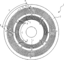
- FIG. 2 is a schematic plan view showing an example of a heater in which heat generating cells are arranged in a circular shape.
- FIG. 2 is a schematic plan view showing an example of a heater including two heat generating cell groups arranged in a circular shape.
- FIG. 3 is a schematic plan view showing a wiring example of a resistance heating line.
- FIG. 3 is a plan view for explaining a non-wiring area between adjacent heat generating cells.
- FIG. 7 is a schematic plan view showing another wiring example of the resistance heating wire.
- FIG. 7 is a schematic plan view showing another wiring example of the resistance heating wire.
- FIG. 7 is a schematic plan view showing a modification of the wiring of the resistance heating wire.
- FIG. 7 is a schematic plan view showing another modification of the wiring of the resistance heating wire.
- 7 is a graph showing an example of the temperature distribution of the heater immediately after power is turned on. It is a graph showing an example of temperature distribution when using a heater.
- FIG. 2 is a schematic perspective view showing an example of a fixing device using a heater.
- FIG. 3 is a schematic perspective view showing another example of a fixing device using a heater.
- 1 is a schematic diagram showing an example of an image forming apparatus using a heater.
- FIG. 3 is a plan view for explaining a non-wiring area between adjacent heat generating cells in a conventional heater.
- a plurality of heat generating cells (C) partitioned by virtual boundaries (B) are arranged side by side on a base body (2), and face the base body (2). It is a heater that heats an object to be heated.
- the heater (1) includes a base (2) and a resistance heating wire (3) formed in each heating cell (C) (see FIGS. 1 and 2).
- one or more pairs of power supply wiring (F) for supplying power to each heat generating cell (C), a power supply terminal for connecting to an external power supply, a temperature sensor, etc. can be provided on the base (2).
- the heat generating cell itself may be provided with power supply wiring.
- the heater (1) may heat the object by fixing its positional relationship with the object, or may move one or both of the heater and the object to relatively sweep the object to be heated. It can also heat things.
- the base (2) is a substrate that supports a plurality of heat generating cells (C).
- the surface shape of the base (2) is not particularly limited, and may be, for example, rectangular (see Figure 2), circular (see Figure 3), etc., but is not limited thereto, and may be square or L-shaped depending on the purpose. Any shape such as a shape, an arc shape, a fan shape, etc. can be selected. Further, the thickness of the base (2) may be determined depending on its material, planar dimensions, required strength, etc.
- the cross-sectional shape in the sweep direction is not only a planar shape but also a circular arc shape that is convex on the side facing the object to be heated and centered on an axis perpendicular to the sweep direction (i.e., a cylinder or cylinder parallel to the central axis). (a shape cut out on a flat plane).
- each resistance heating wiring can be arranged on the convex surface or on the opposite surface (concave surface).
- the material constituting the base (2) is not limited, and for example, metals, ceramics, composite materials thereof, etc. can be used.
- the metal constituting the base body (2) include steel, among which stainless steel is preferably used.
- the type of stainless steel is not particularly limited, and ferritic stainless steel and/or austenitic stainless steel are preferred. Among these stainless steels, varieties with particularly excellent heat resistance and/or oxidation resistance are preferred. Examples include SUS430, SUS436, SUS444, and SUS316L. These may be used alone or in combination of two or more.
- aluminum, magnesium, copper, and alloys of these metals can be used as metals constituting the base (2). These may be used alone or in combination of two or more.
- aluminum, magnesium, and alloys thereof have low specific gravity, so by employing these, it is possible to reduce the weight of the present heater. Further, since copper and its alloys have excellent thermal conductivity, by employing them, it is possible to improve the thermal uniformity of the present heater.
- the base (2) When using a conductive material such as metal as the material for the base (2), the base (2) is used for electrical insulation between the conductive material and the wiring provided thereon (resistance heating wire, power supply wiring, power supply terminal, etc.). ) is constructed by providing an insulating layer on a conductive material. In this case, the heat generating cell will be formed on the insulating layer.
- the material of the insulating layer is not particularly limited, but for example, glass, ceramics, glass-ceramics, etc. are preferable. Among these, when metal (such as stainless steel) is used as the material constituting the base (2), glass is preferable as the material for the insulating layer from the viewpoint of thermal expansion balance, and crystallized glass and semi-crystalline glass are preferable. More preferred.
- MO is an oxide of an alkaline earth metal (MgO, CaO, BaO, SrO, etc.).
- the thickness of the insulating layer is not particularly limited (for example, about 30 to 200 ⁇ m).
- the material of the base can achieve electrical insulation between the wiring provided thereon (resistance heating wire, power supply wiring, power supply terminal, etc.). It is fine as long as it is something.
- Preferred substrate materials include, for example, aluminum oxide, aluminum nitride, zirconia, silica, mullite, spinel, cordierite, silicon nitride, and the like. These may be used alone or in combination of two or more. Among these, aluminum oxide and aluminum nitride are more preferred.
- a composite material of metal and ceramics can also be used as the base (2).
- Preferred composite materials include, for example, SiC/C, SiC/Al, and the like. These may be used alone or in combination of two or more.
- heat generating cell A plurality of heat generating cells (C) partitioned by virtual boundaries (B) are arranged side by side on the base (2).
- the method of arranging the heat generating cells (C) is not limited, but an example of a basic configuration is an arrangement in which a plurality of heat generating cells (C) are lined up in one straight line or in the circumferential direction of one circle ( (See Figures 2 and 3).
- a plurality of heat generating cell groups having such a basic configuration may be arranged on one base (2) (see FIG. 4).
- Adjacent heat generating cells (C) are separated by a gap and are electrically insulated.
- the boundary line (B) is a boundary line designed to partition the plurality of heat generating cells (C) (see FIGS. 1 and 2).
- the boundary line (B) may be linear, curved, or wavy.
- the boundary line (B) can be set in a direction perpendicular to the arrangement direction of the plurality of heat generating cells (C) (for example, the one linear direction or the circumferential direction of the one circle). Further, the boundary line (B) may be set to be inclined with respect to the arrangement direction of the plurality of heat generating cells (C).
- the boundary line (B) may be perpendicular to the one straight line, or may be inclined at a predetermined angle with respect to the one straight line. may also be provided. Further, when the heat generating cell group is arranged in the circumferential direction of one circle, the boundary line (B) may be in the radial direction of the one circle, or may be inclined at a predetermined angle with respect to the circumferential direction. may be provided.
- the predetermined angle may be arbitrarily set according to the width of the heat generating cells (C) (size in the direction perpendicular to the direction in which the heat generating cells are arranged), etc., and for example, 15 degrees with respect to the direction in which the heat generating cells are arranged. ⁇ 90 degrees (or 90 degrees to 165 degrees), preferably 25 degrees to 65 degrees (or 115 degrees to 155 degrees), more preferably 35 degrees to 55 degrees (or 125 degrees to 145 degrees).
- the inclination of the boundary line (B) of each heat generating cell with respect to the arrangement direction of the heat generating cells does not have to be the same angle, but may be inclined at different angles. Good too.
- the boundary line (B) between C 1 and C 2 is inclined at 45 degrees with respect to the arrangement direction of the heat generating cells C 1 to C 4 .
- the boundary line (B) between C 2 and C 3 may be inclined at 135 degrees, and the boundary line (B) between C 3 and C 4 may be inclined at 45 degrees.
- the heater (1) is formed in each heat generating cell (C) near the boundary line (B) between a parallel wiring (L 1 ) in which a plurality of wirings are formed in parallel and an adjacent heat generating cell.
- the parallel wiring (L 1 ) is connected to a folded wiring (L 2 ) formed by folding back the parallel wiring (L 1 ), and is provided with one resistance heating line (3) having a zigzag shape as a whole (see FIG. 1).
- the zigzag shape means, for example, when three parallel wiring lines L 1 are arranged as L 11 , L 12 , and L 13 in this order, L 11 and L 12 are connected at one end by a folded wiring L 2 , and L 12 and L13 are connected at the other end by a folded wiring L2 . Further, when the four parallel wirings L 1 are sequentially L 11 , L 12 , L 13 , and L 14 , L 11 and L 12 are connected at one end of each, and L 12 and L 13 are connected at one end. Each other end is connected, and L13 and L14 are each connected at one end.
- the resistivity obtained from the material alone will be lower, so a zigzag shape that combines parallel wiring and folded wiring is used.
- the amount of heat required for a practical heater can be obtained by increasing the resistance value by making the wiring width thinner and increasing the wiring length by twice the number of turns.
- the thickness and width of the wiring are substantially the same within one heating cell (C).
- different heat generating cells (C) be made substantially the same.
- the film thickness and wiring width may be changed as necessary for the purpose of providing a temperature gradient as appropriate.
- the wiring width and the distance between wirings (insulation distance) can be set as appropriate (for example, both are 0.1 mm to 3.5 mm, preferably 0.3 mm to 2.0 mm, and more preferably 0.4 mm). ⁇ 1.2mm).
- the parallel wiring (L 1 ) is a wiring portion in which a plurality of resistance heating lines (3) are arranged substantially in parallel.
- the parallel wiring (L 1 ) is formed in a direction along the arrangement direction of the plurality of heat generating cells (C), that is, in a direction intersecting the boundary line (B).
- the parallel wiring (L 1 ) is a plurality of parallel wiring lines (L 1 ) formed in one resistance heating line in a direction substantially parallel to the one straight line. This is the wiring part.
- the parallel wiring (L 1 ) may be a wiring portion arranged so as to be approximately concentric.
- the shape of the parallel wiring (L 1 ) is not limited to a straight line or an arc shape, but can be a line with one or more bent parts, a meandering curve, or other irregularly shaped straight lines or curves. If a plurality of wirings are arranged substantially in parallel, it can be considered as parallel wiring (L 1 ).
- a plurality of heat generating cells (e.g. heat generating cells C1 and C2) are arranged in one row, and the parallel wiring L1 of each heat generating cell is connected to the parallel wiring L1 in the arrangement direction of the heat generating cells C. It is preferable that they overlap when extended. That is, if the parallel wiring L 1 of each heating cell C is a straight line, the parallel wiring L 1 will be in the same straight line, and if the parallel wiring L 1 is arcuate, the parallel wiring L 1 will be on the circumference of the same circle. preferable.
- the folded wiring (L 2 ) connects the ends of two adjacent parallel wirings (L 1 ) among the resistance heating wires (3), so that the two adjacent parallel wirings (L 1 ) This is a wiring portion that is connected to form one folded shape that is part of a zigzag fold.
- the number of parallel wires (L 1 ) included in one heat generating cell C is n
- the number of folded wires L 2 is usually n-1. If the heating cell is provided with holes or other components, the number is not limited to this.
- the angle between the parallel wiring (L 1 ) and the folded wiring (L 2 ) is not limited.
- the folded wiring (L 2 ) can be formed substantially parallel to the boundary line (B) between adjacent heat generating cells.
- the angle of inclination of the folded wiring (L 2 ) is not particularly limited, and may be, for example, an angle that is substantially parallel to the boundary line (B) (see FIG. 1). Furthermore, the plurality of folded wiring lines (L 2 ) included in the resistance heating line (3) of one heating cell (C) may have different inclination angles with respect to the parallel wiring line L 1 , but substantially It is preferable to have the same inclination angle.
- the resistance heating wires (3) between adjacent heat generating cells (C) are folded so as to reduce the blank area (non-heat generating part). It is preferable to deform the wiring (L 2 ) or change the inclination angle. For example, when the heat generating cells (C) are arranged side by side in one linear direction, the folded wiring (L 2 ) is approximately parallel to the one linear direction at the upper end or lower end in the boundary line (B) direction. can be formed.
- a conductive material that can generate heat according to the resistance value when energized can be used.
- this conductive material is not limited, for example, silver, copper, gold, platinum, palladium, rhodium, tungsten, molybdenum, rhenium (Re), ruthenium (Ru), etc. can be used. These may be used alone or in combination of two or more. When two or more types are used together, an alloy can be used. More specifically, silver-palladium alloy, silver-platinum alloy, platinum-rhodium alloy, silver-ruthenium, silver, copper, gold, etc. can be used.
- each heating cell (C) may have any resistance heating characteristic, it is preferable that a self-temperature balancing effect (self-temperature complementing effect) can be exerted between each heating cell.
- the conductive material constituting the resistance heating wire (3) has a positive temperature coefficient of resistance.
- the temperature coefficient of resistance in the temperature range of -200°C to 1000°C is preferably 100ppm/°C to 4400ppm/°C, and more preferably 300ppm/°C to 3700ppm/°C.
- it is particularly preferably 500 ppm/°C or more and 3000 ppm/°C or less.
- examples of such materials include silver-based alloys such as silver-palladium alloys.
- the heat generating cells surrounding the second heat generating cell behave so as to compensate for the temperature drop of the second heat generating cell.
- a heater including a plurality of resistance heating wires formed using a conductive material having a positive temperature coefficient of resistance is autonomously controlled to uniformly generate heat across a plurality of heating cells.
- the resistance heating wires (3) of the plurality of heating cells (C) connected to one pair of electrodes can be electrically connected in parallel.
- the heat generation cells connected in parallel can collectively control heat generation. It is preferable that the heat generating cells connected in parallel have substantially the same electrical characteristics such as resistance value and resistance heating characteristics.
- the extending portion (31) is a portion where one or both of the parallel wiring and the folded wiring of the resistance heating wire (3) constituting one heating cell exceeds the boundary line (B).
- the resistance heating wire (3) of the heating cell adjacent to the heating cell corresponds to the wiring pattern of the opposing extending portion, and has a portion (recessed portion) where the wiring is shortened or deformed so as to maintain electrical insulation.
- the resistance heating wires (3) are configured to include extending portions (31) alternately in the direction of the boundary line (B) (see FIG. 1). Thereby, it is possible to form a shape in which the periphery of the extension portion of one adjacent cell is surrounded by the wiring of the other adjacent cell. Note that, although the corresponding parallel wiring and folded wiring of each extending portion (31) of adjacent heat generating cells are usually arranged in parallel, the present invention is not limited thereto.
- a thermal blank area occurs between the extending part of one side and the retreating part of the other of adjacent heat generating cells, but since the extending part and the retreating part are arranged alternately in the direction of the boundary line, the thermal blank area is dispersed. be done.
- the wiring pattern and length of the extending portion (31) are not particularly limited. Further, the wiring pattern of the retracted portion of the adjacent heating cell (C) provided corresponding to the extending portion (31) is not limited, and the wiring pattern of the recessed portion of the adjacent heating cell (C) can be reduced to reduce the gap with the wiring of the extending portion of one heating cell, and to It may be determined as appropriate so that physical insulation is maintained.
- the extending portion (31) can be provided to be inclined at a predetermined angle with respect to the boundary line (B).
- the parallel wiring and/or the folded wiring corresponding to the extension part (31) can be bent or inclined with respect to each wiring other than the extension part.
- the extending portion (31) may be formed so as to sandwich the boundary line (B) and have all or a portion thereof inclined at a predetermined angle with respect to the boundary line (B). That is, the extending portion (31) may have a non-slanted portion.
- the extending portion may include an inclined portion and a non-slanted portion substantially parallel to the parallel wiring (L 1 ).
- the extending portion (31) By tilting the extending portion (31) with respect to the boundary line (B), the extending portion (31) is extended deeper beyond the boundary line (B), and the resistance heating wires of adjacent heat generating cells are connected at the boundary portion. It can be an intertwined pattern. This makes it possible to reduce blank areas for heat generation and to significantly suppress temperature drop at the boundary areas.
- the inclination angle of the extending portion (31) with respect to the boundary line (B) can be selected as appropriate (for example, 40 degrees to 140 degrees, preferably 60 degrees to 120 degrees, more preferably 80 degrees to 100 degrees).
- the resistance heating wire (3) has a curved portion (33) in the parallel wiring (L 1 ), and the curved portion (33) is connected to the resistance heating wire (3) of the adjacent heating cell (C). ) can be formed in a convex shape toward the gap (see FIG. 1).
- the curved portion (33) heat generation is increased in a portion where the wiring density of the resistance heating wire is lower than other portions (for example, the gap between the extending portion of one heating cell and the receding portion of the adjacent heating cell). be able to.
- the length of the curved portion (the length of the line segment connecting both ends of the curved portion) and the length of the convex protrusion are not particularly limited, and may be appropriately selected so as to fill the gap between the resistance heating wires.
- FIG. 1 and 2 show a heater 1 in which a plurality of heat generating cells C partitioned by boundary lines B are arranged on a rectangular base 2 in one straight line direction (long side direction of the base 2).
- a boundary line B between adjacent heat generating cells C is inclined at a constant angle with respect to the one straight line.
- Inside each heat generating cell C there is a parallel wiring line L1 in which a plurality of wiring lines are formed in parallel, and a folded line formed to fold back the parallel wiring line L1 in the vicinity of the boundary line B between the adjacent heat generating cell C.
- the wiring L2 is connected to form one resistance heating wire 3 which has a meandering shape as a whole.
- the folded wiring L2 is formed substantially parallel to the boundary line B.
- the resistance heating line 3 of one heat generating cell C has an extending portion 31 formed to extend the parallel wiring L 1 beyond the boundary line B, and The wiring of the resistance heating wire 3 has a retracted portion 32 that is shortened to correspond to the extended portion 31 .
- the resistance heating wires 3 of adjacent heating cells are provided with extending portions 31 alternately in the direction of the boundary line B. Further, the extending portion 31 is provided so as to sandwich the boundary line B, and the entire extension portion 31 is inclined at a constant angle with respect to the boundary line B. Further, the resistance heating wire 3 has a curved portion 33 in the parallel wiring L1 , and the curved portion 33 is formed in a convex shape toward the gap between the resistance heating wires 3 of adjacent heating cells C.
- the resistance heating wires 3 of each heating cell C are electrically connected in parallel by a pair of power supply wirings F.
- the width of the base 2 is narrow, and it is suitable for use in heating an object by relatively sweeping the base 2 and the object to be heated in the short side direction of the base 2. Since the extending portions 31 are arranged alternately in the direction of the boundary line B, thermal blank portions where the resistance heating wire 3 does not exist are distributed between adjacent heating cells.
- FIG. 3 shows a heater 1 in which a plurality of heat generating cells C partitioned by boundary lines B are arranged side by side in the circumferential direction of one circle on a circular base body 2.
- the boundary line B between adjacent heat generating cells C is inclined at a constant angle with respect to the line segment dividing the one circle equiangularly around the center.
- the resistance heating wire 3 of each heating cell C is arranged so that the parallel wiring L 1 is folded back near the boundary line B between the plurality of parallel wirings L 1 arranged concentrically in parallel and the adjacent heating cell C.
- the formed folded wiring L2 is connected to form a meandering shape as a whole.
- the heater of this example has the same configuration as that shown in the previous figure.
- FIG. 4 shows an example in which two groups of heat-generating cells C arranged in the circumferential direction are provided on a circular base 2.
- FIG. 5 shows a heater 1 in which a plurality of heat generating cells C defined by boundary lines B are arranged on a rectangular base 2 in the long side direction of the base 2.
- a boundary line B between adjacent heat generating cells C is set in a direction perpendicular to the arrangement direction of the plurality of heat generating cells C.
- the other configurations are similar to the heater shown in FIG. 1.
- FIG. 6 is a diagram for explaining the non-wiring portion I of the resistance heating line 3 that occurs between adjacent heating cells C.
- the wiring pattern of the resistance heating wire 3 of this heater allows the non-wiring portions I to be dispersed in the direction in which the heating cells C are arranged.
- FIG. 7 and 8 show wiring examples in which the number of parallel wiring lines L1 constituting the resistance heating line 3 is four and eight. As shown in FIG. 7, even if the resistance heating wires 3 of adjacent heating cells C cannot have extending portions 31 alternately in the direction of boundary line B, non-wiring portions between adjacent heating cells C may A similar effect can be obtained by deforming the wiring so as to reduce it as much as possible and to disperse the non-wiring portions in the direction in which the heating cells C are arranged.
- each folded wiring L2 can have an arbitrary inclination angle with respect to the boundary line B.
- the extending portion 31 sandwiches the boundary line B, a part of which is inclined at a certain angle with respect to the boundary line B, and the other part is arranged in the arrangement of the heat generating cells C.
- the direction can be parallel to the direction.
- the folded wiring L2 may be provided in a direction parallel to the arrangement direction of the heat generating cells C, or may be folded in a hairpin shape.
- FIGS. 11 and 12 show temperature profiles measured using a heater in which seven heat generating cells C1 to C7 are arranged in the straight X direction.
- Figure 11 shows the temperature profile immediately after applying voltage to the heater (approximately 12 seconds later). It can be seen that the heater operating temperature is quickly reached after the power is turned on.
- FIG. 12 shows a temperature profile when the temperature of the heater reaches the standard after applying a voltage to the heater, and high uniformity of heat is obtained throughout the heater.
- the heater (1) can be incorporated into an image forming device such as a printing machine, a copying machine, or a facsimile machine, a fixing device, etc., and can be used as a fixing heater for fixing toner, ink, etc. onto a recording medium. Moreover, it can be incorporated into a heating machine and used as a heating device for uniformly heating (drying, baking, etc.) a target object such as a panel. In addition, heat treatment of metal products, coating films formed on substrates of various shapes, heat treatment of films, etc. can be suitably performed.
- the fixing device including the present heater can have a configuration appropriately selected depending on the material and shape of the object to be heated, the fixing means, and the like. For example, when fixing toner or the like on a recording medium such as paper by providing a fixing unit that involves pressure bonding, or when bonding multiple members together, a fixing unit that includes a heating unit that includes a heater and a pressure unit is used. It can be a device. Of course, it is also possible to use a fixing means that does not involve pressure bonding.
- the fixing device 5 is preferably used to fix an unfixed image containing toner formed on the surface of a recording medium such as paper or film to the recording medium.
- the fixing device 5 includes a rotatable fixing roll 51 and a rotatable pressure roll 54 , and the heater 1 is disposed inside the fixing roll 51 .
- the heater 1 is preferably disposed close to the inner surface of the fixing roll 51.
- the heater 1 is fixed inside a heater holder 53 made of a material capable of conducting heat generated by the heater 1, like the fixing means 5 shown in the figure, and the heat generated by the heater 1 is transferred to the fixing roll 51. It is also possible to have a structure in which the information is transmitted from the inside to the outside surface.
- FIG. 14 also shows the main parts of the fixing device 5 disposed in an electrophotographic image forming apparatus.
- the fixing device 5 includes a rotatable fixing roll 51 and a rotatable pressure roll 54.
- a pad 52 is disposed inside the fixing roll 51.
- the heater 1 is arranged along the cylindrical surface of the fixing roll 51.
- a voltage is applied from a power supply device (not shown) to cause the heater 1 to generate heat, and the heat is transmitted to the fixing roll 51. Then, when a recording medium having an unfixed toner image on its surface is supplied between the fixing roll 51 and the pressure roll 54, the toner is released at the pressure contact portion of the fixing roll 51 and the pressure roll 54. It melts to form a fixed image. Since it has a pressure contact portion of the fixing roll 51 and the pressure roll 54, they rotate together. As described above, the heater 1 suppresses the local temperature rise that tends to occur when a small recording medium is used, so temperature unevenness in the fixing roll 51 is less likely to occur, and fixing can be performed uniformly. Can be done. Further, even immediately after the start of use of the fixing device, since the adjacent portions of the heat generating cells of the heater 1 are excellent in uniformity, substantially the same fixing results as during continuous use can be obtained.
- the fixing device including the present heater 1 may be a mold including an upper mold and a lower mold, and a heater may be disposed inside at least one of the upper mold and the lower mold.
- the fixing device equipped with this heater 1 can be installed in image forming devices such as electrophotographic printing machines and copying machines, as well as household electrical appliances, precision instruments for business use, and experiments, etc., for heating, heat retention, etc. suitable as a heat source.
- the image forming apparatus including the present heater can have a configuration appropriately selected depending on the object to be heated, the purpose of heating, and the like.
- the present invention includes an image forming means for forming an unfixed image on the surface of a recording medium such as paper or film, and a fixing means 5 for fixing the unfixed image on the recording medium.
- the fixing means 5 is the image forming apparatus 4 equipped with the present heater 1 .
- the image forming apparatus 4 can be configured to include a recording medium conveying means and a control means for controlling each means.
- FIG. 15 is a schematic diagram showing the main parts of the electrophotographic image forming apparatus 4.
- the image forming means may be either a system that includes a transfer drum or a system that does not include a transfer drum, but FIG. 15 shows an embodiment that includes a transfer drum.
- the image forming means while rotating, the charged surface of the photosensitive drum 44, which has been charged to a predetermined potential by the charging device 43, is irradiated with the laser output from the laser scanner 41, and the toner supplied from the developing device 45 is irradiated with the charged surface of the photosensitive drum 44. An electrostatic latent image is formed. Next, the toner image is transferred onto the surface of a transfer drum 46 that is interlocked with the photosensitive drum 44 using the potential difference.
- a toner is a particle containing a binder resin, a colorant, and an additive, and the melting temperature of the binder resin is usually 90°C to 250°C.
- the surfaces of the photosensitive drum 44 and the transfer drum 46 may be provided with a cleaning device for removing insoluble toner and the like.
- the fixing unit 5 can have the same configuration as the fixing device 5 described above, and includes therein a pressure roll 54 and a heater holder 53 holding a paper-feeding direction current-carrying type heater 1, and is interlocked with the pressure roll 54.
- a fixing roll 51 is provided.
- a recording medium having an unfixed image from the image forming means is supplied between the fixing roll 51 and the pressure roll 54.
- the heat of the fixing roll 51 melts the toner image on the recording medium, and the melted toner is further pressed at the pressure contact portion between the fixing roll 51 and the pressure roll 54, so that the toner image is transferred to the recording medium. will be established.
- a fixing belt with the heater 1 disposed close thereto may be provided.
- the temperature of the fixing roll 51 is uneven and the amount of heat given to the toner is too small, the toner will peel off from the recording medium, while if the amount of heat is too large, the toner will stick to the fixing roll 51.
- the toner may adhere to the recording medium, and the fixing roll 51 may rotate once and re-adhere to the recording medium.
- the fixing means 5 including the heater of the present invention the temperature can be quickly adjusted to a predetermined temperature, so that problems can be suppressed.
- the heat blank in the adjacent portions of the heat generating cells of the heater 1 is dispersed, resulting in excellent uniformity, so even if the recording medium passes (sweeps), it will not overheat or overheat. This eliminates the problem of insufficient areas and provides almost the same fixing results as when used continuously.
- the image forming apparatus of the present invention suppresses excessive temperature rise in non-sheet passing areas during use, and is suitable for electrophotographic printing machines, copying machines, and the like.
- the heating device including the present heater can have a configuration appropriately selected depending on the size, shape, etc. of the object to be heated.
- the present invention includes, for example, a casing, a sealable window disposed for taking in and taking out objects to be heat-treated, and a movable heater disposed inside the casing. Can be configured.
- the inside of the casing includes a heat-treated object installation section for placing the heat-treated objects, an exhaust section for discharging gas when the heat-treated objects are heated, and a heat-treated object installation section for disposing the heat-treated objects, an exhaust section for discharging gas when the heat-treated objects are heated, and a A pressure adjustment unit such as a vacuum pump or the like can be provided to adjust the internal pressure.
- heating may be performed with the object to be heat treated and the heater section fixed, or may be performed while moving either one of them.
- This heating device is suitable as a device for drying a heat-treated material containing water, an organic solvent, etc. at a desired temperature. It can be used as a vacuum dryer (reduced pressure dryer), a pressure dryer, a dehumidifying dryer, a hot air dryer, an explosion-proof dryer, and the like. Further, it is suitable as an apparatus for firing unfired products such as LCD panels and organic EL panels at a desired temperature. And, it can be used as a reduced pressure firing machine, a pressure firing machine, etc.
Landscapes
- Physics & Mathematics (AREA)
- General Physics & Mathematics (AREA)
- Resistance Heating (AREA)
- Surface Heating Bodies (AREA)
- Fixing For Electrophotography (AREA)
- Control Of Resistance Heating (AREA)
Priority Applications (3)
| Application Number | Priority Date | Filing Date | Title |
|---|---|---|---|
| US18/874,348 US20250377617A1 (en) | 2022-07-22 | 2023-06-23 | Heater, fixing device, image formation device, and heating device |
| CN202380040163.XA CN119213866A (zh) | 2022-07-22 | 2023-06-23 | 加热器、定影装置、图像形成装置以及加热装置 |
| KR1020247038113A KR20250044180A (ko) | 2022-07-22 | 2023-06-23 | 히터, 정착 장치, 화상 형성 장치 및 가열 장치 |
Applications Claiming Priority (2)
| Application Number | Priority Date | Filing Date | Title |
|---|---|---|---|
| JP2022117504A JP7554490B2 (ja) | 2022-07-22 | 2022-07-22 | ヒータ、定着装置、画像形成装置及び加熱装置 |
| JP2022-117504 | 2022-07-22 |
Publications (1)
| Publication Number | Publication Date |
|---|---|
| WO2024018826A1 true WO2024018826A1 (ja) | 2024-01-25 |
Family
ID=89617631
Family Applications (1)
| Application Number | Title | Priority Date | Filing Date |
|---|---|---|---|
| PCT/JP2023/023329 Ceased WO2024018826A1 (ja) | 2022-07-22 | 2023-06-23 | ヒータ、定着装置、画像形成装置及び加熱装置 |
Country Status (6)
| Country | Link |
|---|---|
| US (1) | US20250377617A1 (https=) |
| JP (1) | JP7554490B2 (https=) |
| KR (1) | KR20250044180A (https=) |
| CN (1) | CN119213866A (https=) |
| TW (1) | TWI864881B (https=) |
| WO (1) | WO2024018826A1 (https=) |
Families Citing this family (1)
| Publication number | Priority date | Publication date | Assignee | Title |
|---|---|---|---|---|
| CN121369807B (zh) * | 2025-12-24 | 2026-04-24 | 重庆明月湖智能科技发展有限公司 | 一种智能电加热手套 |
Citations (3)
| Publication number | Priority date | Publication date | Assignee | Title |
|---|---|---|---|---|
| JP2002141159A (ja) * | 2000-11-02 | 2002-05-17 | Ibiden Co Ltd | セラミックヒータ |
| WO2017090692A1 (ja) * | 2015-11-27 | 2017-06-01 | 株式会社美鈴工業 | ヒータ、定着装置、画像形成装置及び加熱装置 |
| WO2019112058A1 (ja) * | 2017-12-08 | 2019-06-13 | 株式会社美鈴工業 | ヒータ、定着装置、画像形成装置及び加熱装置 |
Family Cites Families (6)
| Publication number | Priority date | Publication date | Assignee | Title |
|---|---|---|---|---|
| JPH10142991A (ja) * | 1996-11-11 | 1998-05-29 | Bando Chem Ind Ltd | 定着用加熱ローラ |
| JPWO2003102699A1 (ja) | 2002-06-03 | 2005-09-29 | 富士ゼロックス株式会社 | ヒートローラ |
| TWI281833B (en) * | 2004-10-28 | 2007-05-21 | Kyocera Corp | Heater, wafer heating apparatus and method for manufacturing heater |
| JP5441655B2 (ja) | 2009-12-10 | 2014-03-12 | 株式会社クラベ | ステアリングホイール用ヒータ装置 |
| JP6228458B2 (ja) | 2011-11-15 | 2017-11-08 | 株式会社美鈴工業 | ヒータ並びにそれを備える定着装置及び乾燥装置 |
| JP6424010B2 (ja) * | 2014-03-31 | 2018-11-14 | 株式会社美鈴工業 | ヒータとそれを備える定着装置、画像形成装置及び加熱装置、並びにヒータの製造方法 |
-
2022
- 2022-07-22 JP JP2022117504A patent/JP7554490B2/ja active Active
-
2023
- 2023-06-23 KR KR1020247038113A patent/KR20250044180A/ko active Pending
- 2023-06-23 WO PCT/JP2023/023329 patent/WO2024018826A1/ja not_active Ceased
- 2023-06-23 US US18/874,348 patent/US20250377617A1/en active Pending
- 2023-06-23 CN CN202380040163.XA patent/CN119213866A/zh active Pending
- 2023-07-13 TW TW112126208A patent/TWI864881B/zh active
Patent Citations (3)
| Publication number | Priority date | Publication date | Assignee | Title |
|---|---|---|---|---|
| JP2002141159A (ja) * | 2000-11-02 | 2002-05-17 | Ibiden Co Ltd | セラミックヒータ |
| WO2017090692A1 (ja) * | 2015-11-27 | 2017-06-01 | 株式会社美鈴工業 | ヒータ、定着装置、画像形成装置及び加熱装置 |
| WO2019112058A1 (ja) * | 2017-12-08 | 2019-06-13 | 株式会社美鈴工業 | ヒータ、定着装置、画像形成装置及び加熱装置 |
Also Published As
| Publication number | Publication date |
|---|---|
| CN119213866A (zh) | 2024-12-27 |
| US20250377617A1 (en) | 2025-12-11 |
| JP7554490B2 (ja) | 2024-09-20 |
| JP2024014572A (ja) | 2024-02-01 |
| TW202423171A (zh) | 2024-06-01 |
| TWI864881B (zh) | 2024-12-01 |
| KR20250044180A (ko) | 2025-03-31 |
Similar Documents
| Publication | Publication Date | Title |
|---|---|---|
| JP6424010B2 (ja) | ヒータとそれを備える定着装置、画像形成装置及び加熱装置、並びにヒータの製造方法 | |
| KR100572290B1 (ko) | 적어도 하나의 사이클 경로 저항기를 갖는 히터와 이를사용하는 화상 가열 장치 | |
| JP2012252127A (ja) | 加熱体及び画像加熱装置 | |
| CN107615879B (zh) | 加热器、具备该加热器的定影装置、图像形成装置和加热装置 | |
| JP6161859B1 (ja) | ヒータ、定着装置、画像形成装置及び加熱装置 | |
| WO2014034744A1 (ja) | ヒータ並びにそれを備える定着装置、画像形成装置及び加熱装置 | |
| KR102873660B1 (ko) | 히터, 정착 장치, 화상 형성 장치 및 가열 장치 | |
| WO2024018826A1 (ja) | ヒータ、定着装置、画像形成装置及び加熱装置 | |
| CN205644025U (zh) | 加热器以及图像形成装置 | |
| JP2009059539A (ja) | 板状ヒータ、加熱装置、画像形成装置 | |
| JP5320549B2 (ja) | セラミックヒータ、加熱装置、画像形成装置 | |
| JP2009087548A (ja) | セラミックヒータ、加熱装置、画像形成装置 | |
| US20240260139A1 (en) | Heater, fixing device, image-forming device, and heating device | |
| JPH06332332A (ja) | 加熱定着装置 | |
| JP2014089330A (ja) | 画像形成装置 | |
| JP2009009017A (ja) | 板状ヒータ、加熱装置、画像形成装置 | |
| JP2001217061A (ja) | ヒータ、定着装置および画像形成装置 |
Legal Events
| Date | Code | Title | Description |
|---|---|---|---|
| 121 | Ep: the epo has been informed by wipo that ep was designated in this application |
Ref document number: 23842757 Country of ref document: EP Kind code of ref document: A1 |
|
| WWE | Wipo information: entry into national phase |
Ref document number: 202380040163.X Country of ref document: CN |
|
| WWE | Wipo information: entry into national phase |
Ref document number: 18874348 Country of ref document: US |
|
| WWE | Wipo information: entry into national phase |
Ref document number: 2401008340 Country of ref document: TH |
|
| WWP | Wipo information: published in national office |
Ref document number: 202380040163.X Country of ref document: CN |
|
| NENP | Non-entry into the national phase |
Ref country code: DE |
|
| WWP | Wipo information: published in national office |
Ref document number: 1020247038113 Country of ref document: KR |
|
| 122 | Ep: pct application non-entry in european phase |
Ref document number: 23842757 Country of ref document: EP Kind code of ref document: A1 |
|
| WWP | Wipo information: published in national office |
Ref document number: 18874348 Country of ref document: US |