WO2024005174A1 - 導電性炭素フィラーを含む試薬層、当該試薬層を有するセンサ、および当該試薬層の形成方法 - Google Patents
導電性炭素フィラーを含む試薬層、当該試薬層を有するセンサ、および当該試薬層の形成方法 Download PDFInfo
- Publication number
- WO2024005174A1 WO2024005174A1 PCT/JP2023/024307 JP2023024307W WO2024005174A1 WO 2024005174 A1 WO2024005174 A1 WO 2024005174A1 JP 2023024307 W JP2023024307 W JP 2023024307W WO 2024005174 A1 WO2024005174 A1 WO 2024005174A1
- Authority
- WO
- WIPO (PCT)
- Prior art keywords
- reagent layer
- reagent
- group
- electrode
- polymer
- Prior art date
- Legal status (The legal status is an assumption and is not a legal conclusion. Google has not performed a legal analysis and makes no representation as to the accuracy of the status listed.)
- Ceased
Links
Images


Classifications
-
- A—HUMAN NECESSITIES
- A61—MEDICAL OR VETERINARY SCIENCE; HYGIENE
- A61B—DIAGNOSIS; SURGERY; IDENTIFICATION
- A61B5/00—Measuring for diagnostic purposes; Identification of persons
- A61B5/145—Measuring characteristics of blood in vivo, e.g. gas concentration or pH-value ; Measuring characteristics of body fluids or tissues, e.g. interstitial fluid or cerebral tissue
- A61B5/1468—Measuring characteristics of blood in vivo, e.g. gas concentration or pH-value ; Measuring characteristics of body fluids or tissues, e.g. interstitial fluid or cerebral tissue using chemical or electrochemical methods, e.g. by polarographic means
- A61B5/1486—Measuring characteristics of blood in vivo, e.g. gas concentration or pH-value ; Measuring characteristics of body fluids or tissues, e.g. interstitial fluid or cerebral tissue using chemical or electrochemical methods, e.g. by polarographic means using enzyme electrodes, e.g. with immobilised oxidase
- A61B5/14865—Measuring characteristics of blood in vivo, e.g. gas concentration or pH-value ; Measuring characteristics of body fluids or tissues, e.g. interstitial fluid or cerebral tissue using chemical or electrochemical methods, e.g. by polarographic means using enzyme electrodes, e.g. with immobilised oxidase invasive, e.g. introduced into the body by a catheter or needle or using implanted sensors
-
- A—HUMAN NECESSITIES
- A61—MEDICAL OR VETERINARY SCIENCE; HYGIENE
- A61B—DIAGNOSIS; SURGERY; IDENTIFICATION
- A61B5/00—Measuring for diagnostic purposes; Identification of persons
- A61B5/145—Measuring characteristics of blood in vivo, e.g. gas concentration or pH-value ; Measuring characteristics of body fluids or tissues, e.g. interstitial fluid or cerebral tissue
- A61B5/14532—Measuring characteristics of blood in vivo, e.g. gas concentration or pH-value ; Measuring characteristics of body fluids or tissues, e.g. interstitial fluid or cerebral tissue for measuring glucose, e.g. by tissue impedance measurement
-
- G—PHYSICS
- G01—MEASURING; TESTING
- G01N—INVESTIGATING OR ANALYSING MATERIALS BY DETERMINING THEIR CHEMICAL OR PHYSICAL PROPERTIES
- G01N27/00—Investigating or analysing materials by the use of electric, electrochemical, or magnetic means
- G01N27/26—Investigating or analysing materials by the use of electric, electrochemical, or magnetic means by investigating electrochemical variables; by using electrolysis or electrophoresis
- G01N27/28—Electrolytic cell components
- G01N27/30—Electrodes, e.g. test electrodes; Half-cells
- G01N27/327—Biochemical electrodes, e.g. electrical or mechanical details for in vitro measurements
- G01N27/3271—Amperometric enzyme electrodes for analytes in body fluids, e.g. glucose in blood
- G01N27/3272—Test elements therefor, i.e. disposable laminated substrates with electrodes, reagent and channels
-
- A—HUMAN NECESSITIES
- A61—MEDICAL OR VETERINARY SCIENCE; HYGIENE
- A61B—DIAGNOSIS; SURGERY; IDENTIFICATION
- A61B2562/00—Details of sensors; Constructional details of sensor housings or probes; Accessories for sensors
- A61B2562/02—Details of sensors specially adapted for in-vivo measurements
-
- A—HUMAN NECESSITIES
- A61—MEDICAL OR VETERINARY SCIENCE; HYGIENE
- A61B—DIAGNOSIS; SURGERY; IDENTIFICATION
- A61B2562/00—Details of sensors; Constructional details of sensor housings or probes; Accessories for sensors
- A61B2562/12—Manufacturing methods specially adapted for producing sensors for in-vivo measurements
- A61B2562/125—Manufacturing methods specially adapted for producing sensors for in-vivo measurements characterised by the manufacture of electrodes
Definitions
- the present invention relates to a reagent layer and a sensor containing a conductive carbon filler. More specifically, the present invention provides a conductive carbon filler dispersant as an agent for improving the dispersibility of conductive carbon filler in an aqueous solvent, a reagent layer containing the dispersant, the conductive carbon filler, and a cationic mediator. , a sensor including the reagent layer, and a method for forming the reagent layer.
- sensors have been known that measure analytes in a sample by making proteins act on them.
- Such sensors include electrochemical sensors that use enzymes, such as glucose oxidoreductase, and, if necessary, redox mediators (redox substances that mediate electron transfer) or redox polymers (redox polymers (redox substances via linkers, etc.).
- enzymes such as glucose oxidoreductase
- redox mediators redox substances that mediate electron transfer
- redox polymers redox polymers (redox substances via linkers, etc.
- An example of this is a glucose sensor fabricated using a polymer bonded with a mediator.
- Glucose sensors are used, for example, for self-testing of blood sugar levels, and in the past, it was common to collect a small amount of blood to use as a sample, but in recent years, glucose sensors have been implanted into living organisms to measure the amount of blood in the blood.
- implantable electrochemical glucose sensors have also been developed that continuously measure glucose in the interstitium.
- Glucose sensors are also used to measure glucose in samples other than biological materials, such as culture media.
- Such a glucose sensor measures the glucose concentration in a sample continuously or semi-continuously for a long period of time, typically from several days to several weeks.
- Patent Document 1 discloses a sensor made of a carbon black dispersion using hydroxypropylcellulose
- Patent Document 2 discloses an enzyme-immobilized electrode using ethyl cellulose as a binder and carbon particles. is disclosed.
- a reagent layer containing a conductive carbon filler and a redox mediator or redox polymer, and further containing an oxidoreductase, etc. as necessary, on a working electrode (enzyme electrode), etc. it is necessary to A reagent solution in which these necessary components are dispersed is prepared, and the reagent solution is applied to a desired area and dried.
- conductive carbon fillers generally have strong hydrophobicity and therefore are difficult to disperse in aqueous solvents, and also tend to aggregate due to van der Waals forces, making it difficult to maintain a dispersed state.
- the detection sensitivity of the analyte may be significantly reduced, and the detection sensitivity may be significantly reduced, or it may be difficult to detect the analyte for a long period of time in a humid environment such as in vivo or in a culture medium. In long-term measurements (continuous monitoring), problems such as poor durability occur. Note that it is appropriate to dissolve the oxidoreductase in an aqueous solvent, and it is not appropriate to use an organic solvent as a solvent for preparing the reagent solution.
- One aspect of the present invention is to provide a reagent layer and a method for forming the same for producing an electrochemical sensor that can detect an analyte with high sensitivity.
- the present inventors have discovered that in a reagent solution prepared preferably under specific conditions using a conductive carbon filler, a cationic redox mediator or a redox polymer (cationic mediator), and an anionic dispersant, conductive
- the carbon particles do not aggregate or precipitate, resulting in a good dispersion state, and the reagent layer formed using such a reagent solution can closely adsorb the cationic mediator onto the electrode.
- an electrochemical sensor has improved analyte detection sensitivity and excellent durability for continuous monitoring, leading to the completion of the present invention.
- the present invention includes at least the following matters.
- the anionic dispersant (b) is a polymer having a carboxy group and/or a sulfo group in its side chain.
- the reagent layer according to Item 3 wherein the anionic dispersant (b) is a polymer containing at least one selected from the group consisting of acrylic acid-derived units, maleic acid-derived units, and styrene sulfonic acid-derived units.
- the anionic dispersant (b) is a polymer containing at least one selected from the group consisting of acrylic acid-derived units, maleic acid-derived units, and styrene sulfonic acid-derived units.
- the cationic mediator (c) is a compound in which the redox mediator compound (c1) and the cationic polymer (c2) are bonded, optionally via a linker part (c3). reagent layer.
- the cationic polymer (c2) has a quaternary ammonium cation group.
- the anionic dispersant (b) is a polymer containing at least one selected from the group consisting of acrylic acid-derived units, maleic acid-derived units, and sty
- the reagent layer according to Item 1 wherein the conductive carbon filler (a) is carbon black.
- Item 2 The reagent layer according to Item 1, further comprising an oxidoreductase (e) that oxidizes or reduces the analyte.
- oxidoreductase (e) is of a coenzyme-binding type.
- Si2 The reagent layer according to Item 8, wherein the oxidoreductase (e) is crosslinked with the cationic polymer (c2).
- FIG. 11 An electrochemical sensor for detecting or quantifying an analyte, comprising a working electrode, a counter electrode, and a reagent layer according to any one of Items 1 to 10.
- FIG. 12 The electrochemical sensor according to Item 11, further comprising a reference electrode.
- FIG. 13 The electrochemical sensor according to item 11, further comprising a protective film covering at least the reagent layer.
- [Section 14] (1) A step of preparing a reagent solution containing a conductive carbon filler (a), an anionic dispersant (b), and a cationic mediator (c), (2) a step of applying the reagent solution to a reagent layer forming site; and (3) a step of drying the applied reagent solution to form a reagent layer.
- a method for forming a reagent layer comprising: [Section 15] Item 15. The method for forming a reagent layer according to Item 14, wherein the pH of the reagent solution is 8.0 or less. [Section 16] Item 16.
- Item 17 The method for forming a reagent layer according to Item 16, wherein the metal ion in the reagent solution is an alkali metal ion, and the concentration thereof is less than 100 mM.
- the anionic dispersant (b) is a polymer having a weight average molecular weight of 70,000 or less and containing at least one selected from the group consisting of acrylic acid-derived units, maleic acid-derived units, and styrene sulfonic acid-derived units. 15. The method for forming a reagent layer according to 14.
- the cationic mediator (c) is formed by bonding a redox mediator compound (c1) and a cationic polymer (c2) having a quaternary ammonium cation group, optionally via a linker part (c3).
- Item 15 The method for forming a reagent layer according to Item 14, wherein the reagent layer is a compound that is
- a conductive carbon filler can be favorably dispersed in a reagent solution containing an aqueous solvent.
- a reagent liquid carbon dispersion liquid
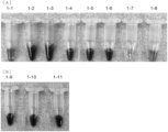
- the conductive carbon material is "dispersed” (including “redispersion") or "agglomerated” (including “agglomeration/precipitation”) in the reagent solution depends mostly on can be visually determined. For example, if the conductive carbon material is "agglomerated”, floating or precipitated aggregates can be easily visually confirmed.
- Centrifugal separation treatment can also be used when determining dispersion and aggregation of the conductive carbon filler. For example, if a reagent solution in which conductive carbon filler is "dispersed” is centrifuged, the conductive carbon filler will not precipitate, but if a reagent solution in which conductive carbon filler is "agglomerated” is centrifuged, If separated, the agglomerates settle out and separate into a layer of conductive carbon filler and a clear aqueous phase.
- the processing conditions for centrifugation can be, for example, 10,000 x g for 5 minutes, but may be adjusted as appropriate depending on the embodiment, taking into account, for example, the type of conductive carbon filler and its concentration. can.
- FIG. 1 is a plan view of a sensor in one embodiment of the invention.
- FIG. 1(A) shows the entire sensor
- FIG. 1(B) shows an enlarged view of the tip portion of the sensor.
- FIG. 2 is a cross-sectional view of the sensor at a specific portion of FIG. 1(B).
- FIG. 2(A) is a sectional view taken along the line AA in FIG. 1(B).
- FIG. 2(B) is a sectional view taken along the BB arrow in FIG. 1(B).
- FIG. 2(C) is a sectional view taken along the line CC in FIG. 1(B).
- FIG. 3 is a top view showing another example of the front side (the side having the working electrode and the reference electrode) of the sensor in one embodiment of the present invention.
- FIG. 3 is a top view showing another example of the front side (the side having the working electrode and the reference electrode) of the sensor in one embodiment of the present invention.
- FIG. 3 is a top view showing another
- FIG. 4 is a sectional view taken along the line A-A' in FIG. 3.
- FIG. 5 is a sectional view taken along the line B-B' in FIG. 4.
- FIG. 6 is a sectional view taken along the line C-C' in FIG. 4.
- FIG. 7 is a plan view of a sensor in one embodiment of the invention.
- FIG. 7(A) shows the electrode pattern before the film (insulating resist film) is formed
- FIG. 7(B) shows the electrode pattern after the film is formed.
- FIG. 8 is an image of recovered liquid samples derived from various reagent liquid samples prepared in Test Example 1 and reflecting the dispersion effect of carbon black. [A] Recovery liquid samples corresponding to reagent liquid samples 1-1 to 1-8, respectively.
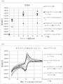
- FIG. 9 shows the measurement results regarding the responsiveness of the sensor in Test Example 6.
- FIG. 10 shows the measurement results regarding the durability of the sensor in Test Example 7.
- the reagent layer of the present invention includes a conductive carbon filler (a), an anionic dispersant (b), and a cationic mediator (c).
- the reagent layer of the present invention is a layer that can be formed by a formation method using a carbon dispersion liquid as described below, that is, a reagent liquid in which conductive carbon filler (a) is dispersed, and is preferably a layer that can be formed by a formation method using a carbon dispersion liquid as described later.
- This layer includes a carbon filler (a), an anionic dispersant (b), and a cationic mediator (c) in a uniform state.
- Conductive carbon filler in the present invention is not limited to a specific type, but takes into account the embodiments of the present invention (reagent layer, electrochemical sensor applications, etc.), effects, etc.
- Various conductive carbon fillers can be used.
- conductive carbon filler conductive carbon materials having various shapes such as spherical (particulate), scale-like, fibrous, and porous shapes can be used.
- the conductive carbon filler (a) may be used alone or in combination of two or more types (for example, may be used in combination).
- Examples of the conductive carbon filler include carbon black, graphite powder, porous carbon materials, nanocarbon materials, and the like.
- Specific examples of carbon black include furnace black, thermal black, acetylene black, Ketjen black, and channel black.
- Specific examples of graphite powder include pyrolytic graphite and spherical graphite.
- Specific examples of porous carbon materials include not only activated carbon powder or activated carbon fibers having mesopores of 2 to 50 nm, but also carbon materials having continuous pores in which mesopores are connected.
- Specific examples of nanocarbon materials include single-walled carbon nanotubes, multi-walled carbon nanotubes, graphene, fullerenes, carbon nanohorns, and carbon nanocoils.
- the size of the conductive carbon filler (a) may be within an appropriate range.
- the conductive carbon filler is spherical (particulate)
- its average particle diameter (for example, the average value measured for a predetermined number of particles using an electron microscope) is generally in the range of 10 nm to 20 ⁇ m.
- the BET specific surface area of the conductive carbon filler is, for example, 10 m 2 /g or more, preferably 30 m 2 /g or more.
- the conductive carbon filler (a) in the present invention is preferably a spherical (particulate) carbon filler, such as carbon black.
- an "anionic dispersant” is a compound that has the essential function of dispersing the conductive carbon filler (a) in the reagent solution, and that Refers to a compound that has a negative net charge (anionic).
- the anionic dispersant (b) may be used alone or in combination of two or more thereof (for example, may be used in combination).
- anionic surfactant and “anionic polysaccharide” do not correspond to the anionic dispersant (b) in the present invention.
- anionic surfactants include methylnaphthalenesulfonic acid formalin condensate salt (e.g. methylnaphthalenesulfonic acid formalin condensate sodium salt, product name "Demol MS” (Kao)), naphthalenesulfonic acid formalin condensate salt ( Examples: ⁇ -naphthalene sulfonic acid formalin condensate sodium salt, product name "Demol N" (Kao)), alkylene maleic acid copolymer salt (e.g.
- anionic polysaccharides include anionic cellulose derivatives such as carboxymethylcellulose, anionic guar gums such as carboxymethylated guar gum, and xanthan gums. Such anionic surfactants or anionic polysaccharides are not used as the anionic dispersant (b) of the present invention.
- An electrochemical sensor in a specific embodiment of the present invention has a protective film that covers a reagent layer formed on the sensor (working electrode).
- the sensor (working electrode) in order to prevent the anionic dispersant (b) from leaking out of the protective film (in vivo, culture medium, etc.), the sensor (working electrode) is attached in advance after forming the protective film.
- the anionic dispersant (b) may be eluted and removed from the reagent layer by immersing it in an aqueous solvent.
- the anionic dispersant (b) combined with the conductive carbon filler (a) may be eluted from the reagent layer (outside the protective film).
- the anionic dispersant (b) that is not bonded to the conductive carbon filler (a) is eluted from the reagent layer (eluted out of the protective film), although it is not/is difficult to be eluted.
- the aqueous solvent used in this treatment can be the same as the aqueous solvent for preparing the reagent solution used in the method for forming a reagent layer of the present invention, which will be described later.
- Anionic polymers (excluding those corresponding to anionic surfactants and anionic polysaccharides) can be used as the anionic dispersant (b) in the present invention.
- Anionic polymers may have any "chain structure" such as linear, branched, or comb-like. It may contain one or more ring structures derived from aromatic hydrocarbon rings, aromatic heterocycles, non-aromatic heterocycles, etc.).
- the main chain (the relatively long part of the chain structure) and side chain (the relatively short part of the chain structure) of anionic polymers are generally mainly composed of carbon atoms. and may contain at least one heteroatom selected from the group consisting of nitrogen atoms, oxygen atoms, and sulfur atoms; in other words, a bond containing a heteroatom such as an ether bond, thioether bond, or amide bond in the middle. may exist.
- Anionic polymers generally have multiple (many) negatively charged functional groups (anionic functional groups) in their side chains, and further have anionic functional groups at one or both ends of the main chain. You can leave it there.
- anionic polymers having anionic functional groups in side chains and/or terminals are known, and one can purchase one with desired properties, modify an appropriate polymer to produce it, It is possible to synthesize using appropriate monomers.
- the anionic polymer may be a homopolymer (homopolymer), a copolymer (copolymer), or a polymer in which these are bonded and/or mixed, and may also be a random polymer, a block polymer, or a graft polymer. It may be.
- anionic functional group examples include a carboxy group which may have a substituent, preferably an unsubstituted carboxy group, which forms -COO - in an aqueous solvent, and a group which has a substituent.
- examples include a sulfo group which may be substituted, preferably an unsubstituted sulfo group, which forms -SO 3 - in an aqueous solvent.
- anionic polymers include ethylene polymers having anionic functional groups in side chains (and terminals).
- Examples of monomers containing ethylenic carbon-carbon double bonds include ethylene, propylene, butadiene, isobutene, tetrafluoroethylene, vinyl alcohol, vinyl acetate, vinyl chloride, vinylidene chloride, styrene, methylstyrene, allylamine, diallylamine, diallyl.
- Dimethylammonium chloride acrylic acid, methacrylic acid, methyl acrylate (also known as methyl acrylate), methyl methacrylate (also known as methyl methacrylate), butyl acrylate (also known as butyl acrylate), butyl methacrylate (also known as butyl methacrylate), hydroxyethyl methacrylate, Examples include acrylonitrile.
- the anionic dispersant (b) is a polymer containing at least one selected from the group consisting of acrylic acid-derived units, maleic acid-derived units, and styrene sulfonic acid-derived units, that is, acrylic acid-derived units. It is a homopolymer or copolymer synthesized using at least one monomer selected from the group consisting of , maleic acid, and styrene sulfonic acid (eg, 4-styrene sulfonic acid).
- the copolymer contains at least one monomer selected from the group consisting of acrylic acid, maleic acid, and styrenesulfonic acid (e.g., 4-styrenesulfonic acid), as well as acrylic acid, maleic acid, and styrenesulfonic acid (e.g., 4-styrenesulfonic acid).
- Styrene sulfonic acid may be synthesized using a monomer other than at least one selected from the group consisting of styrene sulfonic acid.
- the anionic dispersant (b) is a polymer having a carboxy group and/or a sulfo group in its side chain as an anionic functional group.
- Preferred polymers as the anionic dispersant (b) of the present invention include poly(acrylic acid), poly(styrene sulfonic acid), poly(styrene sulfonic acid), and poly(styrene sulfonic acid). -co-maleic acid), poly(ethylene oxide)-b-poly(acrylic acid), and poly(styrene)-b-poly(acrylic acid).
- the degree of polymerization, weight average molecular weight, other properties, characteristics, etc. of the anionic polymer as the anionic dispersant (b) can be adjusted according to the embodiments and effects of the present invention and the type of the anionic polymer. can.
- the degree of polymerization of the anionic polymer is usually 50 or more.
- the average molecular weight, typically the weight average molecular weight, of the anionic polymer is, for example, 1,000 or more, preferably 5,000 or more.
- the upper limit of the weight average molecular weight of the anionic polymer is not particularly limited, but is, for example, 100,000 or less, preferably 70,000 or less.
- the weight average molecular weight and molecular weight distribution of the anionic polymer can be measured by known means depending on the type of the anionic polymer, and for example, gel permeation chromatography (GPC) can be used.
- GPC gel permeation chromatography
- the numerical value indicated in its catalog for example, as "Mw” or "M.W." can be regarded as the weight average molecular weight. can.
- a "cationic mediator” refers to a compound having an essential function as a redox mediator (redox mediator compound) itself, or a compound containing a site derived from such a redox mediator compound. refers to a compound that has a positive charge (cationic) as a net charge of the entire molecule.
- redox mediator refers to a redox substance that mediates electron transfer, and refers to, for example, a substance that is responsible for transferring electrons generated by a redox reaction of an analyte by an oxidoreductase. Any one type of cationic mediator may be used alone, or two or more types may be used in combination.
- the cationic mediator (c) is composed of a “redox mediator compound” (c1) and a “cationic polymer” (c2), optionally with a “linker moiety” (c3). It is a compound that has a structure in which it is bonded through
- the "cationic mediator” in the present invention that is, the "redox mediator”, “cationic polymer”, and “linker site” for constituting it, are not limited to specific types, and the embodiments of the present invention, Various materials can be used in consideration of effects and the like.
- Redox mediator compound in the present invention is not limited to a specific type, but is determined based on the embodiment of the present invention (reagent layer, electrochemical sensor application, etc.), action and effect, etc. , various redox mediators or derivatives thereof can be used.
- redox mediator compound examples include phenazine compounds, phenothiazine compounds, osmium complexes, ruthenium complexes, quinone compounds, and ferrocene compounds.
- the redox mediator compound is a phenazine-based compound or a phenothiazine-based compound.
- Phenazine-based compounds and phenothiazine-based compounds have a negative redox potential (vs.Ag/AgCl/saturated KCl) (lower than 0 V), and may contain contaminants for electrochemical measurements contained in the sample, such as in biological samples or It can be said to be a preferable redox mediator because it is not easily affected by easily oxidizable compounds such as ascorbic acid (vitamin C) and uric acid, which are not used as analytes, and are contained in the culture medium sample.
- vitamin C ascorbic acid
- uric acid which are not used as analytes
- Phenazine-based compounds and phenothiazine-based compounds refer to compounds each having a phenazine skeleton or a phenothiazine skeleton, represented by the following general formulas (1) and (2), and capable of functioning as a redox mediator.
- R 3 is a substituted amino group represented by the formula -NR 31 R 32 (wherein both R 31 and R 32 are substituents, or one of which is a substituent and the other is a hydrogen atom)
- the phenothiazine compound has a resonance structure of the following general formulas (2-1) and (2-2), and is a cationic compound alone. It becomes a compound that becomes a sexual mediator.
- R 1 to R 9 each independently represent any group or atom of the following (i) to (ix') (provided that (ix') is
- the cationic mediator (c) is a compound having a structure in which a "redox mediator compound” (c1) and a “cationic polymer” (c2) are bonded via a “linker part” (c3) as necessary.
- (ix') is a specific reactive group of the phenazine compound or phenothiazine compound (details will be described later) as the redox mediator compound (c1), or a specific reactive group of the cationic polymer (c2) or (limited to cases where it reacts with a specific reactive group of the linker compound): (i) Hydrogen atom; (ii) halogen atom; (iii) a hydroxy group which may have a substituent; (iv) an amino group which may have a substituent; (v) a saturated or unsaturated hydrocarbon group that may have a substituent (for example, a C 1-15 alkyl group, preferably a C 1-6 alkyl group); (vi) an acyl group that may have a substituent (for example, a C 1-6 acyl group, that is, a C 1-6 alkyl-carbonyl group); (vii) a phenyl group which may have a substituent; (viii)
- the substituents (iii) to (vii) above may have, for example, (a) a halogen atom, (b) a hydroxy group, (c) an amino group, (d) a linear or branched saturated or unsaturated hydrocarbon groups (e.g. C 1-15 alkyl groups, preferably C 1-6 alkyl groups, more preferably C 1-3 alkyl groups), (e) acyl groups (e.g.
- C 1-3 alkyl groups (6 acyl group, preferably C 1-3 acyl group), (f) guanidino group, (g) mesyl group, (h) phenyl group, (i) thiol group, (j) formyl group (aldehyde group), (k ) an epoxy group, (l) a maleimide group, (m) an active esterified carboxy group, (m') a carboxy group, and (n) an oxyethylene group.
- (m') means that the cationic mediator (c) is connected to the "redox mediator compound" (c1) and the "cationic polymer” (c2) via a "linker part” (c3) as necessary.
- the cationic polymer when (m') is a specific reactive group (details will be described later) of the phenazine compound or phenothiazine compound as the redox mediator compound (c1), the cationic polymer This is limited to the case where it reacts with the specific reactive group of (c2) or the specific reactive group of the linker compound.
- the substituent that the substituents (iii) to (vii) above may have may be a group consisting of any one of (a) to (n) above, or (a) above.
- substituents from (a) to (n) for each of (iii) to (vii) above, or select chemically appropriate substituents from (a) to (n).
- the present invention can be carried out by selecting and linking two or more substituents.
- the number of substituents that each of the above (iii) to (vii) may have is not particularly limited, and may be, for example, 1, 2, or 3, or one atom (e.g. , a carbon atom of an alkyl group, a nitrogen atom of an amino group), a plurality of substituents may be bonded.
- the quaternary ammonium cation group (viii) is a group represented by -R A -N + (R B )(R C )(R D ) (in the formula, R A , R B , R C and R Each D represents a saturated hydrocarbon group which may have a substituent (for example, a C 1-15 alkyl group, preferably a C 1-6 alkyl group).
- oxyethylene group is the same as the oxyethylene group (for example, polyethylene glycol chain (PEG chain)) described in relation to (c3) linker part (linker-like hydrophilic part).
- At least one of R 1 to R 9 may be a group for positively charging the redox mediator compound.
- a phenazine compound or a phenothiazine compound has (iv) a substituent as at least one of R 1 to R 9 so that the charge of the compound alone is positive (cationic).
- An amino group preferably an unsubstituted amino group, which generates -NH 3 + in an aqueous solvent, or a positively charged functional group (such as (viii) a quaternary ammonium cation group) (referred to as a "cationic functional group" in the specification).
- R 1 At least one of ⁇ R9 is a reactive group (hereinafter referred to as In this book, it is called “specific reactive group of redox mediator compound (c1),” but when it is clear from the context that it belongs to redox mediator compound (c1), it is sometimes simply called “specific reactive group.”) There may be.
- At least one of R 1 to R 9 may be another group related to the performance as a redox mediator or a group related to the production of the reagent layer.
- a phenazine compound or a phenothiazine compound has (iii) a hydroxy group that may have a substituent, preferably an unsubstituted hydroxy group, as at least one of R 1 to R 9 .
- Hydroxy groups (iv) amino groups that may have substituents, preferably unsubstituted amino groups, (viii) quaternary ammonium cation groups, and other functional groups called "hydrophilic groups"themselves; A group derived from a hydrophilic group such as the one having hydrophilic properties (preferably (n) a hydrophilic group substituted with an oxyethylene group or other hydrophilic group), or (v) having a substituent. (n) as a substituent among a saturated or unsaturated hydrocarbon group that may have a substituent, (vi) an acyl group that may have a substituent, and (vii) a phenyl group that may have a substituent.
- the group as a whole may be hydrophilic by having an oxyethylene group or other hydrophilic group.
- hydrophilic refers to a compound that has a high affinity for water and is used for water or other polar solvents, for example, for reacting a redox mediator compound and a cationic polymer when synthesizing a cationic mediator. It refers to the property of being soluble or miscible in a solvent or a solvent for dissolving a cationic mediator when forming a predetermined layer in an electrochemical sensor to the extent that the purpose can be achieved.
- polar solvent examples include methanol, ethanol, 1-propanol, 2-propanol, 1-butanol, 2-butanol, 2-methyl-1-propanol, 2-methyl-2-propanol, formic acid, acetic acid, tetrahydrofuran, and acetone. , dioxane, methyl ethyl ketone, ethyl acetate, acetonitrile, dimethylformamide, and dimethyl sulfoxide.
- Cationic polymer is a general term for polymers that have a net positive charge as a whole.
- the cationic polymer (c2) in the present invention has a structure capable of supporting the redox mediator compound (c1), that is, reacts with a group possessed by the redox mediator compound (c1) itself or a group possessed by the linker portion (c3) used as necessary. Any material may be used as long as it has a suitable group and can be applied to a desired site, such as a working electrode, to form a reagent layer.
- the type of cationic polymer is not particularly limited, and any one type may be used alone or two or more types may be used in combination.
- the cationic polymer may have a linear, branched, or comb-like "chain structure," and the "chain structure" may be a cyclic compound (aromatic hydrocarbon ring, It may contain one or more ring structures derived from aromatic hydrocarbon rings, aromatic heterocycles, non-aromatic heterocycles, etc.).
- the main chain and side chains of the cationic polymer (c2) generally consist mainly of carbon atoms, and may also contain at least one heteroatom selected from the group consisting of nitrogen atoms, oxygen atoms, and sulfur atoms. In other words, a bond containing a heteroatom such as an ether bond, thioether bond, or amide bond may exist in the middle.
- Cationic polymers (c2) generally have multiple (many) positively charged functional groups (cationic functional groups) in their side chains, and further have cationic functional groups at one or both ends of the main chain. It may have.
- the cationic polymer (c2) c2) is a reactive group (hereinafter referred to as "reactive group") that has a bonding property with a group possessed by the redox mediator compound (c1) itself or a linker moiety (c3) used as necessary or a group possessed by a linker compound for forming the linker moiety (c3).
- the specific reactive group of the cationic polymer (c2)'' when it is clear from the context that it belongs to the cationic polymer (c2), it is sometimes simply called the ⁇ specific reactive group'') on the side. It is appropriate to have a specific reactive group in the chain, and one or both ends of the main chain may also have a specific reactive group.
- the cationic polymer (c2) may be a homopolymer (homopolymer), a copolymer (copolymer), or a polymer in which they are bonded and/or mixed, and may also be a random polymer, a block polymer, a graft polymer, or a polymer in which they are bonded and/or mixed. It may be any polymer.
- Examples of the cationic polymer (c2) include ethylene-based polymers, imine-based polymers, amino acid-based polymers, etc., which have a cationic functional group and a specific reactive group in their side chains (and terminals). In addition, it can be said that it is a polymer whose monomer is an amino acid (however, it is conceptually distinguished from an artificially synthesized amino acid-based polymer). ) Proteins and polypeptides having an amino acid sequence and having a cationic functional group and a specific reactive group in their side chains (and terminals) are also included in the cationic polymer (c2). Polysaccharide-based polymers that inherently have or have been introduced with specific reactive groups and cationic functional groups are also included in the cationic polymer (c2).
- Examples of monomers containing ethylenic carbon-carbon double bonds include ethylene, propylene, butadiene, isobutene, tetrafluoroethylene, vinyl alcohol, vinyl acetate, vinyl chloride, vinylidene chloride, styrene, methylstyrene, allylamine, diallylamine, diallyl.
- Dimethylammonium chloride acrylic acid, methacrylic acid, methyl acrylate (also called methyl acrylate), methyl methacrylate (also called methyl methacrylate), butyl acrylate (also called butyl acrylate), butyl methacrylate (also called butyl methacrylate) ), hydroxyethyl methacrylate, acrylonitrile, etc.
- copolymers of methyl methacrylate and hydroxyethyl methacrylate, copolymers of butyl methacrylate and hydroxyethyl methacrylate, and poly(2-methacryloyloxyethylphosphorylcholine-co-n-butyl), which are generally known as biocompatible polymers, are also available.
- Preferred ethylene-based polymers include (meth)acrylic polymers such as (methacrylate) and polyester-based polymers such as polyethylene terephthalate.
- ethylene-based polymers preferable as the cationic polymer (c2) include polyallylamine hydrochloride, allylamine hydrochloride/diallylamine hydrochloride copolymer, and allylamine/diallyldimethylammonium chloride copolymer.
- (Meth)acrylic polymers having quaternary ammonium cations, amino groups, etc. in side chains (and terminals) are also mentioned as preferred ethylene polymers.
- imine-based polymers examples include poly(ethyleneimine).
- Poly(ethyleneimine) has -(CH 2 ) 2 -NH 2 , -(CH 2 ) 2 -NH-(CH 2 ) 2 -NH 2 , -(CH 2 ) 2 -N((CH 2 ) 2 -NH 2 ) 2 , and the amino group: -NH 2 in the structure becomes a specific reactive group of the cationic polymer (c2), and a corresponding specific reactive group (for example, active esterified carboxy group) or a linker portion (c3).
- amino acid-based polymers examples include poly(L-lysine), poly(L-arginine), and poly(L-ornithine).
- Poly(L-lysine) has a structure of -(CH 2 ) 4 -NH 2 in its side chain.
- the amino group: -NH 2 (or guanidino group: -NH-C( NH)-NH 2 ), etc.
- the redox mediator compound (c1) or linker moiety (c3) can be bonded to a redox mediator compound (c1) or a linker moiety (c3) having an appropriate specific reactive group (for example, an active esterified carboxy group).
- the amino acid-based polymer may form a salt, such as poly(L-arginine hydrochloride).
- polysaccharide-based polymers examples include cellulose derivatives such as chitosan.
- Chitosan is a polysaccharide obtained by hydrolyzing chitin and has an amino group in the side chain (in the sugar structure).
- the amino group contained in the side chain of such a polysaccharide polymer becomes a specific reactive group of the cationic polymer (c2), and has a corresponding appropriate specific reactive group (for example, an active esterified carboxy group). It can be combined with a redox mediator compound (c1) or a linker part (c3).
- the degree of polymerization, weight average molecular weight, other properties, characteristics, etc. of the cationic polymer (c2) can be adjusted depending on the embodiments and effects of the present invention and the type of the cationic polymer (c2).
- the degree of polymerization of the cationic polymer (c2) is usually 100 or more.
- the average molecular weight, typically the weight average molecular weight, of the cationic polymer (c2) is usually 10,000 or more, preferably 50,000 or more, more preferably 100,000 or more.
- the upper limit of the weight average molecular weight of the cationic polymer (c2) is not particularly limited, but is usually less than 10,000,000, preferably less than 1,000,000.
- the weight average molecular weight and molecular weight distribution of the cationic polymer (c2) can be measured by known means depending on the type of the cationic polymer (c2), such as gel permeation chromatography (GPC). can be used.
- GPC gel permeation chromatography
- Mw weight average molecular weight
- M.W. weight average molecular weight
- the linker portion (c3) is a structure that is present as necessary and serves to mediate the bond between the redox mediator compound (c1) and the cationic polymer (c2).
- the linker part (c3) has a carbon atom as a main component, and the part excluding the reactive group before the reaction or the bond structure after the reaction at both ends is selected from the group consisting of a nitrogen atom, an oxygen atom, and a sulfur atom.
- a chain structure in which a bond containing a hetero atom such as an ether bond, thioether bond, or amide bond may exist in the middle. It is a part that has.
- the "chain structure" of the linker portion (c3) may be linear or branched.
- “chain structure” includes one or more ring structures derived from a cyclic compound (aromatic hydrocarbon ring, non-aromatic hydrocarbon ring, aromatic heterocycle, non-aromatic heterocycle, etc.). It's okay to stay.
- the linker part (c3) has a function as a part (hydrophilic part) for improving the hydrophilicity of the cationic mediator (c), and is referred to as a "linker-like hydrophilic part”. It can also be called.
- the linker part (c3) is a linker-like hydrophilic part, from the viewpoint of hydrophilicity, it is preferably linear and does not contain any ring structure derived from a cyclic compound.
- the linker-like hydrophilic moiety comprises an oxyethylene group represented by the formula: -(OC 2 H 4 ) q -.
- q in the formula represents, for example, an integer of 1 to 80, preferably an integer of 3 to 36. Note that among the oxyethylene chains represented by the formula, those in which q is relatively large are generally referred to as “polyethylene glycol chains (PEG chains)."
- the linker-like hydrophilic moiety comprises a hydrocarbon chain of the formula: -(CH 2 ) p -.
- the main chain of the linker-like hydrophilic moiety is a hydrocarbon chain represented by the above formula: -(CH 2 ) p - and a hydrocarbon chain represented by the above formula: -(OC 2 H 4 ) q -. contains both oxyethylene chains.
- p in the formula representing a hydrocarbon chain can be appropriately adjusted in consideration of the hydrophilicity of the linker-like hydrophilic moiety so as to be balanced with q in the formula representing an oxyethylene chain.
- the linker part (c3) has at least two reactive groups (specific reactive groups) that have bonding properties with each of the group (specific reactive group) possessed by the redox mediator compound (c1) and the group (specific reactive group) possessed by the cationic polymer (c2).
- a linker compound is reacted with a redox mediator compound (c1), and then the linker compound bound to the redox mediator compound (c1) (in other words, "redox mediator compound (c1)-linker compound reactant") is converted into a cationic compound.
- a cationic mediator (c) is produced as a compound in which the redox mediator compound (c1) and the cationic polymer (c2) are bonded via a linker part (c3).
- the linker compound is reacted with the cationic polymer (c2), and then the linker compound bound to the cationic polymer (c2) (in other words, the "cationic polymer (c2)-linker compound reactant") is redoxed. Also by reacting with the mediator compound (c1), a cationic mediator (c) is produced as a compound in which the redox mediator compound (c1) and the cationic polymer (c2) are bonded via the linker part (c3). do.
- Specific reactive group Various known reactive groups are employed as the specific reactive groups in the present invention, that is, the specific reactive groups of the redox mediator compound (c1), the specific reactive groups of the cationic polymer (c2), and the specific reactive groups of the linker compound. , can be in various combinations.
- the predetermined reactive groups in the present invention may be bonded to each other by covalent bonds or non-covalent bonds (for example, electrostatic interaction), but for example, the stability of the bond may be From this point of view, those that are bonded by covalent bonds are preferred.
- the specific reactive group in the present invention is a "group consisting of a carboxy group or an active ester thereof, an amino group, a thiol group, a formyl group (aldehyde group), an epoxy group, and a maleimide group" (herein referred to as a "preferred specific reactive group”). ) is preferred.
- the amino group, thiol group, formyl group (aldehyde group), epoxy group, and maleimide group as preferable specific reactive groups are R 1 to R 1 in general formulas (1) and (2) regarding the redox mediator compound (c1), respectively.
- the carboxy group and its active ester correspond to the substituents (m') and (m), respectively.
- Table 1 shows groups with which each of the reactive groups included in the preferred specific reactive group group can react.
- the other reactive group included in the preferred specific reactive group group is selected as the other reactive group included in the preferred specific reactive group.
- it may be a reactive group that is not included in the preferred specific reactive group group (those not underlined in the table or not included in the table).
- either the specific reactive group of the redox mediator compound (c1) or the specific reactive group of the linker compound and the specific reactive group of the cationic polymer (c2) are the “reactive groups” in Table 1. A” and the other is “reactive group B.”
- one of the specific reactive groups of the redox mediator compound (c1) and the specific reactive group of the linker compound is "reactive group A” in Table 1, and the other is "reactive group A” in Table 1. "Group B”.
- one of the specific reactive group of the redox mediator compound (c1) or the specific reactive group of the linker compound and the specific reactive group of the cationic polymer (c2) is an amino group, and the other is an amino group. is a carboxy group or its active ester.
- one of the specific reactive groups of the redox mediator compound (c1) and the specific reactive group of the linker compound is an amino group, and the other is a carboxy group or an active ester thereof. It is.
- a redox mediator compound (c1) having an active esterified carboxy group as a specific reactive group a redox mediator compound (c1) having an amino group as a first specific reactive group and an active esterified carboxy group as a second specific reactive group
- a linker compound having a carboxy group that has been actively esterified with NHS and a cationic polymer (c2) that has an amino group as a specific reactive group
- a linker-like hydrophilic moiety-introduced redox mediator compound is obtained by the reaction between the group and the amino group of the linker compound (first amide bond), and the active esterified carboxylic acid of the linker-like hydrophilic moiety-introduced redox mediator compound obtained
- a cationic mediator (c) is obtained by reaction between the group and the amino group of the cationic polymer (c2) (second amide bond).
- the reagent layer of the present invention is typically placed on the working electrode in the electrochemical sensor of the present invention.
- the reagent layer may use only one type or a combination of two or more types (for example, conductive carbon filler (a), anionic dispersant (b), and cationic mediator (c)). Two or more types of reagent layers having different compositions (types and/or contents) may be stacked.
- the reagent layer may contain a type of "oxidoreductase" corresponding to the analyte, such as an electrochemical sensor in the form of a biosensor, or an electrochemical sensor other than a biosensor, or an electrochemical sensor.
- oxidoreductase may not be included, as in the case of taking the form of other sensors (eg, optical sensors).
- the reagent layer may further contain components other than the conductive carbon filler (a), the anionic dispersant (b), and the cationic mediator (c), if necessary.
- Such optional components include, for example, "oxidoreductase” (d).
- the oxidoreductase (d) refers to an enzyme that can oxidize (including dehydrogenation) or reduce an analyte targeted by an electrochemical sensor or the like.
- the electrochemical sensor of the present invention typically takes the form of an electrochemical sensor (biosensor) containing a redox enzyme in a reagent layer, but is not limited to this. It can also take the form of an electrochemical sensor other than a biosensor, or a sensor other than an electrochemical sensor (for example, an optical sensor) that does not contain an enzyme.
- the reagent layer contains an oxidoreductase (d) or not, and what type of oxidoreductase (d) it contains depending on the type of analyte. can do.
- oxidoreductase (d) examples include oxidase enzymes (glucose oxidase (Gox), lactate oxidase, pyruvate oxidase, cholesterol oxidase, amino acid oxidase, glutamate oxidase, fructosyl amino acid oxidase, alcohol oxidase, ascorbate oxidase, fructosyl peptide oxidase, bilirubin oxidase, aldehyde oxidase, etc.) and dehydrogenase enzymes (glucose dehydrogenase (GDH), lactate dehydrogenase, pyruvate dehydrogenase, amino acid dehydrogenase, glutamate dehydrogenase, 3-hydroxybutyrate dehydrogenase, alcohol dehydrogenase, aldehyde dehydrogenase). Can be mentioned. Any one type of oxidoride
- the oxidoreductase (d) is a coenzyme-binding type.
- coenzyme-reduced oxidoreductase (d) include pyrroloquinoline quinone (PQQ)-bound GDH and flavin adenine dinucleotide (FAD)-bound GDH.
- PQQ pyrroloquinoline quinone
- FAD flavin adenine dinucleotide
- glucose is the analyte
- the reactivity to maltose, which is not an analyte is low (for example, the enzyme activity to maltose is 5% or less, preferably 3% or less, when the enzyme activity to glucose is 100%).
- FAD-binding GDH is preferable from the viewpoint of Examples of FAD-binding GDH include those derived from the genus Aspergillus (oryzae, terreus, etc.) and those derived from the genus Mucor.
- the oxidoreductase (d) may be crosslinked with the cationic mediator (c), particularly the cationic polymer (c2) constituting it.
- the cationic mediator (c) particularly the cationic polymer (c2) constituting it.
- a crosslinking agent (e) it is possible to crosslink the oxidoreductase (d) and the cationic mediator (c), especially the cationic polymer (c2).
- the crosslinking agent (e) include glutaraldehyde.
- the crosslinking agent (e) has a redox reaction between a reactive group (e.g., amino group) possessed by the oxidoreductase (d), which is a protein, and a reactive group possessed by the cationic mediator (c), for example, the cationic polymer (c2). Reactions with the mediator compound (c1) or the linker moiety (c2) as a reactive group that did not react or as a reactive group of a different type than that for reaction with the redox mediator compound (c1) or the linker moiety (c2) By reacting with each of the groups (eg, amino group), the oxidoreductase (d) and the cationic mediator (c) can be bonded via the crosslinking agent (e).
- a reactive group e.g., amino group
- the mediator compound (c1) or the linker moiety (c2) a reactive group that did not react or as a reactive group of a different type than that for reaction with the redox mediator compound (c1) or
- the oxidoreductase (d) and the cationic mediator (c), especially the redox mediator compound (c1) constituting it can be released from the protective film. Outflow can be further suppressed.
- the oxido-reductase (d) can be linked together via the cross-linking agent (e) by reacting with the reactive groups of each of the two molecules of the oxido-reductase (d). Sometimes they are combined.
- the oxidoreductase (d) is crosslinked with the cationic mediator (c), especially the cationic polymer (c2), and at the same time, the oxidoreductase (d) is crosslinked with the cationic mediator (c), especially the cationic polymer (c2), in the reagent layer. ) may be crosslinked with each other.
- the method for forming a reagent layer of the present invention includes at least the following step (1), and usually further includes (2) and (3): (1) A step of preparing a reagent solution containing a conductive carbon filler (a), an anionic dispersant (b), and a cationic mediator (c) (herein referred to as "reagent solution preparation step") ); (2) the step of applying the reagent solution to the reagent layer forming site (herein sometimes referred to as the "applying step”); (3) A step of drying the applied reagent solution to form a reagent layer (herein sometimes referred to as a "reagent layer forming step").
- the reagent liquid preparation step (1) consists of the main components constituting the reagent layer, that is, at least the conductive carbon filler (a), the anionic dispersant (b), and the cationic mediator (c). This is a step of preparing a reagent solution that may further contain other components such as an oxidoreductase (d) and a crosslinking agent (e) as required.
- Reagent solutions are generally prepared by adding the necessary components (a) to (e) to an aqueous solvent (water or a mixed solvent of water and a water-compatible solvent).
- aqueous solvent water or a mixed solvent of water and a water-compatible solvent
- liquid can be prepared.
- the aqueous solvent can be adjusted to have an appropriate pH by adding a pH adjuster, a buffer (liquid), other compounds, etc., as necessary.
- the pH of the reagent solution is 8.0 or less.
- the buffer solution in such an amount that the pH of the reagent solution is 8.0 or less, the effect of improving the dispersibility of the conductive carbon filler (a) is more likely to be achieved.
- the reagent solution contains an oxidoreductase (d)
- it is appropriate that the pH of the reagent solution is within a range in which the activity of the oxidoreductase (d) is maintained.
- the pH of the reagent solution is usually adjusted using a buffer.
- Various buffers can be used as the buffer, for example, acetate buffer (acetic acid and sodium acetate), phosphate buffer, citrate buffer, citrate phosphate buffer, Tris buffer (tris hydroxyl) methylaminomethane (also known as trometamol), Bis-Tris buffer (bis(2-hydroxyethyl)iminotris(hydroxymethyl)methane), HEPES buffer (2-[4-(2-hydroxyethyl)-1-piperazinyl]ethane) sulfonic acid), MES (2-morpholinoethanesulfonic acid monohydrate), MOPS (3-morpholinopropanesulfonic acid), PBS (phosphate-buffered saline, typically sodium chloride, potassium chloride, dihydrogen phosphate), sodium and potassium dihydrogen phosphate).
- the pH of the reagent can be adjusted to a desired value (range).
- the concentration of metal ions in the reagent solution is 200 mM or less. If the concentration of metal ions in the reagent solution is high, depending on the type of metal ion, the dispersibility of the conductive carbon filler may be inhibited and aggregation may occur, so the lower the concentration of metal ions in the reagent solution, the better. There is a tendency. When using a compound containing metal ions (buffer) or a buffer prepared using the same to adjust the pH of the reagent solution, the amount of the buffer or buffer required to achieve the desired pH.
- the concentration of metal ions in the reagent solution is preferably less than 100 mM, for example, 80 mM or less.
- the metal ions in the reagent solution are derived from various substances used in the preparation of the reagent solution, so the composition of the reagent solution, the type and type of each component, etc. must be carefully selected to keep the metal ion concentration within an appropriate range.
- the amount used can be adjusted.
- metal ions in the reagent solution may originate from the buffer solution, so the composition of the buffer solution (type and concentration of compounds contained in the buffer solution) used to adjust the pH of the reagent solution must be appropriate. do it.
- the metal ions in the reagent solution may originate from the anionic dispersant (b) that forms a salt, so if necessary, the anionic dispersant that forms such a salt may be used.
- the amount of (b) may also be taken into account.
- (1-1) A step of dispersing the conductive carbon filler (a) in an aqueous solution containing at least the anionic dispersant (b) to obtain a dispersion liquid.
- (1-1) A step of adding a cationic mediator (c) to the obtained dispersion to obtain a reagent solution.
- the respective concentrations of the conductive carbon filler (a), anionic dispersant (b), and cationic mediator (c) in the reagent solution, and the redox enzyme (d) used as necessary, or the ratio of their concentrations to each other can be appropriately adjusted in consideration of the embodiments, effects, etc. of the present invention.
- the concentration of the conductive carbon filler (a) in the reagent solution is, for example, within the range of 0.1 to 30 w/v% (mg/mL).
- the concentration of the anionic dispersant (b) in the reagent solution is, for example, within the range of 0.01 to 30 w/v% (mg/mL).
- a treatment (herein referred to as "dispersion") is performed to improve the dispersibility of the conductive carbon filler (a) in the reagent solution by applying physical energy to the reagent solution.
- the dispersion treatment can be performed, for example, between the step (1-1) and the step (1-2), or instead of or in addition to the step (1-2) (the next step). It can also be carried out (before the apply step (2)).
- the means for applying "physical energy” are particularly limited as long as they can improve the dispersibility of the conductive carbon filler (a) in the reagent solution. It is not something that will be done.
- a representative embodiment of the invention uses ultrasound treatment as the above-mentioned means, other means can also be used.
- the conditions for ultrasonication can be adjusted as appropriate.
- the device for ultrasonic treatment can also be selected as appropriate; for example, an ultrasonic homogenizer can be used.
- the oxidoreductase (d) is preferably added at the stage after the dispersion treatment in the reagent solution preparation step (1) so as not to be affected by physical energy.
- a crosslinking agent (e) for crosslinking the oxidoreductase (d) with the cationic mediator (c) or crosslinking the oxidoreductases (d) with each other, such as glutaraldehyde, can be used as the oxidoreductase (d). It is preferable to add it after adding.
- the conductive carbon filler (a) is added after the conductive carbon filler (a) is improved in dispersibility by imparting physical energy to the reagent solution through dispersion treatment, such as ultrasonic treatment.
- the applying step (2) is a step of applying (dropping, coating, etc.) the reagent solution obtained in the reagent solution preparation step (1) to the reagent layer forming site, for example, at least a part of the working electrode. be.
- the means for "applying" are not particularly limited as long as they can form a reagent layer from a reagent solution, and can be any conventional method for forming a reagent layer.
- a method similar to the reagent solution application step in (or method for manufacturing an electrochemical sensor) can be adopted.
- the application step is performed by dropping an appropriate amount of the reagent solution obtained in the reagent solution preparation step (1) onto at least a portion of the working electrode (the portion forming the reagent layer). conduct.
- the area to be applied and the amount of the reagent solution can be adjusted depending on the desired thickness of the reagent layer.
- Reagent layer forming step (4) the reagent liquid applied to the reagent layer forming site (for example, at least a part of the working electrode) in the applying step (2) is dried to form a coating layer. This is the process of forming.
- the means for "drying" are not particularly limited as long as a (preferably uniform) reagent layer can be formed from the applied reagent solution, and conventional A method similar to the drying process of a reagent solution in manufacturing an electrochemical sensor can be adopted.
- a reagent layer forming step is performed by leaving the working electrode to which a reagent solution has been applied still at room temperature to form a reagent layer.
- Electrochemical sensor for detecting or quantifying an analyte of the present invention has a working electrode, a counter electrode, and a reagent layer of the present invention as described above disposed on the working electrode, and optionally further includes at least a reagent layer. It has a protective film covering it.
- the "protective film” is a substance contained in the reagent layer (conductive carbon filler (a), cationic mediator (c), oxidoreductase (d) used as necessary, etc.) in the environment outside the protective film ( It is a membrane-like member for preventing or suppressing leakage into the living body, culture medium, etc.
- the protective film covering the reagent layer suitably has permeable pores in the protective film so that analytes present in the environment outside the protective film can come into contact with the reagent layer.
- a protective film is preferably formed when the electrochemical sensor is used for continuous measurement, and does not need to be formed when the electrochemical sensor is used for one-off measurement. .
- the working electrode (probe equipped with the same) on which the reagent layer is formed is used by being inserted into a living body or immersed in a medium, so the protective film covering its surface is coated with proteins.
- the polymer is made of a biocompatible polymer that does not or does not easily adsorb cells or cells.
- biocompatible polymers include copolymers of methyl methacrylate and hydroxyethyl methacrylate, copolymers of butyl methacrylate and hydroxyethyl methacrylate, poly(2-methacryloyloxyethylphosphorylcholine-co-n-butyl methacrylate), and the like. .
- protective film solution a solution containing raw materials for forming the protective film
- immersionse the area where you want to form the protective film for example, the area where at least the reagent layer of the working electrode is formed, and then pull it up. It can be formed by drying and, if necessary, repeating such a process multiple times.
- the electrochemical sensor of the present invention may further include a reference electrode as necessary. That is, the electrochemical sensor of the present invention can be of a two-electrode type composed of a working electrode and a counter electrode, or can be of a three-electrode type composed of a working electrode, a counter electrode, and a reference electrode.
- the electrochemical sensor is an implantable electrochemical sensor, e.g. an autoglycemic sensor that measures glucose concentration in blood or interstitial fluid continuously or semi-continuously, e.g. over a period of days to weeks. It can be produced as a biosensor for CGM (Continuous Glucose Monitoring) for measurement.
- the electrochemical sensor may be fabricated as a non-implantable electrochemical sensor, for example a biosensor for continuously or semi-continuously measuring the concentration of glucose etc. in the culture medium. You can also do it.
- the surface located toward the front of the paper in FIGS. 1A and 1B, FIGS. 3 and 7, and the top of the paper in FIGS. 2A to 6 is referred to as the "top surface.” ", and the surface located toward the back of the page in FIGS. 1(A) and (B), FIGS. 3 and 7, and toward the bottom of the page in FIGS. 2(A) to (C) and FIGS. 1(A) and (B), FIGS. 2(A) to (C), and either the left or right side of the page in FIGS. 5 to 7, and either the front or back side of the page in FIG.
- the side on the surface is sometimes called the "side".
- FIG. 1 is a plan view of a sensor 11 in an embodiment of the present invention.
- FIG. 1(A) shows the entire sensor 11.
- FIG. 1(B) shows an enlarged view of the tip portion (sensing portion) of the sensor 11 shown in FIG. 1(A).
- the sensor 11 is suitable for constructing an implantable biosensor system that is used by attaching it to a living body for self-testing of blood sugar levels, for example. It can be inserted into a living body as a protruding part (probe) from the body.
- the sensor 11 can also be used, for example, when constructing a system for measuring the concentration of an analyte in a culture medium.
- the region X1 (head) of the sensor 11 shown in FIG. 1(A) is housed in the main body (not shown), and the tip portion (sensing portion) of the sensor 11 protrudes from the main body.
- Arrow X2 indicates the insertion direction when inserting the sensor 11 into a living body, for example.
- the sensing portion has a length of, for example, 20 to 3 mm, preferably 10 to 3 mm, and a width of, for example, 1 to 50 ⁇ m, preferably 500 to 50 ⁇ m.
- the sensor 11 includes a substrate 21, an electrode 22, a reagent layer 23, a silver/silver chloride layer (sometimes referred to as a reference layer) 24, and a film 25.
- the electrode 22 is uniformly formed on the substrate 21 and includes a working electrode 22a, a reference electrode 22b, and a counter electrode 22c.
- the working electrode 22a and the reference electrode 22b are physically and electrically separated by the groove A1, and the reference electrode 22b and the counter electrode 22c are physically and electrically separated by the groove A2.
- Reagent layer 23 is formed on working electrode 22a.
- a silver/silver chloride layer 24 is formed on the reference electrode 22b.
- the film 25 is formed with the exception of a part of the electrode 22 (a part of the region X4 of the region X1 of the head, a part of the region X3 of the counter electrode 22c, etc.) and a part of the reagent layer 23 (by having an opening that exposes them). ), covering the upper surface of the sensor 11. Note that the exposed region X4 of the electrode 22 is connected to the circuit of the main body 11.
- the reagent layer 23 not be formed at the tip of the sensor 11 (over a predetermined distance from the tip).
- the reagent layer 23 is preferably formed away from the tip of the sensor 11. This is because by doing so, it is possible to prevent the reagent layer 23 from peeling off (turning over) from the sensor 11 when the sensor 11 is inserted into the living body.
- FIG. 2(A) is a cross-sectional view taken along the line AA in FIG. 1(B).
- the substrate 21, the electrode 22 (working electrode 22a), and the reagent layer 23 are laminated in this order.
- the electrode 22 (working electrode 22a), the reagent layer 23, and the film 25 are not laminated (trimmed), and the substrate 21 is exposed.
- FIG. 2(B) is a sectional view taken along the BB arrow in FIG. 1(B).
- a substrate 21, an electrode 22 (reference electrode 22b), a silver/silver chloride layer 24, and a film 25 are laminated on the right side of the groove A1 in a portion where the silver/silver chloride layer 24 is formed.
- a substrate 21, an electrode 22 (working electrode 22a), and a film 25 are laminated on a portion on the left side of the groove A1 that is physically and electrically separated from the reference electrode 22b.
- the film 25 is not disposed on the side surface of the silver/silver chloride layer 24 (the right side surface in FIG. 2(B)) and is exposed.
- the upper surface of the silver/silver chloride layer 24 is covered with the film 25, but it may not be covered with the film 25 and may be exposed.
- FIG. 2(C) is a sectional view taken along the CC arrow in FIG. 1(B).
- a substrate 21 and an electrode 22 are stacked on the right side of the groove A2.
- the upper surface of the counter electrode 22c is not covered with the film 25 and is exposed.
- a substrate 21, an electrode 22 (reference electrode 22b), and a film 25 are laminated in a portion sandwiched between groove A1 and groove A2.
- a substrate 21, an electrode 22 (working electrode 22a), and a film 25 are laminated on the left side of the groove A1.
- the substrate 21 is typically a sheet-shaped synthetic resin.
- the material of the substrate 21 is not particularly limited as long as it is a resin material such as a plastic material (synthetic resin) having at least one of the following characteristics: flexibility, easy workability, and heat resistance.
- a typical example of such a resin material for the substrate 21 is polyethylene terephthalate (PET), but other general-purpose plastics such as polyethylene, polypropylene, and polyethylene naphthalate are also available.
- PET polyethylene terephthalate
- polyimide is preferable.
- the electrode 22 is a thin film (thin layer) formed on the substrate 21.
- the material of the electrode 22 is not particularly limited as long as it is a metal or carbon material that has conductivity and stability (for example, oxidation resistance or salt resistance).
- a typical example of the material for such an electrode 22 is gold, but other materials include platinum, palladium, carbon, and the like. Note that when forming the working electrode 22a (reagent layer 23) on one of the upper and lower surfaces of the sensor 11 and forming the counter electrode 22c on the other, different electrode materials may be used.
- a potential (potential based on the reference electrode 22b) sufficient to oxidize the mediator reduced by the reaction of the analyte (eg, glucose) by the oxidoreductase is applied to the working electrode 22a.
- Glucose concentration is measured by monitoring the current flowing between working electrode 22a and counter electrode 22c.
- the reagent layer 23 is formed on the upper surface of the working electrode 22a at the tip of the sensor 11.
- the silver/silver chloride layer 24 is formed on the upper surface of the reference electrode 22b at the tip of the sensor 11, if necessary.
- an example of a three-electrode configuration consisting of a working electrode 22a, a reference electrode 22b, and a counter electrode 23c is shown in order to realize more accurate measurement. It is also possible to adopt a two-electrode configuration consisting of 23c (for example, such a two-electrode configuration is the mainstream for currently commercially available SMBGs (self-monitoring blood sugar meters)).
- the reference electrode can be a silver/silver chloride electrode formed with a silver/silver chloride (Ag/AgCl) layer 24 as shown in this embodiment, or a hydrogen electrode or a mercury-containing electrode such as a calomel electrode. A layer may be formed.
- the film 25 is an insulating film that is formed (laminated) on predetermined portions of the electrodes 22 (working electrode 22a, reference electrode 22b, and counter electrode 22c) formed on the substrate 21 and on the silver/silver chloride layer 24. It is a sheet-like member with.
- the thickness of the film 25 is usually 1 ⁇ m or more and 150 ⁇ m or less, preferably 3 ⁇ m or more and 50 ⁇ m or less, and more preferably 5 ⁇ m or more and 30 ⁇ m or less.
- the film 25 has openings in a part corresponding to the reagent layer 23 at the tip of the sensor 11 and a part corresponding to a part of the counter electrode 22c, and the reagent layer 23 and the counter electrode 22c in these parts are exposed. .
- the film 25 can be, for example, a sheet made of the same resin material as the substrate 21 and an adhesive sheet (for example, acrylic, rubber, or hot melt) attached thereto.
- the sheet of resin material mentioned above may be a sheet of the same resin material as the substrate 21, or may be a sheet of a different resin material.
- a single adhesive sheet may be used as the film 25. It is also possible to use as film 25 a thermo- or photoplastic resist film or a layer formed from a resist ink.
- the reagent solution for forming the reagent layer 23 can be applied dropwise onto the surface of the electrode 22 (working electrode 22a) through the openings in the corresponding portions of the film 25.
- the contact angle ( ⁇ ) of the reagent liquid with respect to the surface of the film 25 is determined by the contact angle ( ⁇ ) of the reagent liquid with respect to the opening of the film 25, that is, the exposed surface of the working electrode 22a.
- ⁇ is preferably larger.
- ⁇ is preferably 90° or more, and ⁇ is preferably 50° or less.
- the "contact angle” here is a "static contact angle” measured by the " ⁇ /2 method.” Even if the material itself that forms the film 25 and/or the material that forms the exposed working electrode 22a does not satisfy the above-mentioned contact angle conditions, the film 25 can be treated with water repellent treatment by appropriate surface treatment. By performing at least one of hydrophilic treatment on the working electrode 22a, it is possible to satisfy the above contact angle conditions.
- At least the portion of the sensor 11 that includes the reagent layer 23 may be covered with a protective film. That is, a protective film may be formed (laminated) on the upper surface of the reagent layer 23 in FIG. 2(B).
- a protective film may be formed (laminated) on the upper surface of the reagent layer 23 in FIG. 2(B). The reagent layer will be discussed below with reference to FIGS. 4-6, where it is illustrated.
- the method of manufacturing the sensor 11 is not particularly limited, and any method that can manufacture the sensor 11 having the above-described configuration at a predetermined portion can be appropriately selected and used.
- the sensor 11 can be manufactured by performing the following steps (i) to (viii): (i) Step of forming (laminating) the electrode 22 on the upper surface of the substrate 21; (ii) forming grooves A1 and A2 that physically and electrically separate the electrode 22 into three regions: the working electrode 22a, the reference electrode 22b and the counter electrode 22c; (iii) forming a silver/silver chloride layer 24 on the upper surface of the electrode 22 (reference electrode 22b); (iv) forming (laminating) the film 25 on the upper surface of the electrode 22 and the silver/silver chloride layer 24; (v) forming a reagent layer 23 on the upper surface of the electrode 22 (working electrode 22a); (vi) removing part of the reagent layer 23 and the electrode 22 (region X6); (vii) Step of cutting out
- the method for forming (laminating) the electrode 22 can be appropriately selected and adjusted in consideration of the combination of the material of the electrode 22 and the material of the substrate 21, etc.
- the material of the substrate 21 is a synthetic resin such as PET and the material of the electrode 22 is a metal
- the electrode 22 made of the metal material may be formed on the surface of the substrate 21 by vapor deposition (including sputtering).
- other methods such as printing, plating, and spin coating can also be used.
- the material of the substrate 21 is a synthetic resin such as PET and the material of the electrode 22 is carbon
- the electrode 22 made of carbon can be formed by printing carbon paste on the surface of the substrate 21, for example.
- the substrate 21 in this step does not need to have the shape of the sensor 11 in advance, and may have a larger size than the sensor 11 so that the sensor 11 can be cut out in the subsequent step (vii). can be used.
- laser trimming for example, can be used as a means for forming the grooves A1 and A2.
- the method for forming the silver/silver chloride layer 24 can be appropriately selected and adjusted in consideration of the combination of the material of the silver/silver chloride layer 24 and the material of the electrode 22, etc.
- silver/silver chloride paste (ink) is printed or applied on the top surface of the electrode 22 made of metal or carbon by a screen printing method, an inkjet method, etc., and then dried.
- a silver/silver chloride layer 24 can be formed.
- the silver/silver chloride layer 24 can also be formed by printing, coating, plating, etc. with silver (Ag) on the upper surface of the electrode 22 and then subjecting the surface to a chlorination treatment.
- the method for forming (laminating) the film 25 can be appropriately selected and adjusted in consideration of the combination of the material of the film 25 and the materials of the electrode 22 and silver/silver chloride layer 24.
- an opening corresponding to the dimensions of the reagent layer 23 is formed in the film 25 made of a laminate of a resin sheet and an adhesive sheet, or made of a single adhesive sheet.
- Such a film 25 is placed on the upper surface of the electrode 22 so that its opening surrounds the portion of the electrode 22 (working electrode 22a) that forms the reagent layer 23, and is fixed with an adhesive sheet.
- the film 25 having a predetermined opening can also be formed (laminated) by removing a portion with a predetermined position and size as described above using a resist film or resist ink.
- the film 25 is not formed on the upper surface of a part (region X3) of the counter electrode 22c of the electrode 22, and the counter electrode 22c is exposed. Therefore, for example, after once forming a film including the upper surface of the counter electrode 22c as described above, a notch-shaped opening may be formed in the film 25 by cutting or the like.
- the reagent solution is applied to the opening of the film 25 formed (laminated) in the above step (iv). It can be applied to at least a part of the working electrode 22a by dropping it onto the area. Then, by drying the applied reagent solution, a reagent layer 23 is formed on the upper surface of the working electrode 22a.
- the opening of the film 25 may have, for example, a size and shape such that a reagent layer having a width larger than the width of the sensor 11 (the tip portion shown in FIG. 1(B)) is formed.
- the reagent layer formed from the applied reagent liquid to be larger than the width of the sensor 11 is shaped to have a predetermined width and shape in the next step (vi).
- the removal (trimming) of the reagent layer 23 and the electrode 22 in the above step (vi) is performed at a predetermined position in the length direction of the sensor 11 (for example, in the direction of insertion into the living body) at the widthwise end of the sensor 11 (tip portion). carried out over the length of After the reagent layer is formed over a certain area by trimming in step (vi), an appropriate portion (preferably a uniform portion) is selected to form a reagent layer with a predetermined area aligned between the sensors. In addition to the formation, in the next step (vii), the sensor 11 can be cut out from the substrate 21 along its outer shape without breaking the formed reagent layer.
- the method for removing the reagent layer 23 and the electrode 22 can be appropriately selected and adjusted in consideration of the material of the reagent layer 23 (composition of the reagent solution), the material of the electrode 22, and the like.
- reagent layer 23 and electrode 22 can be removed by laser trimming.
- the method of cutting out (cutting) the sensor 11 from the substrate 21 can be appropriately selected and adjusted in consideration of the material of the substrate 21, the shape of the sensor to be cut out, etc.
- the material of the substrate 21 is resin
- a general cutting technique can be used.
- the cutting position includes the portion trimmed in step (vi), and for example, the cutting position may be near the center line of the bottom portion of the recessed portion by laser trimming. In other words, the cutting is performed at a position somewhat distant from the trimmed reagent layer 23 and the working electrode 22a.
- the material of the protective film that is, the composition of the protective film solution, and the material of the coated part (mainly the reagent It can be selected and adjusted as appropriate by considering the combination of materials for the layer 23 (ie, the composition of the reagent solution), the shape and area of the portion to be coated, etc. For example, by immersing the working electrode 22a (at least the part where the reagent layer 23 is formed) in a protective film solution, pulling it up and drying it, that part can be covered with a protective film.
- FIG. 3 is a plan view showing a sensor 101 in another embodiment of the present invention.
- the sensor 101 is composed of a sensing part (a tip part inserted into a living body or immersed in a culture medium) 121, and a terminal part 122 for electrical connection with an internal circuit of a main body (not shown). Ru.
- FIG. 4 shows a cross-sectional view of the sensor 101 taken along the line A-A' in FIG.
- a conductive thin film 112 is provided on both sides of an insulating substrate 111.
- the conductive thin film 112 on one surface (front side) of the insulating substrate 111 is formed with a groove 113 deep enough to reach the surface of the insulating substrate 111 by laser drawing to electrically insulate the working electrode region 112a. and a reference pole region 112b.
- the upper surface of the insulating substrate 111 is covered with an insulating resist film 116a having an opening for forming the reference electrode 115 at a predetermined position of the reference electrode region 112b, and the lower surface of the insulating substrate 111 is covered with an insulating resist film 116a. 116b.
- the upper nor the lower surfaces are covered with the insulating resist films 116a and 116b, and the region 112a on the front side becomes the working electrode 114, and the region 112c on the back side. becomes the counter electrode 117.
- Reagent layer 118 is formed on working electrode 114.
- FIG. 5 shows a cross-sectional view taken along the line B-B' in FIG. 4
- FIG. 6 shows a cross-sectional view taken along the line C-C' in FIG.
- the protective film 119, reagent layer 118, working electrode 114, insulating substrate 111, counter electrode 117, and A protective film 119 is formed. Further, as shown in FIG.
- the protective film 119, the reference electrode 115 (insulating resist film 116a), the working electrode region 112a, an insulating substrate 111, a counter electrode region 112c, an insulating resist film 116b, and a protective film 119 are formed.
- the working electrode region 112a and the counter electrode region 112c shown in FIG. 6 have insulating resist films 116a and 116b on their upper surfaces, so they do not function as a working electrode and a counter electrode.
- FIG. 7 is a plan view showing a sensor 201 in another embodiment of the present invention.
- the sensor 201 includes a sensing section 202 having a configuration for electrochemically measuring an analyte, a terminal section 203 having a configuration for electrically connecting to an internal circuit of a main body (not shown), and a terminal. It includes a notch 204 provided near the section.
- the sensor 201 is a preferred embodiment when constructing a system for measuring analytes in a culture medium, for example, and the sensing part 202 has a structure that can be immersed even in a medium with a small liquid volume,
- the cutout 204 has a structure suitable for installing the sensor 201 in the culture container.
- FIG. 7(A) shows the electrode pattern before the film (insulating resist film) 230 is formed
- FIG. 7(B) shows the electrode pattern after the film 230 is formed.
- an electrode 220 is formed on a substrate 210, and the electrode 220 is physically and electrically connected to a first working electrode 221, a second working electrode 221, and a second working electrode 221 through a groove 225. It is separated into a working electrode 222, a reference electrode 223, and a counter electrode 224.
- the first working electrode 221 has an exposed region 221a in the sensing section 202 and an exposed region 221b in the terminal section 203.
- the second working electrode 222, the reference electrode 223, and the counter electrode 224 have exposed regions 222a, 223a, and 224a in the sensing section 202, and exposed regions 222b, 223b, and 224b in the terminal section 203, respectively.
- an exposed region 221a of a first working electrode and an exposed region 222a of a second working electrode are arranged side by side to maximize the area
- an exposed region 223a of a reference electrode and an exposed region 222a of a counter electrode are arranged side by side to maximize the area.
- An exposed region 224a is also arranged.
- Different types of reagent layers for measuring different analytes can be formed in the exposed region 221a of the first working electrode and the exposed region 222a of the second working electrode, respectively.
- the exposed areas 221b, 222b, 223b, and 224b in the terminal portions 203 of the first working electrode, second working electrode, reference electrode, and counter electrode are connected to the main body (not shown) by, for example, electrode pads (not shown). can be connected.
- Non-anionic dispersant (Non-b) Hydroxypropyl cellulose...NISSO HPC by Nippon Soda Co., Ltd.
- Cationic mediator (c) Polymer-bound PNT1...phenothiazine compound NHS form (PNT-70) as redox mediator compound (c1) and 2-aminoethyl methacrylate as cationic polymer (c2) It has a structure in which hydrochloride, (4-vinylphenyl)methanamine, and a copolymer of methacryloylcholine chloride (hereinafter referred to as "Polymer C”) are bonded.
- c-2 Polymer-bound PNT2...phenothiazine compound (PNT-70) as a redox mediator compound (c1) and poly(L-lysine) hydrochloride (ALAMANDA POLYMERS Co., Ltd.) as a cationic polymer (c2) PLKC800" (hereinafter referred to as "PLL").
- PNT-70, Polymer C, Polymer-bonded PNT1, and Polymer-bonded PNT2 are as follows.
- a sulfonic acid fragment was synthesized by the above reaction.
- a carboxylic acid fragment was synthesized by a two-step reaction in acetonitrile and tetrahydrofuran (THF) as described above.
- the sulfonic acid fragment and carboxylic acid fragment synthesized as described above were suspended in MeOH/H 2 O, and 50% Ag 2 CO 3 /Celite was added in portions over 15 minutes at an internal temperature of around 47°C. After the addition, the mixture was stirred for 2.5 hours at an internal temperature of around 68°C. After cooling to room temperature, the mixture was filtered through Celite and the filtrate was concentrated. PNT-34 was obtained by purifying the residue multiple times using silica gel column chromatography.
- PNT-34 was dissolved in dichloromethane, and after adding amino-PEG12-t-butyl ester and 1-ethyl-3-(3-dimethylaminopropyl)carbodiimide hydrochloride (EDCI HCl), at room temperature. Stirred for 3 hours. After concentrating the reaction solution, it was purified three times by silica gel column chromatography to obtain a condensate (PNT-68).
- the deprotected product (PNT-69) was dissolved in dichloromethane, N-hydroxysuccinimide (NHS) and EDCI/HCl were added, and the mixture was stirred at room temperature for 4 hours.
- the reaction solution was purified by silica gel column chromatography to obtain PNT-69NHS (PNT-70) in which the terminal carboxy group of the PEG chain (PEG12) was activated (NHS esterification).
- 2-aminoethyl methacrylate hydrochloride, (4-vinylphenyl)methanamine, and methacroylcholine chloride were prepared. Then, in a four-necked flask, add 0.97 mmol of 2-aminoethyl methacrylate hydrochloride, 0.97 mmol of (4-vinylphenyl)methanamine, 11.97 mmol of methacroylcholine chloride, 0.08 mmol of V-50, and ethanol. 10.49g was added. Thereafter, the same treatment as in the case of Polymer A was performed to obtain Polymer C.
- GPC gel permeation chromatography
- the total volume was adjusted to 1200 ⁇ L with MilliQ water. Thereafter, the reaction was allowed to proceed for about 20 hours at room temperature with stirring. Thereafter, ultrafiltration was performed several times using a centrifugal ultrafiltration filter (Amicon Ultra-4 50k; Merck Millipore), and the liquid from which low molecules were removed was collected.
- a centrifugal ultrafiltration filter Amicon Ultra-4 50k; Merck Millipore
- ⁇ Filtering of reagent solution The reagent solution sample obtained as described above was treated in an ultrasonic bath for about 10 minutes before use.
- the obtained redispersion liquid sample was filtered with a 0.8 ⁇ m filter (ADVANTEC, DISMIC 25CS080AN), and the collected filtrate was diluted 10 times with Milli-Q water to obtain a recovered liquid sample.
- a photographed image of the recovered liquid sample is shown in Figure 8.
- the conductive carbon filler (a) is dispersed in an aqueous solvent, although there are differences in degree.
- the reagent solution sample was prepared as follows. First, the conductive carbon filler (a) was added to an aqueous solution of the anionic dispersant (b) and treated with an ultrasonic homogenizer for 3 minutes or more, and the buffer solution (f) and metal salt (g) were added thereto. Next, a cationic mediator (c) was added to the treatment solution, and the treatment solution was treated with an ultrasonic homogenizer for about 30 seconds. The presence or absence of aggregation in the obtained reagent liquid sample was visually confirmed. The results are also shown in Table 3.
- Test Example 3 pH and metal ion concentration dependence test part 2 Reagent liquid samples containing various components at predetermined concentrations were prepared according to the formulations shown in Table 4. In addition, in this test example 3, the pH is adjusted using a buffer solution that does not contain metal ions (metal salts), and then the dispersibility of reagent liquid samples containing different concentrations of metal ions (metal salts) is compared. It is something.
- the reagent solution sample was prepared as follows. First, the conductive carbon filler (a) was added to an aqueous solution of the anionic dispersant (b) and treated with an ultrasonic homogenizer for 3 minutes or more, and the buffer solution (f) and metal salt (g) were added thereto. Next, a cationic mediator (c) was added to the treatment solution, and the treatment solution was treated with an ultrasonic homogenizer for about 30 seconds. The presence or absence of aggregation in the obtained reagent liquid sample was visually confirmed. The results are also shown in Table 4.
- Test Example 4 pH and metal ion concentration dependence test part 3 Reagent liquid samples containing various components at predetermined concentrations were prepared according to the formulations shown in Table 5. In this Test Example 4, the pH was adjusted using a buffer solution that does not contain metal ions (metal salts), and then the dispersibility of reagent solution samples containing different types and concentrations of metal salts (metal ions) was tested. It is for comparison.
- the reagent solution sample was prepared as follows. First, the conductive carbon filler (a) was added to an aqueous solution of the anionic dispersant (b) and treated with an ultrasonic homogenizer for 3 minutes or more, and the buffer solution (f) and metal salt (g) were added thereto. Next, a cationic mediator (c) was added to the treatment solution, and the treatment solution was treated with an ultrasonic homogenizer for about 30 seconds.
- the occurrence of aggregation varies depending on the type of metal ion contained in the reagent solution, but in general, when the concentration of metal ions is high, aggregation tends to occur easily. It is suggested that if the concentration of metal ions is less than 100mM, the occurrence of aggregation can be suppressed for many metal ions; It was found that in some cases, it is possible to suppress the occurrence of aggregation (even if the conductive carbon filler is used), and therefore, within an appropriate concentration range depending on the type of metal ion, the dispersibility of the conductive carbon filler can be improved and aggregation can be suppressed.
- Test of anionic dispersant (b) According to the formulation shown in Table 6, reagent liquid samples containing various components at predetermined concentrations were prepared.
- the test liquid sample was prepared as follows. First, the conductive carbon filler (a) was added to an aqueous solution of the anionic dispersant (b), treated with an ultrasonic homogenizer for 3 minutes or more, and the buffer solution (f) was added thereto. Next, a cationic mediator (c) was added to the treated solution and treated with an ultrasonic homogenizer for about 30 seconds, and finally, an oxidoreductase (d) and a crosslinking agent (e) were added to the treated solution.
- the test liquid sample was prepared as follows. First, the conductive carbon filler (a) was added to an aqueous solution of the anionic dispersant (b) or its counterpart and treated with an ultrasonic homogenizer for 3 minutes or more, and the buffer solution (f) was added thereto. Next, a cationic mediator (c) was added to the treated solution and treated with an ultrasonic homogenizer for about 30 seconds, and finally, an oxidoreductase (d) and a crosslinking agent (e) were added to the treated solution.
- RPMI-1640 Medium R1383, manufactured by Sigma-Aldrich
- 2-morpholinoethanesulfonic acid MES, manufactured by Dojindo Chemical Co., Ltd.
- MOPS 3-morpholinopropanesulfonic acid
- a three-electrode system consisting of the sensor electrode prepared as described above as a working electrode, a platinum electrode as a counter electrode, and an Ag/AgCl electrode (saturated KCl) (manufactured by BAS) as a reference electrode.
- the time change in current (current response value) in RPMI medium at about 37° C. was measured by amperometric method using a potentiostat (manufactured by BAS). Specifically, glucose was added every 100 seconds from 100 seconds after the start of measurement to the theoretical value of 3 mM, 15 mM, or 30 mM, and the current response value was measured.
- the current response value was calculated from the measured values at 5 points after adding the glucose to be measured, 5 seconds before, 10 seconds before, 15 seconds before, 20 seconds before, and 25 seconds before the next glucose addition. The average value was used.
- the current value at the final concentration was determined from the measured values at 5 points 80 seconds, 85 seconds, 90 seconds, 95 seconds, and 100 seconds after adding the glucose solution so that the glucose concentration was 30 mM. The calculated average value was used. Note that the current value at each glucose concentration is the current value after performing background correction processing to subtract the current value at the glucose concentration of 0 mM.
- cyclic voltammetry was performed in a RPMI medium using a similar three-electrode measurement system.
- the scanning speed was 10 mV/s. Note that both the current response value and the cyclic voltammetry results are the average of the measured values of two sensors.
- Test Example 7 Durability (response maintenance rate) evaluation test ⁇ Preparation of reagent solution> In Test Example 7, reagent liquid samples 6-1 and 6-6 in Test Example 6 were prepared again and used.
- tBuMA4VP tBuMA4VP
- TGMAS4VP TGMAS4VP
- PEGDGE PEGDGE
- Mw/Mn 1.16
- the number average molecular weight Mn of PEGDGE is ⁇ 1,000.
- the HEPES buffer solution was prepared using 2-[4-(2-hydroxyethyl)-1-piperazinyl]ethanesulfonic acid (manufactured by Dojindo Chemical Co., Ltd.).
- a three-electrode system consisting of the sensor electrode prepared as described above as a working electrode, a platinum electrode as a counter electrode, and an Ag/AgCl electrode (saturated KCl) (manufactured by BAS) as a reference electrode.
- time changes in current in RPMI medium at approximately 37° C. were measured by an amperometric method using a potentiostat (manufactured by BAS). Specifically, glucose was added every 1000 seconds from 1500 seconds after the start of measurement to a theoretical value of 5 mM, 15 mM, or 30 mM, and the current response value was continuously measured.
- the current values at glucose concentrations of 5mM and 15mM are measured at 5 seconds, 10 seconds, 15 seconds, 20 seconds, and 25 seconds after adding the glucose to be measured, immediately before adding the next glucose. This is the average value calculated from the measured values at the points.
- the current value at the final concentration was determined from the measured values at 5 points after 980 seconds, 985 seconds, 990 seconds, 995 seconds, and 1000 seconds after adding the glucose solution so that the glucose concentration was 30 mM. This is the calculated average value.
- the current value at each glucose concentration is the current value after performing background correction processing to subtract the current value at the glucose concentration of 0 mM.
Landscapes
- Health & Medical Sciences (AREA)
- Life Sciences & Earth Sciences (AREA)
- Physics & Mathematics (AREA)
- Molecular Biology (AREA)
- General Health & Medical Sciences (AREA)
- Biophysics (AREA)
- Pathology (AREA)
- Chemical & Material Sciences (AREA)
- Engineering & Computer Science (AREA)
- Medical Informatics (AREA)
- Biomedical Technology (AREA)
- Surgery (AREA)
- Animal Behavior & Ethology (AREA)
- Optics & Photonics (AREA)
- Public Health (AREA)
- Veterinary Medicine (AREA)
- Heart & Thoracic Surgery (AREA)
- Chemical Kinetics & Catalysis (AREA)
- General Chemical & Material Sciences (AREA)
- Emergency Medicine (AREA)
- Hematology (AREA)
- Electrochemistry (AREA)
- Analytical Chemistry (AREA)
- Biochemistry (AREA)
- General Physics & Mathematics (AREA)
- Immunology (AREA)
- Addition Polymer Or Copolymer, Post-Treatments, Or Chemical Modifications (AREA)
- Measuring Or Testing Involving Enzymes Or Micro-Organisms (AREA)
- Investigating Or Analyzing Non-Biological Materials By The Use Of Chemical Means (AREA)
Priority Applications (4)
| Application Number | Priority Date | Filing Date | Title |
|---|---|---|---|
| EP23831613.7A EP4549922A1 (en) | 2022-07-01 | 2023-06-30 | Reagent layer including conductive carbon filler, sensor having reagent layer, and method for forming reagent layer |
| US18/879,896 US20260000325A1 (en) | 2022-07-01 | 2023-06-30 | Reagent layer including conductive carbon filler, sensor having reagent layer, and method for forming reagent layer |
| CN202380051345.7A CN119487389A (zh) | 2022-07-01 | 2023-06-30 | 包含导电性碳填料的试剂层、具有该试剂层的传感器以及该试剂层的形成方法 |
| JP2024530987A JPWO2024005174A1 (https=) | 2022-07-01 | 2023-06-30 |
Applications Claiming Priority (2)
| Application Number | Priority Date | Filing Date | Title |
|---|---|---|---|
| JP2022107217 | 2022-07-01 | ||
| JP2022-107217 | 2022-07-01 |
Publications (1)
| Publication Number | Publication Date |
|---|---|
| WO2024005174A1 true WO2024005174A1 (ja) | 2024-01-04 |
Family
ID=89382529
Family Applications (1)
| Application Number | Title | Priority Date | Filing Date |
|---|---|---|---|
| PCT/JP2023/024307 Ceased WO2024005174A1 (ja) | 2022-07-01 | 2023-06-30 | 導電性炭素フィラーを含む試薬層、当該試薬層を有するセンサ、および当該試薬層の形成方法 |
Country Status (5)
| Country | Link |
|---|---|
| US (1) | US20260000325A1 (https=) |
| EP (1) | EP4549922A1 (https=) |
| JP (1) | JPWO2024005174A1 (https=) |
| CN (1) | CN119487389A (https=) |
| WO (1) | WO2024005174A1 (https=) |
Citations (11)
| Publication number | Priority date | Publication date | Assignee | Title |
|---|---|---|---|---|
| JP2006292495A (ja) * | 2005-04-08 | 2006-10-26 | Toray Ind Inc | カーボンナノチューブ組成物、バイオセンサーおよびそれらの製造方法 |
| JP2009294038A (ja) * | 2008-06-04 | 2009-12-17 | Funai Electric Advanced Applied Technology Research Institute Inc | 酵素センサ |
| WO2013065581A1 (ja) | 2011-11-02 | 2013-05-10 | ソニー株式会社 | バイオ燃料電池、バイオ燃料電池の製造方法、電子機器、酵素固定化電極、酵素固定化電極の製造方法、酵素固定化電極製造用電極、酵素固定化電極製造用電極の製造方法および酵素反応利用装置 |
| WO2013073259A1 (ja) * | 2011-11-16 | 2013-05-23 | 東ソー有機化学株式会社 | 高純度パラスチレンスルホン酸(塩)、それを用いたポリスチレンスルホン酸(塩)、およびポリスチレンスルホン酸(塩)を用いた、分散剤、導電性ポリマードーパント、ナノカーボン材料水性分散体、導電性ポリマー水性分散体、ならびにポリスチレンスルホン酸(塩)の製造方法 |
| JP2014028935A (ja) * | 2012-06-26 | 2014-02-13 | Toray Ind Inc | カルボキシメチルセルロースの製造方法、カルボキシメチルセルロースおよびカーボンナノチューブ含有組成物の分散剤 |
| JP2015128006A (ja) * | 2013-12-27 | 2015-07-09 | 花王株式会社 | 水性導電性ペースト |
| JP2018036201A (ja) * | 2016-09-01 | 2018-03-08 | 東洋インキScホールディングス株式会社 | 自己発電型センサー用電極ペースト組成物、自己発電型センサー用電極及び自己発電型センサー |
| JP2018170092A (ja) * | 2017-03-29 | 2018-11-01 | 東洋インキScホールディングス株式会社 | 微生物燃料電池に用いられる電極形成用組成物、電極及び微生物燃料電池 |
| JP2019118861A (ja) * | 2017-12-28 | 2019-07-22 | 花王株式会社 | カーボンナノチューブ用分散剤、及びそれを用いたカーボンナノチューブ分散液 |
| JP2021082394A (ja) | 2019-11-14 | 2021-05-27 | Phcホールディングス株式会社 | 酵素電極およびバイオセンサ並びにバイオ燃料電池 |
| JP2022113982A (ja) * | 2021-01-26 | 2022-08-05 | Phcホールディングス株式会社 | 電気化学センサ、電気化学センサの製造方法、およびその製造方法に用いる試薬液 |
-
2023
- 2023-06-30 US US18/879,896 patent/US20260000325A1/en active Pending
- 2023-06-30 JP JP2024530987A patent/JPWO2024005174A1/ja active Pending
- 2023-06-30 EP EP23831613.7A patent/EP4549922A1/en active Pending
- 2023-06-30 CN CN202380051345.7A patent/CN119487389A/zh active Pending
- 2023-06-30 WO PCT/JP2023/024307 patent/WO2024005174A1/ja not_active Ceased
Patent Citations (11)
| Publication number | Priority date | Publication date | Assignee | Title |
|---|---|---|---|---|
| JP2006292495A (ja) * | 2005-04-08 | 2006-10-26 | Toray Ind Inc | カーボンナノチューブ組成物、バイオセンサーおよびそれらの製造方法 |
| JP2009294038A (ja) * | 2008-06-04 | 2009-12-17 | Funai Electric Advanced Applied Technology Research Institute Inc | 酵素センサ |
| WO2013065581A1 (ja) | 2011-11-02 | 2013-05-10 | ソニー株式会社 | バイオ燃料電池、バイオ燃料電池の製造方法、電子機器、酵素固定化電極、酵素固定化電極の製造方法、酵素固定化電極製造用電極、酵素固定化電極製造用電極の製造方法および酵素反応利用装置 |
| WO2013073259A1 (ja) * | 2011-11-16 | 2013-05-23 | 東ソー有機化学株式会社 | 高純度パラスチレンスルホン酸(塩)、それを用いたポリスチレンスルホン酸(塩)、およびポリスチレンスルホン酸(塩)を用いた、分散剤、導電性ポリマードーパント、ナノカーボン材料水性分散体、導電性ポリマー水性分散体、ならびにポリスチレンスルホン酸(塩)の製造方法 |
| JP2014028935A (ja) * | 2012-06-26 | 2014-02-13 | Toray Ind Inc | カルボキシメチルセルロースの製造方法、カルボキシメチルセルロースおよびカーボンナノチューブ含有組成物の分散剤 |
| JP2015128006A (ja) * | 2013-12-27 | 2015-07-09 | 花王株式会社 | 水性導電性ペースト |
| JP2018036201A (ja) * | 2016-09-01 | 2018-03-08 | 東洋インキScホールディングス株式会社 | 自己発電型センサー用電極ペースト組成物、自己発電型センサー用電極及び自己発電型センサー |
| JP2018170092A (ja) * | 2017-03-29 | 2018-11-01 | 東洋インキScホールディングス株式会社 | 微生物燃料電池に用いられる電極形成用組成物、電極及び微生物燃料電池 |
| JP2019118861A (ja) * | 2017-12-28 | 2019-07-22 | 花王株式会社 | カーボンナノチューブ用分散剤、及びそれを用いたカーボンナノチューブ分散液 |
| JP2021082394A (ja) | 2019-11-14 | 2021-05-27 | Phcホールディングス株式会社 | 酵素電極およびバイオセンサ並びにバイオ燃料電池 |
| JP2022113982A (ja) * | 2021-01-26 | 2022-08-05 | Phcホールディングス株式会社 | 電気化学センサ、電気化学センサの製造方法、およびその製造方法に用いる試薬液 |
Also Published As
| Publication number | Publication date |
|---|---|
| EP4549922A1 (en) | 2025-05-07 |
| CN119487389A (zh) | 2025-02-18 |
| JPWO2024005174A1 (https=) | 2024-01-04 |
| US20260000325A1 (en) | 2026-01-01 |
Similar Documents
| Publication | Publication Date | Title |
|---|---|---|
| Wang et al. | A novel glucose biosensor based on the nanoscaled cobalt phthalocyanine–glucose oxidase biocomposite | |
| US7563588B2 (en) | Electrically non-conductive, nanoparticulate membrane | |
| Othman et al. | Amperometric biosensor based on coupling aminated laccase to functionalized carbon nanotubes for phenolics detection | |
| Dalkiran et al. | Polyphenazine and polytriphenylmethane redox polymer/nanomaterial–based electrochemical sensors and biosensors: a review | |
| US8005188B2 (en) | Test-sensor production monitoring using XRF spectrometry | |
| JP6456681B2 (ja) | 修飾電極、当該修飾電極を備えるバイオ電池並びにバイオセンサー | |
| JP2021082394A (ja) | 酵素電極およびバイオセンサ並びにバイオ燃料電池 | |
| JP2019038869A (ja) | 水性導電性分散体、バイオセンサおよびバイオセンサの製造方法 | |
| CN111936050A (zh) | 使用吩嗪衍生物或含有吩嗪衍生物的高分子量氧化还原聚合物的传感器 | |
| CN110596215A (zh) | 双功能仿生酶/氧化石墨烯复合材料及其制备方法与应用 | |
| US20190170739A1 (en) | Electrochemical detection systems and components thereof | |
| JP2022113982A (ja) | 電気化学センサ、電気化学センサの製造方法、およびその製造方法に用いる試薬液 | |
| US20140212947A1 (en) | Electrode including a self-assembling polymer having an organometal, and method for manufacturing same | |
| WO2024005174A1 (ja) | 導電性炭素フィラーを含む試薬層、当該試薬層を有するセンサ、および当該試薬層の形成方法 | |
| WO2023171473A1 (ja) | 電子受容体、ならびにそれを用いた試薬層およびセンサ | |
| CN1927958B (zh) | 用于基于酶电化学的传感器的水可混溶性导电油墨 | |
| JP7285332B2 (ja) | 高分子量レドックスポリマー及びそれを用いたバイオセンサ | |
| CN118684823A (zh) | 一种聚合物、其制备方法、包含该聚合物的多孔膜以及所述膜应用 | |
| JP3657651B2 (ja) | 酵素電極用組成物および酵素固定化電極 | |
| US20240141404A1 (en) | Polymer, reagent layer, and sensor | |
| US20260015649A1 (en) | Reagent layer and biosensor comprising reagent layer | |
| Karan | Enzyme biosensors containing polymeric electron transfer systems | |
| WO2025204768A1 (ja) | センサ |
Legal Events
| Date | Code | Title | Description |
|---|---|---|---|
| 121 | Ep: the epo has been informed by wipo that ep was designated in this application |
Ref document number: 23831613 Country of ref document: EP Kind code of ref document: A1 |
|
| WWE | Wipo information: entry into national phase |
Ref document number: 2024530987 Country of ref document: JP |
|
| WWE | Wipo information: entry into national phase |
Ref document number: 18879896 Country of ref document: US |
|
| WWE | Wipo information: entry into national phase |
Ref document number: 202380051345.7 Country of ref document: CN |
|
| WWE | Wipo information: entry into national phase |
Ref document number: 11202409030P Country of ref document: SG |
|
| WWE | Wipo information: entry into national phase |
Ref document number: 2023831613 Country of ref document: EP |
|
| NENP | Non-entry into the national phase |
Ref country code: DE |
|
| ENP | Entry into the national phase |
Ref document number: 2023831613 Country of ref document: EP Effective date: 20250203 |
|
| WWP | Wipo information: published in national office |
Ref document number: 202380051345.7 Country of ref document: CN |
|
| WWP | Wipo information: published in national office |
Ref document number: 2023831613 Country of ref document: EP |
|
| WWP | Wipo information: published in national office |
Ref document number: 18879896 Country of ref document: US |