WO2024005040A1 - シリンダカバー、油圧シリンダ、および作業機 - Google Patents
シリンダカバー、油圧シリンダ、および作業機 Download PDFInfo
- Publication number
- WO2024005040A1 WO2024005040A1 PCT/JP2023/023886 JP2023023886W WO2024005040A1 WO 2024005040 A1 WO2024005040 A1 WO 2024005040A1 JP 2023023886 W JP2023023886 W JP 2023023886W WO 2024005040 A1 WO2024005040 A1 WO 2024005040A1
- Authority
- WO
- WIPO (PCT)
- Prior art keywords
- cylinder
- cover
- bracket
- plate
- cylinder rod
- Prior art date
- Legal status (The legal status is an assumption and is not a legal conclusion. Google has not performed a legal analysis and makes no representation as to the accuracy of the status listed.)
- Ceased
Links
Images



Classifications
-
- E—FIXED CONSTRUCTIONS
- E02—HYDRAULIC ENGINEERING; FOUNDATIONS; SOIL SHIFTING
- E02F—DREDGING; SOIL-SHIFTING
- E02F9/00—Component parts of dredgers or soil-shifting machines, not restricted to one of the kinds covered by groups E02F3/00 - E02F7/00
- E02F9/20—Drives; Control devices
- E02F9/22—Hydraulic or pneumatic drives
- E02F9/2264—Arrangements or adaptations of elements for hydraulic drives
- E02F9/2271—Actuators and supports therefor and protection therefor
-
- F—MECHANICAL ENGINEERING; LIGHTING; HEATING; WEAPONS; BLASTING
- F15—FLUID-PRESSURE ACTUATORS; HYDRAULICS OR PNEUMATICS IN GENERAL
- F15B—SYSTEMS ACTING BY MEANS OF FLUIDS IN GENERAL; FLUID-PRESSURE ACTUATORS, e.g. SERVOMOTORS; DETAILS OF FLUID-PRESSURE SYSTEMS, NOT OTHERWISE PROVIDED FOR
- F15B15/00—Fluid-actuated devices for displacing a member from one position to another; Gearing associated therewith
- F15B15/08—Characterised by the construction of the motor unit
- F15B15/14—Characterised by the construction of the motor unit of the straight-cylinder type
- F15B15/1423—Component parts; Constructional details
-
- F—MECHANICAL ENGINEERING; LIGHTING; HEATING; WEAPONS; BLASTING
- F15—FLUID-PRESSURE ACTUATORS; HYDRAULICS OR PNEUMATICS IN GENERAL
- F15B—SYSTEMS ACTING BY MEANS OF FLUIDS IN GENERAL; FLUID-PRESSURE ACTUATORS, e.g. SERVOMOTORS; DETAILS OF FLUID-PRESSURE SYSTEMS, NOT OTHERWISE PROVIDED FOR
- F15B15/00—Fluid-actuated devices for displacing a member from one position to another; Gearing associated therewith
- F15B15/08—Characterised by the construction of the motor unit
- F15B15/14—Characterised by the construction of the motor unit of the straight-cylinder type
- F15B15/1423—Component parts; Constructional details
- F15B15/1428—Cylinders
-
- F—MECHANICAL ENGINEERING; LIGHTING; HEATING; WEAPONS; BLASTING
- F15—FLUID-PRESSURE ACTUATORS; HYDRAULICS OR PNEUMATICS IN GENERAL
- F15B—SYSTEMS ACTING BY MEANS OF FLUIDS IN GENERAL; FLUID-PRESSURE ACTUATORS, e.g. SERVOMOTORS; DETAILS OF FLUID-PRESSURE SYSTEMS, NOT OTHERWISE PROVIDED FOR
- F15B15/00—Fluid-actuated devices for displacing a member from one position to another; Gearing associated therewith
- F15B15/08—Characterised by the construction of the motor unit
- F15B15/14—Characterised by the construction of the motor unit of the straight-cylinder type
- F15B15/1423—Component parts; Constructional details
- F15B15/1457—Piston rods
-
- F—MECHANICAL ENGINEERING; LIGHTING; HEATING; WEAPONS; BLASTING
- F15—FLUID-PRESSURE ACTUATORS; HYDRAULICS OR PNEUMATICS IN GENERAL
- F15B—SYSTEMS ACTING BY MEANS OF FLUIDS IN GENERAL; FLUID-PRESSURE ACTUATORS, e.g. SERVOMOTORS; DETAILS OF FLUID-PRESSURE SYSTEMS, NOT OTHERWISE PROVIDED FOR
- F15B15/00—Fluid-actuated devices for displacing a member from one position to another; Gearing associated therewith
- F15B15/08—Characterised by the construction of the motor unit
- F15B15/14—Characterised by the construction of the motor unit of the straight-cylinder type
- F15B15/1423—Component parts; Constructional details
- F15B15/1471—Guiding means other than in the end cap
Definitions
- the present invention relates to a cylinder cover, a hydraulic cylinder, and a working machine equipped with the same.
- Patent Document 1 Conventionally, a cover member disclosed in Patent Document 1 has been known as a cylinder cover attached to a hydraulic cylinder of a working machine such as a backhoe.
- the cover member disclosed in Patent Document 1 includes a mounting plate fixed to a cylinder tube of a work tool cylinder, a pair of guide members mounted so as to respectively cover mounting parts projecting left and right from the mounting plate, and a cylinder tube.
- the present invention includes a pair of sliding members extending in the same direction as the extending direction of the tube, a support body supporting the sliding members, and a mounting body connected to the piston rod of the work tool cylinder and holding the support body.
- the guide members provided at the left and right ends of the mounting plate are respectively fitted into the inner grooves of the slide member, whereby the mounting plate is slidably connected to the mounting body.
- the present invention has been made to solve these problems, and provides a cylinder cover, a hydraulic cylinder, and a working machine equipped with the same, which can operate smoothly while suppressing the generation of abnormal noise and vibration. With the goal.
- the present invention employs the following technical means to achieve the above object.
- a cylinder cover is a cylinder cover that is attached to a hydraulic cylinder to protect a cylinder rod of the hydraulic cylinder, the first end side of which is attached to the tip side of the cylinder rod, and the cylinder cover that is attached to the cylinder rod of the hydraulic cylinder.
- a cover body that moves together with the cylinder rod in response to expansion and contraction, and a guide portion that slidably supports the cover body along the extending direction of the cylinder rod, and the guide portion is configured to move along the cylinder of the hydraulic cylinder.
- a guide plate provided on the outer circumference of the tube and extending in a tangential direction to the outer circumference of a cross section perpendicular to the extending direction of the cylinder tube, and a pair of end portions provided at both ends of the guide plate in the tangential direction.
- the cover main body includes: a first portion facing a first side surface of the end portion that is a surface opposite to the cylinder tube; a second portion facing the end surface in the tangential direction of the end portion; a third portion facing the second side surface, which is a surface on the cylinder tube side of the end portion; It has a curved convex surface.
- the first curved convex surface portion may have an arcuate shape when viewed from a direction normal to the plate surface of the guide plate.
- the first curved convex surface portion is formed in an arc shape forming a part of a circle having a smaller diameter than a circle having a diameter equal to the distance between the second portions provided on both sides of the cover body in the tangential direction. You can leave it there.
- the first curved convex surface portions of the end portions provided on both sides in the tangential direction may be formed in concentric arc shapes.
- the end surface has inclined surface portions on both sides of the first curved convex surface portion in the extending direction of the cylinder rod, which slopes so as to be further away from the second portion as the distance from the first curved convex surface portion in the extending direction of the cylinder rod. may have.
- the end face has a curved shape such that a cross section perpendicular to the extending direction of the cylinder rod is convex toward the second portion, or is opposite to the cylinder tube in a cross section perpendicular to the extending direction of the cylinder rod.
- the side corners and the cylinder tube side corners may be chamfered.
- the end portion may be provided with a second curved convex surface portion curved so as to be convex in a direction normal to the plate surface of the guide plate, on at least one of the first side surface and the second side surface.
- the second curved convex surface portion may have an arcuate cross section perpendicular to the extending direction of the cylinder rod.
- the end portion may be formed of a resin member.
- the hydraulic cylinder according to one aspect of the present invention is equipped with the cylinder cover.
- a work machine includes a machine body and a work device attached to the machine body, and the work device includes the hydraulic cylinder.
- the first end side of the cylinder cover is attached to the distal end side of the cylinder rod with bolts from a first direction, and the cover plate does not overlap the mounting portion of the bolt when viewed from the first direction. It may be provided at a certain position.
- the hollowed out portion may be a notch formed in the tip edge of the bracket side plate.
- cylinder cover it is possible to reduce the gap between the end face of the end part and the second part of the cover body, and also to reduce the contact resistance between the end face and the second part, thereby reducing noise. Smooth operation is possible while suppressing the occurrence of vibration.
- FIG. 3 is a left front perspective view of the working machine.
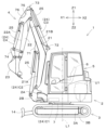
- FIG. 3 is a left side view of the working machine.
- FIG. 3 is a top view of the swivel table.
- FIG. 3 is a front perspective view of the working device.
- FIG. 3 is a partially exploded perspective view of the vicinity of the hydraulic cylinder. It is a downward sectional view of a cylinder cover.
- FIG. 3 is a front sectional view of the cylinder cover. It is a partially exploded perspective view of the periphery of a third cylinder bracket. It is a perspective view of the periphery of a third cylinder bracket. It is a downward sectional view of a cylinder cover showing other embodiments.
- the swivel base (aircraft body) 2 is supported on the upper part of the traveling device 3 via a swivel bearing 7 so as to be able to turn in the left-right direction. That is, the swivel base 2 is supported by the traveling device 3 so as to be rotatable around the swivel axis L1 (an axis extending in the vertical direction). Note that the pivot axis L1 is the rotation center of the pivot bearing 7.
- the working device 4 is provided on the front side of the swivel base 2, and is driven by hydraulic oil discharged from a hydraulic pump U2.
- the working device 4 is connected to a support bracket 2A provided at the front of the swivel base 2 via a swing bracket 2B.
- the swing bracket 2B is pivotally supported at the front part of the support bracket 2A so as to be swingable around a vertical axis (an axis extending in the vertical direction).
- the work device 4 has a boom 21, an arm 22, and a bucket (work tool) 23.
- a base end portion of the boom 21 is pivotably supported around a horizontal axis (an axis extending in the left-right direction) with respect to the swing bracket 2B. That is, the boom 21 is pivotally connected to the swing bracket 2B so as to be swingable in the vertical direction.
- the base end of the arm 22 is pivotally supported to the distal end of the boom 21 about a horizontal axis (an axis extending in the left-right direction). That is, the arm 22 is pivotally connected to the boom 21 so as to be swingable in the front-back direction and the up-down direction.
- the proximal end of the bucket 23 is pivotally supported to the distal end of the arm 22 about a horizontal axis (an axis extending in the left-right direction). That is, the bucket 23 is pivotally connected to the arm 22 so as to be capable of scooping and dumping operations.
- the work machine 1 can be equipped with another work tool (hydraulic attachment) that can be driven by hydraulic oil. Examples of other working tools include a hydraulic breaker, a hydraulic crusher, an angle broom, an earth auger, a pallet fork, a sweeper, a mower, and a snow blower.
- the working device 4 is driven by a hydraulic cylinder 24.
- the hydraulic cylinder 24 includes a swing cylinder C1, a boom cylinder C2, an arm cylinder C3, and a bucket cylinder (work implement cylinder) C4.
- the swing bracket 2B is swingable by the expansion and contraction of the swing cylinder C1.
- the boom 21 can be rocked by expanding and contracting the boom cylinder C2.
- the arm 22 can swing by expanding and contracting the arm cylinder C3.
- the bucket 23 is capable of scooping and dumping operations by expanding and contracting the bucket cylinder C4.
- the swing cylinder C1 is provided at the lower front side of the swivel base 2, and connects the body frame of the swivel base 2 and the swing bracket 2B.
- the boom cylinder C2 is provided on the lower base end side of the boom 21 (the front base end side of the boom 21 in an upwardly erected state), and is connected to the swing bracket 2B and the boom cylinder C2. 21 are connected.
- the arm cylinder C3 is provided on the top end side of the boom 21 (the rear end side of the boom 21 in an upwardly erected state), and connects the boom 21 and the arm 22.
- the bucket cylinder C4 is provided on the upper surface side of the arm 22 (the front side of the arm 22 in a downwardly bent state), and connects the arm 22 and the bucket 23.
- a cylinder cover 25 that protects the cylinder rod 32 of the hydraulic cylinder 24 is attached to the hydraulic cylinder 24.
- the cylinder covers 25 are provided at three locations: the boom cylinder C2, the arm cylinder C3, and the bucket cylinder C4, but they may be provided at two locations, the arm cylinder C3 and the bucket cylinder C4. , the boom cylinder C2, the arm cylinder C3, or the bucket cylinder C4.
- the bucket cylinder C4 includes a cylinder tube 31 and a cylinder rod 32.
- the cylinder tube 31 is a cylindrical body, and a base end 31e is connected to the front upper end of the bucket 23.
- the cylinder rod 32 is a cylindrical shaft body, and is inserted and held inside the cylinder tube 31 in a state of protruding from the distal end portion 31f of the cylinder tube 31 in the extending direction.
- the cylinder rod 32 is inserted into and held in the cylinder tube 31 so as to be slidable in the direction of extension of the axis L2.
- the cylinder rod 32 has a base end 32e inserted into the cylinder tube 31, and a distal end 32f connected to the front part of the arm 22.
- the working device 4 includes a first cylinder bracket 71, a second cylinder bracket 72, a third cylinder bracket (cylinder bracket) 73, and a fourth cylinder bracket 74.
- the first cylinder bracket 71 is provided on the first surface portion 21A of the circumferential surface of the boom 21.
- the second cylinder bracket 72 is provided on the second surface portion 21B of the circumferential surface of the boom 21.
- the third cylinder bracket 73 is provided at the base end of the arm 22.
- the fourth cylinder bracket 74 is provided at the base end of the bucket 23.
- the tip end 32f of the cylinder rod 32 is pivotally connected to the first cylinder bracket 71, and the base end 31e of the cylinder tube 31 is pivotally connected to the swing bracket 2B.
- the distal end 32f of the cylinder rod 32 is pivotally connected to the third cylinder bracket 73, and the base end 31e of the cylinder tube 31 is pivotally connected to the second cylinder bracket 72.
- the tip end 32f of the cylinder rod 32 is pivotally connected to the third cylinder bracket 73, and the base end 31e of the cylinder tube 31 is pivotally connected to the fourth cylinder bracket 74.
- the detailed structure of the third cylinder bracket 73 will be described later.
- the cylinder cover 25 of this embodiment includes a cover body 33 and a guide portion 25E.
- the guide portion 25E includes a guide plate 34 and an end cap (end portion) 35.
- the cover main body 33 is a long frame body with a flat, substantially U-shaped cross section, and extends in the same direction as the axis L2 on the front side of the bucket cylinder C4 (outside the cylinder rod 32), that is, in the same direction as the cylinder rod 32 (hydraulic cylinder 24). ) is stretched in the same direction as the stretching direction.
- the direction in which the cylinder rod 32 extends is the length direction of the cylinder cover 25, and the direction perpendicular to the direction in which the cylinder rod 32 extends and the width direction of the cover body 33 is defined as the cylinder.
- the width direction of the cover 25, which is perpendicular to the extending direction of the cylinder rod 32, and the thickness direction of the cover body 33 is referred to as the longitudinal width direction of the cylinder cover 25.
- the base end 33e of the cover body 33 is screwed and fixed to the connection J1 between the tip 32f of the cylinder rod 32 and the arm 22 with a bolt 38 from the normal direction of the support surface of the connection J1. That is, the cover main body 33 has a proximal end (first end side) 33e attached to the distal end side (connection part J1) of the cylinder rod 32 with a bolt 38, and moves together with the cylinder rod 32 as the hydraulic cylinder 24 expands and contracts. It is configured to be movable.
- the outer surface (cover outer surface) 33a which is the surface of the cover body 33 on the opposite side to the cylinder tube 31, has a V-shaped cross section that is convex outward in the vertical width direction (in the normal direction of the outer surface 33a).
- a reinforcing rib 36 is provided.
- the reinforcing rib 36 extends in the length direction along the center portion of the cover outer surface 33a in the width direction.
- the reinforcing ribs 36 are constructed as a separate member from the cover main body 33, and are fixed to the cover outer surface 33a by welding or the like, but they can be bent, pressed, etc.
- the cover outer surface 33a may be integrally formed in the center portion of the cover outer surface 33a in the width direction.
- a slide groove portion 37 having a U-shaped cross section is provided on the inner surface side of the cover body 33, which is the surface on the cylinder tube 31 side. The slide groove portion 37 extends in the length direction along the side edge portion 33b of the cover body 33 in the width direction, and opens toward the center side of the cover body 33 in the width direction (inward in the width direction).
- the guide plate 34 is a rectangular plate body elongated in the width direction of the cylinder cover 25, and is provided on the outer circumferential surface of the cylinder tube 31 so as to extend in a tangential direction to the outer circumference of a cross section perpendicular to the extending direction of the cylinder tube 31. There is. That is, the guide plate 34 is fixed to the cylinder tube 31 with both short side end surfaces (guide ends) 41 protruding from the outer peripheral surface of the cylinder tube 31 in the circumferential direction (see FIG. 6). An end cap 35 is attached to the guide end 41. As shown in FIG. 6, the guide end portions 41 are each inserted into the slide groove portion 37 from the center side (inside) in the width direction of the cover body 33. As shown in FIG.
- the cover main body 33 is engaged and held with respect to the cylinder cover 25 so as to be slidable in the length direction (direction of the axis L2).
- the end cap 35 has a first side surface (cap first side surface) 42, which is a surface opposite to the cylinder tube 31, in contact with a surface (first portion) 37a of the slide groove portion 37 on the opposite side to the cylinder tube 31.
- the second side surface (second side surface of the cap) 43 which is the surface on the cylinder tube 31 side, comes into contact with the surface (third portion) 37c on the cylinder tube 31 side.
- both the cap first side surface 42 and the cap second side surface 43 are formed in a planar shape.
- the end cap 35 is a flat cap body having an insertion hole in the inner end surface 44 for inserting the guide plate 34, and is fixed by covering the guide end 41.
- the tangential end surface (cap end surface) 45 of the end cap 35 has a shape that is convex toward the groove inner side surface 37b of the slide groove 37 when viewed from the normal direction of the plate surface of the guide plate 34. It is formed into a substantially V-shape.
- the first curved convex surface portion 51 which is the protruding end portion of the cap end surface 45, is curved in an arc shape so that the shape viewed from the normal direction of the plate surface of the guide plate 34 is convex toward the groove inner side surface portion 37b of the slide groove portion 37. has been done.
- the distance W1 between the first curved convex surface portions 51 of the cap end surfaces 45 on both sides in the tangential direction (dimension between the cap ends) is determined from the distance W2 between the inner groove side surfaces 37b on both sides in the tangential direction (dimension between the inner groove side surfaces) W2. is also set small.
- the inclined surface portion 52 is formed continuously from the outer circumferential arc curved surface of the first curved convex surface portion 51 in the tangential direction thereof.
- a corner 53 of the cap end face 45 on the side opposite to the cylinder tube 31 and a corner 54 on the side of the cylinder tube 31 are both formed into approximately 45-degree tapered surfaces. That is, the cap end surface 45 is formed in such a shape that both a corner 53 on the opposite side to the cylinder tube 31 and a corner 54 on the cylinder tube 31 side in a cross section perpendicular to the extending direction of the cylinder rod 32 are chamfered. Therefore, a predetermined gap is defined between the corner portions 53 and 54 and the inner corner portion of the slide groove portion 37.
- the end cap 35 is formed of a synthetic resin material such as vinyl chloride resin or polycarbonate resin.
- the cover body 33 is made of a metal material such as iron or stainless steel. That is, the end cap 35 and the cover body 33 are made of different materials. Further, the end cap 35 may be formed of an elastic member. Thereby, noise, damage, deformation, etc. caused by friction or contact between the end cap 35 and the cover main body 33 can be suppressed.
- the third cylinder bracket (cylinder bracket) 73 includes a bracket side plate 75 and a cover plate 76.
- the bracket side plates 75 are substantially flat plate bodies, and are provided in pairs on the first surface portion 22A of the circumferential surface of the arm 22, spaced apart from each other in the left and right directions.
- the distal end portion 32f of the cylinder rod 32 of the arm cylinder C3 and the distal end portion 32f of the cylinder rod 32 of the bucket cylinder C4 are each pivotally supported while being sandwiched between the bracket side plates 75.
- the bracket side plate 75 is formed of a thick metal plate with high bending rigidity so as not to bend due to the stress applied from the arm cylinder C3 and the bucket cylinder C4 while the working device 4 is being driven.
- a hydraulic hose 56 for guiding hydraulic oil to each hydraulic cylinder 24, and the like are housed in the space S1 between the bracket side plates 75. ing. Therefore, the bracket side plate 75 also has the effect of protecting the potentiometer 55, hydraulic hose 56, etc. from collision with external objects.
- the bracket side plate 75 has a hollowed out portion 77.
- the lightened portion 77 of this embodiment is a notch formed in the tip edge 75a of the bracket side plate 75 in a substantially arc shape when viewed from the normal direction of the plate surface of the bracket side plate 75.
- the hollowed out portion 77 is formed in a position and size that does not overlap with the arrangement portions of the potentiometer 55, hydraulic hose 56, etc. when viewed from the normal direction of the plate surface of the bracket side plate 75.
- the hollowed out portion 77 may be a through hole that penetrates between the plate surfaces of the bracket side plates 75.
- a cover support portion 78 is installed horizontally between the left and right bracket side plates 75.
- the cover support portion 78 is a substantially flat plate, and is supported and fixed to the surface of each bracket side plate 75 on the side of the separation portion S1.
- the cover support portion 78 is provided with a screw hole 80 into which a cover fixing screw 79 can be screwed.
- the cover fixing screw 79 is screwed into the screw hole 80 from the normal direction of the plate surface of the cover support portion 78 with the cover plate 76 interposed therebetween. That is, the cover plate 76 is connected and fixed to the cover support part 78 by cover fixing screws 79.
- the cover support portions 78 are disposed at a position closer to the tip end 32f of the cylinder rod 32 of the arm cylinder C3, and at a position closer to the tip edge 75a of the bracket side plate 75 at the tip end 32f of the cylinder rod 32 of the bucket cylinder C4. There is.
- the cover support portions 78 on the bucket cylinder C4 side are arranged in line on the outer side in the extending direction of the cover body 33 (on the center side of the third cylinder bracket 73) than the base end portion 33e of the cylinder cover 25. That is, the cover support portion 78 is provided at a position that does not overlap with the attachment portion of the bolt 38 when viewed from the axial direction (first direction) of the bolt 38 that attaches the base end portion 33e of the cylinder cover 25 to the connection portion J1.
- the cover plate 76 is a metal plate that is thinner and lighter than the bracket side plate 75, and is supported and fixed along the inside of the tip edge 75a of the bracket side plate 75.
- the cover plate 76 covers the spaced apart portion S1 between the bracket side plates 75 from the tip edge 75a side of the bracket side plates 75.
- the cover plate 76 includes a cover body 81, a fixing piece 82, and a lid piece 83.
- the cover main body 81 is formed into a rectangular flat plate shape whose left-right width dimension is approximately the same as that of the separating portion S1.
- the fixing pieces 82 are rectangular flat plate pieces, and are provided on both short edges of the cover body 81, respectively.
- the fixing piece 82 has a screw insertion hole 84 into which the cover fixing screw 79 can be inserted.
- the fixing piece 82 is supported by the cover support part 78 in a face-to-face state, and is fixed by the cover fixing screw 79. That is, as shown in FIG. 9, the cover plate 76 does not overlap the mounting portion of the bolt 38 when viewed from the axial direction (first direction) of the bolt 38 that fixes the base end portion 33e of the cylinder cover 25 to the connecting portion J1. Fixed in position. Thereby, the cylinder cover 25 can be replaced without removing the cover plate 76 from the cover support part 78.
- the lid pieces 83 are plate pieces having edge shapes that are approximately the same as the hollowed out portions 77 of the bracket side plates 75, and are provided on both long edges of the cover body 81, respectively.
- the lid piece 83 is bent toward one plate surface side of the cover body 81.
- the lid piece 83 is formed in a substantially arc shape when viewed from the normal direction of the plate surface of the bracket side plate 75, and when the cover plate 76 is attached to the bracket side plate 75 as described above, the hollowed out portion 77 from the inside of the bracket side plate 75. Thereby, it is possible to suppress foreign matter such as dirt and dust from entering the separation portion S1.
- each of the lid pieces 83 is bent approximately 90 degrees in the direction normal to one plate surface of the cover body 81. This allows the cover plate 76 to have higher rigidity than a simple flat plate. Furthermore, when the cover plate 76 is attached to the bracket side plate 75, the lid piece 83 is pressed against the inside of the bracket side plate 75 by its restoring force against bending. That is, the lid piece 83 can cover the hollowed out portion 77 in close contact with the inside of the bracket side plate 75. This makes it possible to more effectively suppress foreign matter from entering the spaced portion S1.
- the first curved convex surface portion 51 is formed in an arc shape having the same diameter as the end-to-end dimension W1 of the cap, but if it is possible to reduce the contact resistance between the end cap 35 and the slide groove portion 37, It may be formed into a circular arc shape (for example, a semicircular small diameter convex shape) with a diameter smaller than the end-to-end dimension W1.
- the first curved convex surface portions 51 of the end caps 35 on both sides in the tangential direction are formed in a concentric arc shape, but it is possible to reduce the contact resistance between the end caps 35 and the slide groove portions 37.
- the first curved convex surface portions 51 of the end caps 35 on both sides in the tangential direction are eccentrically formed in the extending direction of the cylinder rod 32 or in the direction perpendicular to the extending direction when viewed from the normal direction of the plate surface of the guide plate 34. may be done.
- the cap end surface 45 is formed in a V shape when viewed from the normal direction of the plate surface of the guide plate 34, and the adjacent surface portions (inclined Although the surface portion) 52 forms an inclined surface, when an angular deviation occurs in the extending direction of the slide groove portion 37 with respect to the guide plate 34, a portion of the end cap 35 other than the first curved convex surface portion 51 becomes the groove inner side surface portion 37b.
- the adjacent surface portion 52 may be formed in a planar shape substantially parallel to the groove inner side surface portion 37b, as long as it is possible to suppress contact with the groove inner side surface portion 37b.
- the end cap 35 has a surface opposite to the cylinder tube 31 (cap first side surface) 42 and a surface on the cylinder tube 31 side (cap second side surface) 43 each formed into a planar shape, and the slide groove portion 37
- a second curved convex surface portion 61 may be provided that is curved so as to be convex in the normal direction of the plate surface. Further, the second curved convex surface portion 61 may have an arcuate cross-section perpendicular to the direction in which the cylinder rod 32 extends.
- end caps (end portions) 35 are attached to both ends of the guide plate 34
- the configuration of the end portions is not limited to this.
- the end portion may have a shape different from the cap shape, or the end portion may be formed integrally with the guide plate 34.
- the gap between the end surface 45 of the end portion 35 and the second portion (groove inner side surface portion) 37b of the cover body 33 can be reduced, and the contact resistance between the end surface 45 and the second portion 37b can be reduced. This makes it possible to suppress the occurrence of abnormal noises and vibrations, and also enables smooth operation.
- the first curved convex surface portion 51 is a part of a circle having a smaller diameter than the second portion (groove inner side surface portion) 37b provided on both sides of the cover main body 33 in the tangential direction. It is formed in the shape of a circular arc.
- the radius of curvature of the first curved convex surface portion 51 is large, the contact area becomes large depending on the material of the end portion 35 as it deforms.
- the contact area between the end portion 35 and the cover main body 33 can be reduced, so that smoother operation can be achieved.
- first curved convex surface portions 51 of each end portion 35 provided on both sides in the tangential direction are formed in a concentric arc shape. According to this configuration, the stress when the first curved convex surface portion 51 of each end portion 35 contacts the second portion 37b is concentrated in the same central direction, so that displacement in the sliding direction of the cover body 33 is unlikely to occur. . Therefore, the occurrence of abnormal noise and vibration can be suppressed, and smoother operation is also possible.
- the end surface 45 has an inclined surface on both sides of the first curved convex surface section 51 in the extending direction of the cylinder rod 32 such that the further away from the first curved convex surface section 51 in the extending direction of the cylinder rod 32 the further away from the second portion 37b. It has a surface portion 52. According to this configuration, even if an angular deviation occurs in the extending direction of the cover body 33 with respect to the guide plate 34, the end portion 35 other than the first curved convex surface portion 51 is unlikely to come into contact with the second portion 37b. The contact resistance between the portion 35 and the cover body 33 can be reduced. Therefore, the occurrence of abnormal noise and vibration can be further suppressed, and smoother operation is also possible.
- the working device 4 has a cylinder bracket 73 that supports the first end 32f on the distal end side of the cylinder rod 32, and the cylinder bracket 73 is spaced apart in one direction and is erected to support the first end 32f. and a cover plate 76 that covers the spaced apart part S1 between the bracket side plates 75, the bracket side plate 75 has a hollowed out part 77, and the cover plate 76 has a hollowed out part It has a lid piece 83 that covers 77.
- the lid piece 83 is formed by bending a part of the cover plate 76.
- the overall rigidity of the cover plate 76 can be increased, making it possible to further reduce the weight of the cylinder bracket 73. .
- the cylinder cover 25 can be attached and removed without removing the cover plate 76 from the cover support part 78, so that maintenance efficiency is improved.
- the hollowed out portion 77 is a notch formed in the tip edge 75a of the bracket side plate 75.
- the work machine 1 includes a machine body 2 and a work device 4 attached to the machine body 2, and the work device 4 supports a hydraulic cylinder 24 that drives the work device 4 and a first end 32f of the hydraulic cylinder 24.
- the cylinder bracket 73 has a pair of bracket side plates 75 that are spaced apart in one direction and sandwich the first end 32f, and a spaced apart part S1 between the bracket side plates 75.
- the bracket side plate 75 has a hollowed-out portion 77
- the cover plate 76 has a lid piece 83 that covers the hollowed-out portion 77 .
- the present invention is not limited to this, and for example, a wheel loader, a compact track loader, a skid steer loader, etc. It may also be applied to other construction machines such as tractors, combines, rice transplanters, lawn mowers, and other agricultural machines.
Landscapes
- Engineering & Computer Science (AREA)
- General Engineering & Computer Science (AREA)
- Physics & Mathematics (AREA)
- Fluid Mechanics (AREA)
- Mechanical Engineering (AREA)
- Mining & Mineral Resources (AREA)
- Civil Engineering (AREA)
- Structural Engineering (AREA)
- Actuator (AREA)
Priority Applications (3)
| Application Number | Priority Date | Filing Date | Title |
|---|---|---|---|
| EP23831480.1A EP4549664A1 (en) | 2022-06-30 | 2023-06-28 | Cylinder cover, hydraulic cylinder, and work machine |
| JP2024530901A JPWO2024005040A1 (https=) | 2022-06-30 | 2023-06-28 | |
| US18/975,185 US12534881B2 (en) | 2022-06-30 | 2024-12-10 | Cylinder cover, hydraulic cylinder, and working machine |
Applications Claiming Priority (2)
| Application Number | Priority Date | Filing Date | Title |
|---|---|---|---|
| JP2022105782 | 2022-06-30 | ||
| JP2022-105782 | 2022-06-30 |
Related Child Applications (1)
| Application Number | Title | Priority Date | Filing Date |
|---|---|---|---|
| US18/975,185 Continuation US12534881B2 (en) | 2022-06-30 | 2024-12-10 | Cylinder cover, hydraulic cylinder, and working machine |
Publications (1)
| Publication Number | Publication Date |
|---|---|
| WO2024005040A1 true WO2024005040A1 (ja) | 2024-01-04 |
Family
ID=89382335
Family Applications (1)
| Application Number | Title | Priority Date | Filing Date |
|---|---|---|---|
| PCT/JP2023/023886 Ceased WO2024005040A1 (ja) | 2022-06-30 | 2023-06-28 | シリンダカバー、油圧シリンダ、および作業機 |
Country Status (4)
| Country | Link |
|---|---|
| US (1) | US12534881B2 (https=) |
| EP (1) | EP4549664A1 (https=) |
| JP (1) | JPWO2024005040A1 (https=) |
| WO (1) | WO2024005040A1 (https=) |
Citations (10)
| Publication number | Priority date | Publication date | Assignee | Title |
|---|---|---|---|---|
| JPH03103352U (https=) * | 1990-02-13 | 1991-10-28 | ||
| JPH03128748U (https=) * | 1990-04-03 | 1991-12-25 | ||
| JPH0587041U (ja) * | 1991-09-26 | 1993-11-22 | セイレイ工業株式会社 | バックホーブームのシリンダー支持構造 |
| JPH08296611A (ja) * | 1995-04-26 | 1996-11-12 | Kobelco Kenki Eng Kk | 油圧シリンダの保護装置 |
| JP2001073404A (ja) * | 1999-09-06 | 2001-03-21 | Hitachi Constr Mach Co Ltd | シリンダカバー装置 |
| JP2001073405A (ja) * | 1999-09-06 | 2001-03-21 | Hitachi Constr Mach Co Ltd | シリンダカバー装置 |
| JP2002220853A (ja) * | 2001-01-23 | 2002-08-09 | Kubota Corp | シリンダの保護装置 |
| JP2005320848A (ja) * | 2004-05-04 | 2005-11-17 | Volvo Construction Equipment Holding Sweden Ab | 異音を防止するシリンダ保護装置 |
| JP2008095297A (ja) * | 2006-10-06 | 2008-04-24 | Hitachi Constr Mach Co Ltd | 建設機械 |
| JP2020101058A (ja) | 2018-12-25 | 2020-07-02 | 株式会社クボタ | 作業機 |
Family Cites Families (11)
| Publication number | Priority date | Publication date | Assignee | Title |
|---|---|---|---|---|
| US2764303A (en) * | 1954-07-01 | 1956-09-25 | Sr John R Austin | Piston rod guard for material handling apparatus |
| JPH0657970A (ja) * | 1992-08-10 | 1994-03-01 | Ooyodo Diesel Kk | コンクリート破砕機 |
| JPH10292426A (ja) * | 1997-04-18 | 1998-11-04 | Komatsu Ltd | 油圧シリンダの保護装置 |
| DE60045471D1 (de) * | 1999-02-09 | 2011-02-17 | Yanmar Co Ltd | Hydraulisch angetriebene arbeitsmaschine |
| JP4695340B2 (ja) * | 2004-03-10 | 2011-06-08 | 日立建機株式会社 | ブームシリンダのカバー装置 |
| JP4038197B2 (ja) * | 2004-07-01 | 2008-01-23 | ヤンマー株式会社 | シリンダの保護装置 |
| KR20150114706A (ko) * | 2014-04-02 | 2015-10-13 | 현대중공업 주식회사 | 건설기계의 유압배관 보호장치 |
| EP2933388B1 (en) * | 2014-04-18 | 2020-11-11 | Caterpillar Work Tools B. V. | Hydraulic cylinder cover |
| JP6509693B2 (ja) * | 2015-09-11 | 2019-05-08 | 株式会社日立建機ティエラ | シリンダ装置 |
| CN112771232B (zh) * | 2018-12-25 | 2022-09-09 | 株式会社久保田 | 作业机 |
| CA3155250A1 (en) * | 2019-10-25 | 2021-04-29 | Robert Ray | A hydraulic cylinder piston rod protection system |
-
2023
- 2023-06-28 JP JP2024530901A patent/JPWO2024005040A1/ja active Pending
- 2023-06-28 EP EP23831480.1A patent/EP4549664A1/en active Pending
- 2023-06-28 WO PCT/JP2023/023886 patent/WO2024005040A1/ja not_active Ceased
-
2024
- 2024-12-10 US US18/975,185 patent/US12534881B2/en active Active
Patent Citations (10)
| Publication number | Priority date | Publication date | Assignee | Title |
|---|---|---|---|---|
| JPH03103352U (https=) * | 1990-02-13 | 1991-10-28 | ||
| JPH03128748U (https=) * | 1990-04-03 | 1991-12-25 | ||
| JPH0587041U (ja) * | 1991-09-26 | 1993-11-22 | セイレイ工業株式会社 | バックホーブームのシリンダー支持構造 |
| JPH08296611A (ja) * | 1995-04-26 | 1996-11-12 | Kobelco Kenki Eng Kk | 油圧シリンダの保護装置 |
| JP2001073404A (ja) * | 1999-09-06 | 2001-03-21 | Hitachi Constr Mach Co Ltd | シリンダカバー装置 |
| JP2001073405A (ja) * | 1999-09-06 | 2001-03-21 | Hitachi Constr Mach Co Ltd | シリンダカバー装置 |
| JP2002220853A (ja) * | 2001-01-23 | 2002-08-09 | Kubota Corp | シリンダの保護装置 |
| JP2005320848A (ja) * | 2004-05-04 | 2005-11-17 | Volvo Construction Equipment Holding Sweden Ab | 異音を防止するシリンダ保護装置 |
| JP2008095297A (ja) * | 2006-10-06 | 2008-04-24 | Hitachi Constr Mach Co Ltd | 建設機械 |
| JP2020101058A (ja) | 2018-12-25 | 2020-07-02 | 株式会社クボタ | 作業機 |
Also Published As
| Publication number | Publication date |
|---|---|
| US12534881B2 (en) | 2026-01-27 |
| JPWO2024005040A1 (https=) | 2024-01-04 |
| EP4549664A1 (en) | 2025-05-07 |
| US20250101998A1 (en) | 2025-03-27 |
Similar Documents
| Publication | Publication Date | Title |
|---|---|---|
| US8960725B2 (en) | Hollow fender | |
| JP4650571B2 (ja) | 油圧破砕機 | |
| JP5204911B1 (ja) | ブルドーザ | |
| KR100908366B1 (ko) | 실린더의 보호 장치 | |
| US20130193665A1 (en) | Fender assembly | |
| WO2024005040A1 (ja) | シリンダカバー、油圧シリンダ、および作業機 | |
| JP2013237996A (ja) | 建設機械 | |
| JP5046138B2 (ja) | アタッチメントホースのクランプ構造 | |
| KR20200120332A (ko) | 굴삭기 | |
| JP5502013B2 (ja) | 伸縮式トラックフレーム | |
| JP4695340B2 (ja) | ブームシリンダのカバー装置 | |
| JP4542019B2 (ja) | シリンダ装置 | |
| JP6581065B2 (ja) | 作業機械 | |
| JPH11200409A (ja) | スイング式作業機の可撓管の配置構造 | |
| US20260092432A1 (en) | Work machine | |
| JP6868940B2 (ja) | 建設機械 | |
| JP2001073405A (ja) | シリンダカバー装置 | |
| JP2004162292A (ja) | バケットシリンダ保護装置 | |
| JP7677919B2 (ja) | 建設機械 | |
| JP3788870B2 (ja) | 超小旋回作業機 | |
| WO2019235334A1 (ja) | 作業機 | |
| JP7345536B2 (ja) | 作業機械 | |
| EP4053344B1 (en) | A coupling device for a work machine | |
| JP2024127540A (ja) | 作業機械 | |
| JP3978163B2 (ja) | 超小旋回作業機 |
Legal Events
| Date | Code | Title | Description |
|---|---|---|---|
| 121 | Ep: the epo has been informed by wipo that ep was designated in this application |
Ref document number: 23831480 Country of ref document: EP Kind code of ref document: A1 |
|
| WWE | Wipo information: entry into national phase |
Ref document number: 2024530901 Country of ref document: JP |
|
| WWE | Wipo information: entry into national phase |
Ref document number: 2023831480 Country of ref document: EP |
|
| NENP | Non-entry into the national phase |
Ref country code: DE |
|
| ENP | Entry into the national phase |
Ref document number: 2023831480 Country of ref document: EP Effective date: 20250130 |
|
| WWP | Wipo information: published in national office |
Ref document number: 2023831480 Country of ref document: EP |