WO2023276139A1 - Structure support élastique - Google Patents
Structure support élastique Download PDFInfo
- Publication number
- WO2023276139A1 WO2023276139A1 PCT/JP2021/025111 JP2021025111W WO2023276139A1 WO 2023276139 A1 WO2023276139 A1 WO 2023276139A1 JP 2021025111 W JP2021025111 W JP 2021025111W WO 2023276139 A1 WO2023276139 A1 WO 2023276139A1
- Authority
- WO
- WIPO (PCT)
- Prior art keywords
- support structure
- elastic support
- flat plate
- tip
- connecting portion
- Prior art date
Links
- 238000013459 approach Methods 0.000 claims description 32
- 230000002093 peripheral effect Effects 0.000 claims description 8
- 230000000149 penetrating effect Effects 0.000 claims description 4
- 230000000052 comparative effect Effects 0.000 description 11
- 230000006835 compression Effects 0.000 description 6
- 238000007906 compression Methods 0.000 description 6
- 238000010146 3D printing Methods 0.000 description 2
- 238000010586 diagram Methods 0.000 description 2
- 230000000694 effects Effects 0.000 description 2
- 238000000071 blow moulding Methods 0.000 description 1
- 238000005266 casting Methods 0.000 description 1
- 238000005520 cutting process Methods 0.000 description 1
- 230000007423 decrease Effects 0.000 description 1
- 238000006073 displacement reaction Methods 0.000 description 1
- 238000001125 extrusion Methods 0.000 description 1
- 238000005242 forging Methods 0.000 description 1
- 230000012447 hatching Effects 0.000 description 1
- 238000001746 injection moulding Methods 0.000 description 1
- 239000000463 material Substances 0.000 description 1
- 239000007769 metal material Substances 0.000 description 1
- 238000003825 pressing Methods 0.000 description 1
- 230000001105 regulatory effect Effects 0.000 description 1
- 239000011347 resin Substances 0.000 description 1
- 229920005989 resin Polymers 0.000 description 1
Images


Classifications
-
- F—MECHANICAL ENGINEERING; LIGHTING; HEATING; WEAPONS; BLASTING
- F16—ENGINEERING ELEMENTS AND UNITS; GENERAL MEASURES FOR PRODUCING AND MAINTAINING EFFECTIVE FUNCTIONING OF MACHINES OR INSTALLATIONS; THERMAL INSULATION IN GENERAL
- F16F—SPRINGS; SHOCK-ABSORBERS; MEANS FOR DAMPING VIBRATION
- F16F1/00—Springs
- F16F1/36—Springs made of rubber or other material having high internal friction, e.g. thermoplastic elastomers
- F16F1/366—Springs made of rubber or other material having high internal friction, e.g. thermoplastic elastomers made of fibre-reinforced plastics, i.e. characterised by their special construction from such materials
- F16F1/368—Leaf springs
Definitions
- the present invention relates to elastic support structures.
- a plate-shaped spring has been proposed that includes a body portion that is configured in a zigzag shape and has plate portions that are bent in multiple stages, one end portion on one end side of the body portion, and the other end portion on the other end side of the body portion. (See Patent Document 1).
- the plate-shaped spring described above When the plate-shaped spring described above is used as a compression spring that is compressed along the axial direction, contact (self-contact) between one end and the opposing plate in the compression direction, or between the other end and the opposite Further approach between the one end and the other end is regulated by the contact with the adjacent plate portion and the contact between the two plate portions facing each other. If the two are restricted from approaching each other further, they become similar to a rigid body as a whole, and the vibration absorbing function deteriorates. In particular, when the rigidity of the plate-shaped spring in the axial direction is low, in the initial state, each end may bend due to its own weight and come close to the plate, and when a load is applied from that state, , the allowable displacement that can be effectively obtained is even smaller.
- the main purpose of the elastic support structure of the present invention is to increase the allowable amount of approach of both ends in the axial direction.
- the elastic support structure of the present invention employs the following means in order to achieve the above main objectives.
- the elastic support structure of the present invention includes: a flat plate portion extending along a direction orthogonal to the axis; a first beam portion connected to a first portion of the outer peripheral portion of the flat plate portion via a first connecting portion and extending toward the axial side with a gap from a first surface in the axial direction of the flat plate portion; The outer peripheral portion of the flat plate portion is connected to the second portion on the opposite side of the first portion across the axis through a second connecting portion, and is spaced from the second surface of the flat plate portion in the axial direction.
- a resilient support structure comprising: The flat plate portion has a first recess recessed from the first surface so that at least the tip portion of the first beam portion can enter when the first beam portion approaches the second beam portion, and the first recess portion is recessed from the first surface. a second recess that is recessed from the second surface so that at least the tip portion of the second beam can enter when the two beams approach the first beam; This is the gist of it.
- the flat plate portion has the first concave portion recessed from the first surface so that at least the tip portion of the first beam portion can enter when the first beam portion approaches the second beam portion. and a second recess recessed from the second surface so that at least the tip of the second beam can enter when the second beam approaches the first beam. Therefore, when the front end portion of the first beam portion and the front end portion of the second beam portion approach each other due to an external force in the compression direction, at least the front end portion of the first beam portion enters the first recess and the second beam portion can enter the second recess. As a result, the allowable amount of approach between the tip of the first beam and the tip of the second beam from the initial state is increased compared to when the flat plate does not have the first recess and the second recess. can be done.
- the first concave portion and the second concave portion may form a through hole penetrating in the axial direction by communicating with each other.
- the through hole may be formed so that the first beam portion and the second beam portion can contact each other.
- the width of the tip portion of the first beam portion and the width of the tip portion of the second beam portion are formed to be narrower than the width of the flat plate portion. good too.
- the first beam portion is formed so that the width becomes narrower from the first connecting portion side toward the tip portion side
- the second beam portion is formed so as to extend from the second connecting portion side to the tip portion side. It may be formed such that the width becomes narrower toward the tip side.
- a plurality of the first beam portions extend toward the axis line at intervals in the width direction of the first connecting portion, and the second beam portion extends from the second connecting portion.
- a plurality of first recesses are formed so as to be able to enter at least the tip end portions of the plurality of first beam portions, and the plurality of second recesses are formed so as to be able to enter the plurality of first recesses.
- At least the tip portion of the second beam portion may be formed in plurality so as to be able to enter.
- the first concave portion has a first inclined surface that is inclined toward the first connecting portion side from the second surface side toward the first surface side, and the second concave portion is and a second inclined surface inclined toward the second connecting portion from the first surface side toward the second surface side.
- the flat plate portion, the first beam portion, and the second beam portion may be formed so as to be parallel to each other. Further, the first beam portion and the second beam portion are formed so as to be point-symmetrical to each other with respect to a predetermined point in the flat plate portion, and the first connecting portion and the second connecting portion They may be formed so as to be symmetrical with each other with respect to a predetermined point.
- a plurality of elastic elements having the flat plate portion, the first beam portion, and the second beam portion may be connected in series along the axial direction.
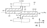
- FIG. 1 is an external perspective view of an elastic support structure 20 as one embodiment of the present invention
- FIG. 2 is a cross-sectional view of the elastic support structure 20
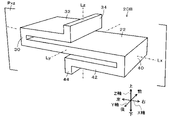
- FIG. 11 is an external perspective view of an elastic support structure 20B of a comparative example
- FIG. 11 is a cross-sectional view of an elastic support structure 20B of a comparative example
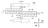
- FIG. 5 is an explanatory diagram showing an example of how the first beam portion 32 and the second beam portion 42 of the elastic support structures 20 and 20B of the example and the comparative example approach each other
- FIG. 4 is a cross-sectional view of a modified elastic support structure 120
- FIG. 11 is a cross-sectional view of a modified elastic support structure 220
- FIG. 11 is a cross-sectional view of a modified elastic support structure 320;
- FIG. 11 is an external perspective view of an elastic support structure 420 of a modified example;
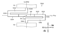
- FIG. 11 is an external perspective view of an elastic support structure 520 of a modified example;
- FIG. 11 is a rear view of a modified elastic support structure 520;
- FIG. 11 is an external perspective view of an elastic support structure 620 of a modified example;
- FIG. 6 is a cross-sectional view of a modified elastic support structure 620;
- FIG. 1 is an external perspective view of an elastic support structure 20 as one embodiment of the present invention
- FIG. 2 is a cross-sectional view of the elastic support structure 20.
- the horizontal direction is the X-axis direction
- the front-rear direction is the Y-axis direction (the width direction of the elastic support structure 20)
- the vertical direction is the Z-axis direction (the height direction of the elastic support structure 20).
- the straight lines extending in the X-, Y-, and Z-axis directions through the center Cn in the X-, Y-, and Z-axis directions of the elastic support structure 20 are referred to as axis lines Lx, Ly, and Lz, respectively.
- FIG. 2 is a cross-sectional view of the elastic support structure 20 of FIG. 1 taken along the predetermined XZ plane Pxz. Note that the arrangement of the elastic support structure 20 is not limited to the orientation shown in FIG.
- the elastic support structure 20 of the embodiment is integrally molded, for example, by injection molding, blow molding, extrusion molding, or 3D printing of resin materials, or casting, forging, pressing, cutting, or 3D printing of metal materials.
- the elastic support structure 20 is arranged between the base member 10 and the mount member 12 in the Z-axis direction, and supported by the base member 10 and the mount member 12, as shown in FIG.
- the elastic support structure 20 includes a flat plate portion 22, a first connecting portion 30, a first beam portion 32, a first shaft portion 34, a second connecting portion 40, and a second connecting portion 40. It has two beam portions 42 and a second shaft portion 44 .
- the elastic support structure 20 is formed so as to be a mirror image of a predetermined XZ plane Pxz (a plane including the axes Lx and Lz), and the axis Lz is the tip of the first shaft portion 34 and the first beam portion 32. , the central portion of the flat plate portion 22 (a through hole 26 to be described later), the tip portion of the second beam portion 42 , and the second shaft portion 44 .
- the elastic support structure 20 is rotationally symmetrical (two-fold symmetrical) with respect to the axis Ly (point-symmetrically with respect to the center Cn in the predetermined XZ plane), specifically, the first joint The portion 30 and the second connecting portion 40, the first beam portion 32 and the second beam portion 42, and the first shaft portion 34 and the second shaft portion 44 are formed to be rotationally symmetrical.
- the flat plate portion 22 is formed in a rectangular plate shape extending in the XY directions so as to be a mirror image with respect to the predetermined YZ plane Pyz.
- a rectangular through-hole 26 penetrating in the Z-axis direction is formed in the central portion of the flat plate portion 22 so as to be a mirror image with respect to the predetermined YZ plane Pyz.
- Front and rear inner wall surfaces of the rectangular through-hole 26 extend along the XZ plane so as to face each other, and extend toward the first connecting portion 30 side (left side) and the second connecting portion 40 side.
- the (right) inner wall surfaces extend along the YZ plane and face each other.
- the first connecting portion 30 has the same width (length in the Y direction) as the flat plate portion 22 and extends upward in the Z-axis direction from the left end (first portion) of the outer peripheral portion of the flat plate portion 22 in the X-axis direction. is served.
- the first beam portion 32 extends from the upper end portion of the first connecting portion 30 to the upper surface 23 of the flat plate portion 22 and parallel to the flat plate portion 22, and extends around the axis Lz toward the right end side in the X-axis direction. has been extended to
- the first beam portion 32 is formed so that the width of the first beam portion 32 decreases from the base end portion side (first connecting portion 30 side) toward the tip portion side. It is narrower than the width of 26.
- the first shaft portion 34 extends upward in the Z-axis direction from the distal end portion of the first beam portion 32 and abuts or is fixed to the mount member 12 .
- the second connecting portion 40 has the same width (length in the Y direction) as the flat plate portion 22 and extends downward in the Z-axis direction from the right end (second portion) of the outer peripheral portion of the flat plate portion 22 in the X-axis direction. has been deferred.
- the second beam portion 42 extends from the lower end portion of the second connecting portion 40 to the lower surface 24 of the flat plate portion 22 and is parallel to the flat plate portion 22 and extends around the axis Lz toward the left end side in the X-axis direction. has been extended to
- the second beam portion 42 is formed so that the width of the second beam portion 42 becomes narrower from the base end portion side (the second connecting portion 40 side) toward the tip portion side. It is narrower than the width of 26.
- the width of the through hole 26, the tip of the first beam portion 32, and the tip portion of the second beam portion 42 are designed in consideration of the rigidity of the flat plate portion 22, the first beam portion 32, and the second beam portion 42. be done.
- the second shaft portion 44 extends downward in the Z-axis direction from the distal end portion of the second beam portion 42 and abuts or is fixed to the base member 10 .
- FIG. 3 is an external perspective view of an elastic support structure 20B of a comparative example
- FIG. 4 is a cross-sectional view of the elastic support structure 20B of a comparative example. 3 and 4 correspond to FIGS. 1 and 2, respectively.
- the elastic support structure 20B of the comparative example does not have the through hole 26, and has the flat plate portion 22, the first connecting portion 30, the first beam portion 32, the first shaft portion 34, the second connecting portion 40 and the second beam portion. 42 and the second shaft portion 44 are formed to have the same width (length in the Y-axis direction), which is different from the elastic support structure 20 of the embodiment.
- the elastic support structure 20 of the example and the elastic support structure 20B of the comparative example have different rigidity characteristics. Therefore, the thickness of each part of the elastic support structure 20 is adjusted in order to compensate for the same rigidity as that of the elastic support structure 20B.
- FIG. 5 is an explanatory diagram showing an example of how the first beam portions 32 and the second beam portions 42 of the elastic support structures 20 and 20B of the embodiment and the comparative example approach each other.
- the solid line indicates the elastic support structure 20 of the example
- the dashed line indicates the elastic support structure 20B of the comparative example. Note that hatching is omitted in FIG. 5 for ease of viewing.
- the first beam portion 32, and the second beam portion 42 can be brought closer together. Then, when the tip of the first beam portion 32 contacts the upper surface 23 of the flat plate portion 22 and the tip of the second beam portion 42 contacts the lower surface 24 of the flat plate portion 22, the entire body becomes similar to a rigid body and vibrates.
- the tip of the first beam 32 and the tip of the second beam 42 can approach each other until the upper surface of the second beam 42 abuts the edge of the through hole 26 on the lower surface 24 side.
- the first beam portion 32 and the second beam portion 42 may be separated from each other until the tip portion of the first beam portion 32 and the tip portion of the second beam portion 42 are in contact with each other.
- the tip portion and the tip portion of the second beam portion 42 can approach each other. In the latter case, compared with the former case, the allowable amount of approach between the tip of the first beam portion 32 and the tip of the second beam portion 42 from the initial state can be increased.
- the elastic support structure 20 of the embodiment is formed so as to be a mirror image with respect to the predetermined XZ plane Pxz, and is rotationally symmetrical (two-fold symmetrical) with respect to the axis Ly.
- the first connecting portion 30 and the second connecting portion 40, the first beam portion 32 and the second beam portion 42, and the first shaft portion 34 and the second shaft portion 44 are formed to be rotationally symmetrical.
- the flat plate portion 22 has a through hole 26 penetrating in the Z-axis direction at its central portion.
- the flat plate portion 22 is formed in a rectangular plate shape.
- the shape is not limited to this, and for example, the flat plate portion 22 may be formed in a disk shape, an elliptical plate shape, or the like.
- the rectangular through-hole 26 of the flat plate portion 22 is positioned on the first connecting portion 30 side (left side) and on the second connecting portion 40 side (right side).
- the inner wall surfaces of each extend along the YZ plane and face each other.
- the inner wall surfaces 126a and 126b of the through-hole 126 on the first connecting portion 30 side and the second connecting portion 40 side extend in the X-axis direction from the predetermined XY plane side toward the upper surface 23 (first surface) of the flat plate portion 22.
- the lower surface of the first beam 32 contacts the edge of the through hole 126 on the upper surface 23 side. Contact can be suppressed, and contact of the upper surface of the second beam portion 42 with the edge portion of the through hole 126 on the lower surface 24 side can be suppressed.
- the inner wall surface 126a of the through hole 126 on the side of the first connecting portion 30 should have an upper inclined surface 127a, and the inner wall surface 126b of the through hole 126 on the side of the second connecting portion should have a lower inclined surface 128b.
- the inner wall surface 126a may not have the lower inclined surface 128a, and the inner wall surface 126b may not have the upper inclined surface 127b.
- the flat plate portion 22 has a through hole 26 as shown in FIGS.
- the first concave portion 227 is recessed from the upper surface 23 of the flat plate portion 22 toward the lower surface 24 side, and the second concave portion 228 is formed so as to be a mirror image of the first concave portion 227 with respect to the predetermined XY plane Pxy. It is recessed from the lower surface 24 of the flat plate portion 22 to the upper surface 23 side.
- Each of the first concave portion 227 and the second concave portion 228 has a rectangular bottom surface extending along the XY plane, and a pair of (opposite to each other) extending along the XZ plane on the front and rear sides of the bottom surface. It has an inner wall surface and a pair of (mutually opposed) inner wall surfaces extending along the YZ plane on the first connecting portion 30 side (left side) and the second connecting portion 40 side (right side) of the bottom surface.
- the through hole 26 of the elastic support structure 20 of the embodiment can be considered as being formed by communication between the first concave portion 227 and the second concave portion 228 of the elastic support structure 220 in the Z-axis direction.
- the flat plate portion 22 has the first concave portion 227 and the second concave portion 228 .
- the flat plate portion 22 may have a first recess 327 and a second recess 328 instead of the first recess 227 and the second recess 228.
- the first concave portions 327 do not have a bottom surface, and are continuous with each other, and extend toward the first connecting portion 30 side and the second connecting portion 40 side in the X-axis direction from the predetermined XY plane side toward the upper surface 23 side of the flat plate portion 22 .
- the second concave portions 328 do not have a bottom surface and are continuous with each other, and extend toward the first connecting portion 30 side and the second connecting portion 40 side in the X-axis direction from the predetermined XY plane side toward the lower surface 24 side of the flat plate portion 22 .
- a pair of lower inclined surfaces 328a, 328b inclined so as to approach each other and a pair of inner wall surfaces facing each other and extending along the YZ plane on the front and rear sides of the lower inclined surfaces 328a, 328b.
- first recess 327 and the second recess 328 may each have a bottom surface extending along the XY plane.
- the first connecting portion 30 extends upward in the Z-axis direction from the outer peripheral portion of the flat plate portion 22 and connects to the first beam portion 32 .
- the present invention is not limited to this.
- the first connecting portion 30 extends upward in the Z-axis direction while curving from the outer peripheral portion of the flat plate portion 22 to the side away from the axis Lz. It is good also as what is connected with the 1st beam part 32 by being connected.
- the second connecting portion 40 can also be considered in the same way.
- the first connecting portion 30 is formed to have the same width (length in the Y direction) as the flat plate portion 22, and the first beam portion 32 extends from the base end side to the tip end side. It is formed so that the width becomes narrower as it goes.
- the first connecting portion 30 and the first beam portion 32 are formed so that the width becomes narrower from the root portion of the first connecting portion 30 to the flat plate portion 22 toward the tip portion of the first beam portion 32.
- the second connecting portion 40 and the second beam portion 42 can be similarly considered.
- the first beam portion 32 may be formed to extend from the base end portion to the tip end portion with a substantially constant width that is narrower than the through hole 26 .
- the second beam portion 42 can be similarly considered.
- the elastic support structure 420 of the modified example in FIG. and the second shaft portion 44 may have the same width (length in the Y-axis direction).
- the second hole recesses from the upper surface 23 toward the lower surface 24 and extends entirely in the Y-axis direction. It is conceivable to form a first recess 427 and a second recess 428 recessed from the lower surface 24 toward the upper surface 23 and extending over the entire Y-axis direction.
- This elastic support structure 420 can be considered as a first recess 427 and a second recess 428 formed in the elastic support structure 20B of the comparative example of FIGS.
- the flat plate portion 22 has a through-hole 26 in its central portion, and the first beam portion 32 and the second beam portion 42 are provided at the base.
- the width (the length in the Y-axis direction) is formed so as to narrow from the end portion side (first connecting portion 30 side) toward the tip portion side.
- a plate portion 522 a pair of first beam portions 532 , a pair of first shaft portions 534 , a pair of second beam portions 542 and a pair of second shaft portions 544 may be provided.
- 10 is an external perspective view of the elastic support structure 520, and FIG.
- FIG. 11 is a rear view of the elastic support structure 520.
- the pair of first beam portions 532 extends from both ends of the first connecting portion 530 in the Y-axis direction toward the right end portion in the X-axis direction in parallel with the flat plate portion 522 .
- the pair of second beam portions 542 extends from both ends of the second connecting portion 540 in the Y-axis direction toward the left end portion in the X-axis direction in parallel with the flat plate portion 522 .
- the flat plate portion 522 is formed with a pair of notch portions 526 cut from the front side and the rear side at the central portion in the X-axis direction of a rectangular plate shape similar to the flat plate portion 22 of the elastic support structure 20 .
- the distance between the pair of first beam portions 532 in the Y-axis direction and the distance between the pair of second beam portions 542 in the Y-axis direction are designed to be slightly wider than the width of the central portion of the flat plate portion 522 in the X-axis direction.
- this elastic support structure 520 when the tips of the pair of first beams 532 and the tips of the pair of second beams 542 approach each other, they can enter the corresponding notches 526. 3 and 4, the flat plate portion 522, the pair of first beam portions 532, and the pair of second beam portions 542 are brought closer to each other as they flex. That is, it is possible to expand the allowable approach amount of both from the initial state.
- the inner wall surfaces of the pair of notch portions 526 on the first connecting portion 30 side and the second connecting portion 40 side correspond to the first connecting portion 30 side and the second connecting portion 40 side of the through hole 126 of the elastic support structure 120 described above. may be formed in the same manner as the inner wall surfaces 126a, 126b (see FIG. 6).
- Each notch 526 is formed in the same manner as the first recess 227 and the second recess 228 (see FIG. 7) of the elastic support structure 220 and the first recess 327 and the second recess 328 of the elastic support structure 320. may be
- the flat plate portion 22, the first beam portion 32 and the second beam portion 42 are parallel to each other.
- the invention is not limited to this.
- the first beam portion 32 and the second beam portion 42 extend away from the flat plate portion 22 as they go from the base end side to the tip end side. may be
- the elastic support structure 20 of the embodiment is formed so as to be a mirror image with respect to the predetermined XZ plane Pxz, and is rotationally symmetrical (two-fold symmetrical) with respect to the axis Ly.
- the first connecting portion 30 and the second connecting portion 40, the first beam portion 32 and the second beam portion 42, and the first shaft portion 34 and the second shaft portion 44 are formed to be rotationally symmetrical. However, it may not be a mirror image with respect to the predetermined XZ plane Pxz.
- first connecting portion 30 and the second connecting portion 40 are not rotationally symmetrical with respect to the axis Ly, for example, are not rotationally symmetrical with respect to the axis Ly (for example, different thicknesses and widths, While the first connecting portion 30 extends along the Z-axis direction, the second connecting portion 40 may extend while curving so as to be convex toward the side away from the axis Lz).
- the first shaft portion 34 abuts or is fixed to the mount member 12 and the second shaft portion 44 is abutted or fixed to the base member 10 .
- the tip portion of the first beam portion 32 abuts or is fixed to the mount member 12, and the tip portion of the second beam portion 42 is attached to the base. It may be abutted or fixed to the member 10 .
- the flat plate portion 22, the first connecting portion 30, the first beam portion 32, the first shaft portion 34, the second connecting portion 40, the second beam portion 42, and the second shaft portion 44 are I was prepared.
- a plurality of elastic elements 630 formed in the same manner as the elastic support structure 20 are connected in series along the axis Lz direction. It may be 12 is an external perspective view of the elastic support structure 620, and FIG. 13 is a cross-sectional view of the elastic support structure 620.
- FIG. 12 and 13 correspond to FIGS. 1 and 2, respectively.
- This elastic support structure 620 can also provide the same effects as the elastic support structure 20 of the embodiment.
- the tip of the first beam portion 32 and the tip portion of the second beam portion 42 of each elastic element 630 of the elastic support structure 620 are compressed by the external force in the compression direction from the base member 10 and/or the mount member 12 .
- a plurality of elastic elements 630 each formed in the same manner as the elastic support structure 20 are connected in series along the direction of the axis Lz.
- some or all of the plurality of elastic elements 630 may be replaced with elastic elements formed similarly to the elastic support structures 120, 220, 320, 420, 520, etc.
- some of the plurality of elastic elements 630 may be replaced with elastic elements that do not have through holes, first recesses, or second recesses.
- the flat plate portion 22 corresponds to the "flat plate portion”
- the first beam portion 32 corresponds to the "first beam portion”
- the second beam portion 42 corresponds to the "second beam portion”.
Landscapes
- Engineering & Computer Science (AREA)
- General Engineering & Computer Science (AREA)
- Mechanical Engineering (AREA)
- Vibration Prevention Devices (AREA)
- Springs (AREA)
Abstract
Structure de support élastique équipée d'une section de plaque plate qui s'étend dans une direction perpendiculaire qui est perpendiculaire à un axe, d'une première section de poutre qui est reliée à une première section de la section périphérique externe de la section de plaque plate par le biais d'une première partie de liaison, et s'étend vers le côté axial selon un intervalle interposé entre ladite section de poutre et une première surface de la section de plaque plate dans la direction axiale, et d'une seconde section de poutre qui est reliée à une seconde section de la section périphérique externe de la section de plaque plate sur le côté associé opposé à la première section, l'axe y étant pris en sandwich par le biais d'une seconde partie de liaison, et s'étend vers le côté axial selon un intervalle interposé entre ladite section de poutre et une seconde surface de la section de plaque plate dans la direction axiale, la section de plaque plate comprenant un premier évidement qui est évidé à partir de la première surface d'une manière telle qu'au moins la section d'extrémité de pointe de la première section de poutre peut y être insérée lorsque la première section de poutre se rapproche de la seconde section de poutre, et comprenant également un second évidement qui est évidé à partir de la seconde surface d'une manière telle qu'au moins la section d'extrémité de pointe de la seconde section de poutre peut y être insérée lorsque la seconde section de poutre se rapproche de la première section de poutre.
Priority Applications (2)
| Application Number | Priority Date | Filing Date | Title |
|---|---|---|---|
| PCT/JP2021/025111 WO2023276139A1 (fr) | 2021-07-02 | 2021-07-02 | Structure support élastique |
| JP2022529388A JP7154674B1 (ja) | 2021-07-02 | 2021-07-02 | 弾性支持構造 |
Applications Claiming Priority (1)
| Application Number | Priority Date | Filing Date | Title |
|---|---|---|---|
| PCT/JP2021/025111 WO2023276139A1 (fr) | 2021-07-02 | 2021-07-02 | Structure support élastique |
Publications (1)
| Publication Number | Publication Date |
|---|---|
| WO2023276139A1 true WO2023276139A1 (fr) | 2023-01-05 |
Family
ID=83658142
Family Applications (1)
| Application Number | Title | Priority Date | Filing Date |
|---|---|---|---|
| PCT/JP2021/025111 WO2023276139A1 (fr) | 2021-07-02 | 2021-07-02 | Structure support élastique |
Country Status (2)
| Country | Link |
|---|---|
| JP (1) | JP7154674B1 (fr) |
| WO (1) | WO2023276139A1 (fr) |
Citations (6)
| Publication number | Priority date | Publication date | Assignee | Title |
|---|---|---|---|---|
| JPS4875040U (fr) * | 1971-12-20 | 1973-09-18 | ||
| JPS4875039U (fr) * | 1971-12-20 | 1973-09-18 | ||
| JPS5917341U (ja) * | 1982-07-26 | 1984-02-02 | 松下電器産業株式会社 | 弾性機構部品 |
| JPH06103050B2 (ja) * | 1986-08-11 | 1994-12-14 | 日本発条株式会社 | セラミックス材料等からなる板ばね |
| JPH07270670A (ja) * | 1994-04-01 | 1995-10-20 | Fujitsu Denso Ltd | 反射鏡の固定装置 |
| JP2001514730A (ja) * | 1997-03-13 | 2001-09-11 | ベーエムハー・クラオディウス・ペーターズ・アクチェンゲゼルシャフト | 冷却格子または加熱格子の可動部のための取り付け装置 |
Family Cites Families (1)
| Publication number | Priority date | Publication date | Assignee | Title |
|---|---|---|---|---|
| DE102019109554A1 (de) * | 2019-04-11 | 2020-10-15 | Danto Invention Gmbh & Co. Kg | Biegefederelement aus einem Faserkunststoffverbundmaterial |
-
2021
- 2021-07-02 JP JP2022529388A patent/JP7154674B1/ja active Active
- 2021-07-02 WO PCT/JP2021/025111 patent/WO2023276139A1/fr unknown
Patent Citations (6)
| Publication number | Priority date | Publication date | Assignee | Title |
|---|---|---|---|---|
| JPS4875040U (fr) * | 1971-12-20 | 1973-09-18 | ||
| JPS4875039U (fr) * | 1971-12-20 | 1973-09-18 | ||
| JPS5917341U (ja) * | 1982-07-26 | 1984-02-02 | 松下電器産業株式会社 | 弾性機構部品 |
| JPH06103050B2 (ja) * | 1986-08-11 | 1994-12-14 | 日本発条株式会社 | セラミックス材料等からなる板ばね |
| JPH07270670A (ja) * | 1994-04-01 | 1995-10-20 | Fujitsu Denso Ltd | 反射鏡の固定装置 |
| JP2001514730A (ja) * | 1997-03-13 | 2001-09-11 | ベーエムハー・クラオディウス・ペーターズ・アクチェンゲゼルシャフト | 冷却格子または加熱格子の可動部のための取り付け装置 |
Also Published As
| Publication number | Publication date |
|---|---|
| JPWO2023276139A1 (fr) | 2023-01-05 |
| JP7154674B1 (ja) | 2022-10-18 |
Similar Documents
| Publication | Publication Date | Title |
|---|---|---|
| US5779412A (en) | Profile frame and connector | |
| JP3467712B2 (ja) | 工具又は工作物の取付け装置 | |
| JP5107283B2 (ja) | クリップ | |
| WO2023276139A1 (fr) | Structure support élastique | |
| JPH06862Y2 (ja) | スペ−サ | |
| US20060151199A1 (en) | Wire binder | |
| US20110011998A1 (en) | Substrate holding/fixing structure | |
| JP2004301541A (ja) | 長さ測定装置の弾性固定具及び固定方法 | |
| KR20200101266A (ko) | 변위 확대 장치 | |
| JP4857216B2 (ja) | ダイナミックダンパ | |
| JPH0882341A (ja) | 防振マウント | |
| JPH081230B2 (ja) | 弾性支持体 | |
| JP2020137239A (ja) | 変位拡大装置 | |
| JP4368073B2 (ja) | 自走車両の排気システム懸垂取付け装置と該装置を備えた車両 | |
| KR102052298B1 (ko) | 핀접합 세타형 강재 댐퍼를 적용한 댐핑 모듈 | |
| JP2021060087A (ja) | 板材連結機構 | |
| CN112888866A (zh) | 连结部件以及框体 | |
| JP4994540B2 (ja) | 部材固定用スペーサ | |
| US20210022246A1 (en) | Method for manufacturing flexible printed circuit terminal connection structures | |
| WO2024038889A1 (fr) | Structure | |
| JP2002295587A (ja) | エンジンマウント | |
| JP7186478B1 (ja) | 構造体 | |
| JP2519184Y2 (ja) | 薄板状光学部材の取付装置 | |
| WO2023007703A1 (fr) | Structure | |
| JP6998837B2 (ja) | ダイナミックダンパ |
Legal Events
| Date | Code | Title | Description |
|---|---|---|---|
| ENP | Entry into the national phase |
Ref document number: 2022529388 Country of ref document: JP Kind code of ref document: A |
|
| 121 | Ep: the epo has been informed by wipo that ep was designated in this application |
Ref document number: 21948443 Country of ref document: EP Kind code of ref document: A1 |
|
| NENP | Non-entry into the national phase |
Ref country code: DE |