WO2023276139A1 - Elastic support structure - Google Patents
Elastic support structure Download PDFInfo
- Publication number
- WO2023276139A1 WO2023276139A1 PCT/JP2021/025111 JP2021025111W WO2023276139A1 WO 2023276139 A1 WO2023276139 A1 WO 2023276139A1 JP 2021025111 W JP2021025111 W JP 2021025111W WO 2023276139 A1 WO2023276139 A1 WO 2023276139A1
- Authority
- WO
- WIPO (PCT)
- Prior art keywords
- support structure
- elastic support
- flat plate
- tip
- connecting portion
- Prior art date
Links
- 238000013459 approach Methods 0.000 claims description 32
- 230000002093 peripheral effect Effects 0.000 claims description 8
- 230000000149 penetrating effect Effects 0.000 claims description 4
- 230000000052 comparative effect Effects 0.000 description 11
- 230000006835 compression Effects 0.000 description 6
- 238000007906 compression Methods 0.000 description 6
- 238000010146 3D printing Methods 0.000 description 2
- 238000010586 diagram Methods 0.000 description 2
- 230000000694 effects Effects 0.000 description 2
- 238000000071 blow moulding Methods 0.000 description 1
- 238000005266 casting Methods 0.000 description 1
- 238000005520 cutting process Methods 0.000 description 1
- 230000007423 decrease Effects 0.000 description 1
- 238000006073 displacement reaction Methods 0.000 description 1
- 238000001125 extrusion Methods 0.000 description 1
- 238000005242 forging Methods 0.000 description 1
- 230000012447 hatching Effects 0.000 description 1
- 238000001746 injection moulding Methods 0.000 description 1
- 239000000463 material Substances 0.000 description 1
- 239000007769 metal material Substances 0.000 description 1
- 238000003825 pressing Methods 0.000 description 1
- 230000001105 regulatory effect Effects 0.000 description 1
- 239000011347 resin Substances 0.000 description 1
- 229920005989 resin Polymers 0.000 description 1
Images


Classifications
-
- F—MECHANICAL ENGINEERING; LIGHTING; HEATING; WEAPONS; BLASTING
- F16—ENGINEERING ELEMENTS AND UNITS; GENERAL MEASURES FOR PRODUCING AND MAINTAINING EFFECTIVE FUNCTIONING OF MACHINES OR INSTALLATIONS; THERMAL INSULATION IN GENERAL
- F16F—SPRINGS; SHOCK-ABSORBERS; MEANS FOR DAMPING VIBRATION
- F16F1/00—Springs
- F16F1/36—Springs made of rubber or other material having high internal friction, e.g. thermoplastic elastomers
- F16F1/366—Springs made of rubber or other material having high internal friction, e.g. thermoplastic elastomers made of fibre-reinforced plastics, i.e. characterised by their special construction from such materials
- F16F1/368—Leaf springs
Abstract
An elastic support structure equipped with a flat plate section which extends in a perpendicular direction which is perpendicular to an axis, a first beam section which is connected to a first section of the outer-peripheral section of the flat plate section via a first connecting part, and extends toward the axial side with an interval interposed between said beam section and a first surface of the flat plate section in the axial direction, and a second beam section which is connected to a second section of the outer-peripheral section of the flat plate section on the side thereof opposite the first section with the axis sandwiched therebetween via a second connecting part, and extends toward the axial side with an interval interposed between said beam section and a second surface of the flat plate section in the axial direction, wherein the flat plate section has a first recess which recesses from the first surface in a manner such that at least the tip end section of the first beam section can fit therein when the first beam section gets closer to the second beam section, and also has a second recess which recesses from the second surface in a manner such that at least the tip end section of the second beam section can fit therein when the second beam section gets closer to the first beam section.
Description
本発明は、弾性支持構造に関する。
The present invention relates to elastic support structures.
従来、つづら折り状に構成され、複数段に屈曲した各板部を有する本体部と、本体部の一端側の一端部と、本体部の他端側の他端部とを備える板状スプリングが提案されている(特許文献1参照)。
Conventionally, a plate-shaped spring has been proposed that includes a body portion that is configured in a zigzag shape and has plate portions that are bent in multiple stages, one end portion on one end side of the body portion, and the other end portion on the other end side of the body portion. (See Patent Document 1).
上述の板状スプリングが、軸線方向に沿って圧縮される圧縮スプリングとして用いられる場合、圧縮方向における、一端部とそれに対向する板部との当接(自己接触)や、他端部とそれに対向する板部との当接、互いに対向する2つの板部の当接により、一端部と他端部との更なる接近が規制される。両者の更なる接近が規制されると、全体として剛体と同様になり、振動吸収機能が低下する。特に、上述の板状スプリングの軸線方向の剛性が低い場合には、初期状態において各端部が自重によって撓んで板部に近接した状態となることがあり、その状態から荷重を加えた場合には実効的に得られる許容変位量がさらに少なくなる。
When the plate-shaped spring described above is used as a compression spring that is compressed along the axial direction, contact (self-contact) between one end and the opposing plate in the compression direction, or between the other end and the opposite Further approach between the one end and the other end is regulated by the contact with the adjacent plate portion and the contact between the two plate portions facing each other. If the two are restricted from approaching each other further, they become similar to a rigid body as a whole, and the vibration absorbing function deteriorates. In particular, when the rigidity of the plate-shaped spring in the axial direction is low, in the initial state, each end may bend due to its own weight and come close to the plate, and when a load is applied from that state, , the allowable displacement that can be effectively obtained is even smaller.
本発明の弾性支持構造は、軸線方向における両端部の許容接近量を拡大することを主目的とする。
The main purpose of the elastic support structure of the present invention is to increase the allowable amount of approach of both ends in the axial direction.
本発明の弾性支持構造は、上述の主目的を達成するために以下の手段を採った。
The elastic support structure of the present invention employs the following means in order to achieve the above main objectives.
本発明の弾性支持構造は、
軸線に直交する方向に沿って延在する平板部と、
前記平板部の外周部の第1部に第1繋ぎ部を介して繋がると共に前記平板部の軸線方向における第1面に対して間隔をおいて前記軸線側に延出される第1梁部と、
前記平板部の前記外周部の前記軸線を挟んで前記第1部とは反対側の第2部に第2繋ぎ部を介して繋がると共に前記平板部の前記軸線方向における第2面に対して間隔をおいて前記軸線側に延出される第2梁部と、
を備える弾性支持構造であって、
前記平板部は、前記第1梁部が前記第2梁部に接近するときに前記第1梁部の少なくとも前記先端部が進入可能に前記第1面から窪む第1凹部を有すると共に前記第2梁部が前記第1梁部に接近するときに前記第2梁部の少なくとも前記先端部が進入可能に前記第2面から窪む第2凹部とを有する、
ことを要旨とする。 The elastic support structure of the present invention includes:
a flat plate portion extending along a direction orthogonal to the axis;
a first beam portion connected to a first portion of the outer peripheral portion of the flat plate portion via a first connecting portion and extending toward the axial side with a gap from a first surface in the axial direction of the flat plate portion;
The outer peripheral portion of the flat plate portion is connected to the second portion on the opposite side of the first portion across the axis through a second connecting portion, and is spaced from the second surface of the flat plate portion in the axial direction. a second beam portion extending toward the axis with a
A resilient support structure comprising:
The flat plate portion has a first recess recessed from the first surface so that at least the tip portion of the first beam portion can enter when the first beam portion approaches the second beam portion, and the first recess portion is recessed from the first surface. a second recess that is recessed from the second surface so that at least the tip portion of the second beam can enter when the two beams approach the first beam;
This is the gist of it.
本発明の弾性支持構造では、平板部は、第1梁部が第2梁部に接近するときに第1梁部の少なくとも先端部が進入可能に第1面から窪む第1凹部を有すると共に第2梁部が第1梁部に接近するときに第2梁部の少なくとも先端部が進入可能に第2面から窪む第2凹部とを有する。したがって、圧縮方向の外力により第1梁部の先端部と第2梁部の先端部とが互いに接近するときに、第1梁部の少なくとも先端部が第1凹部に進入すると共に第2梁部の少なくとも先端部が第2凹部に進入することができる。これにより、平板部が第1凹部および第2凹部を有しないものに比して、初期状態からの第1梁部の先端部と第2梁部の先端部との許容接近量を拡大することができる。
In the elastic support structure of the present invention, the flat plate portion has the first concave portion recessed from the first surface so that at least the tip portion of the first beam portion can enter when the first beam portion approaches the second beam portion. and a second recess recessed from the second surface so that at least the tip of the second beam can enter when the second beam approaches the first beam. Therefore, when the front end portion of the first beam portion and the front end portion of the second beam portion approach each other due to an external force in the compression direction, at least the front end portion of the first beam portion enters the first recess and the second beam portion can enter the second recess. As a result, the allowable amount of approach between the tip of the first beam and the tip of the second beam from the initial state is increased compared to when the flat plate does not have the first recess and the second recess. can be done.
本発明の弾性支持構造において、前記第1凹部および前記第2凹部は、互いの連通により前記軸線方向に貫通する貫通孔を形成するものとしてもよい。この場合、前記貫通孔は、前記第1梁部と前記第2梁部とが互いに当接可能に形成されているものとしてもよい。これらのようにすれば、第1梁部の先端部と第2梁部の先端部との許容接近量をより拡大することができる。
In the elastic support structure of the present invention, the first concave portion and the second concave portion may form a through hole penetrating in the axial direction by communicating with each other. In this case, the through hole may be formed so that the first beam portion and the second beam portion can contact each other. By doing so, it is possible to further increase the allowable amount of approach between the tip portion of the first beam portion and the tip portion of the second beam portion.
本発明の弾性支持構造において、前記第1梁部の前記先端部の幅および前記第2梁部の前記先端部の幅は、前記平板部の幅よりも狭くなるように形成されているものとしてもよい。この場合、前記第1梁部は、前記第1繋ぎ部側から前記先端部側に向かうにつれて幅が狭くなるように形成されており、前記第2梁部は、前記第2繋ぎ部側から前記先端部側に向かうにつれて幅が狭くなるように形成されているものとしてもよい。
In the elastic support structure of the present invention, the width of the tip portion of the first beam portion and the width of the tip portion of the second beam portion are formed to be narrower than the width of the flat plate portion. good too. In this case, the first beam portion is formed so that the width becomes narrower from the first connecting portion side toward the tip portion side, and the second beam portion is formed so as to extend from the second connecting portion side to the tip portion side. It may be formed such that the width becomes narrower toward the tip side.
本発明の弾性支持構造において、前記第1梁部は、前記第1繋ぎ部の幅方向に間隔をおいて前記軸線側に複数延出され、前記第2梁部は、前記第2繋ぎ部の幅方向に間隔をおいて前記軸線側に複数延出され、前記第1凹部は、前記複数の第1梁部の少なくとも前記先端部が進入可能に複数形成され、前記第2凹部は、前記複数の第2梁部の少なくとも前記先端部が進入可能に複数形成されているものとしてもよい。
In the elastic support structure of the present invention, a plurality of the first beam portions extend toward the axis line at intervals in the width direction of the first connecting portion, and the second beam portion extends from the second connecting portion. A plurality of first recesses are formed so as to be able to enter at least the tip end portions of the plurality of first beam portions, and the plurality of second recesses are formed so as to be able to enter the plurality of first recesses. At least the tip portion of the second beam portion may be formed in plurality so as to be able to enter.
本発明の弾性支持構造において、前記第1凹部は、前記第2面側から前記第1面側に向かうにつれて前記第1繋ぎ部側に傾斜する第1傾斜面を有し、前記第2凹部は、前記第1面側から前記第2面側に向かうにつれて前記第2繋ぎ部側に傾斜する第2傾斜面を有するものとしてもよい。こうすれば、第1梁部の少なくとも先端部が第1凹部に進入するときに、第1梁部と平板部の第1凹部の縁部とが当接するのを抑制することができると共に、第2梁部の少なくとも先端部が第2凹部に進入するときに、第2梁部と平板部の第2凹部の縁部とが当接するのを抑制することができる。
In the elastic support structure of the present invention, the first concave portion has a first inclined surface that is inclined toward the first connecting portion side from the second surface side toward the first surface side, and the second concave portion is and a second inclined surface inclined toward the second connecting portion from the first surface side toward the second surface side. In this way, when at least the tip of the first beam enters the first recess, it is possible to prevent the first beam from coming into contact with the edge of the first recess of the flat plate. When at least the tip of the two beams enters the second recess, it is possible to prevent the second beam from contacting the edge of the second recess of the flat plate portion.
本発明の弾性支持構造において、前記平板部と前記第1梁部と前記第2梁部とは、互いに平行となるように形成されているものとしてもよい。また、前記第1梁部および前記第2梁部は、前記平板部内の所定点に対して互いに点対称となるように形成されており、前記第1繋ぎ部および前記第2繋ぎ部は、前記所定点に対して互いに点対称となるように形成されているものとしてもよい。これらのようにすれば、軸線方向における圧縮方向の外力により第1梁部の先端部と第2梁部の先端部とが接近するときに、平板部に不均一な力が作用するのを抑制することができる。
In the elastic support structure of the present invention, the flat plate portion, the first beam portion, and the second beam portion may be formed so as to be parallel to each other. Further, the first beam portion and the second beam portion are formed so as to be point-symmetrical to each other with respect to a predetermined point in the flat plate portion, and the first connecting portion and the second connecting portion They may be formed so as to be symmetrical with each other with respect to a predetermined point. By doing so, when the tip end of the first beam portion and the tip end portion of the second beam portion approach each other due to an external force in the compressive direction in the axial direction, it is possible to suppress uneven force acting on the flat plate portion. can do.
本発明の弾性支持構造において、前記平板部、前記第1梁部、前記第2梁部を有する複数の弾性要素が前記軸線方向に沿って直列に繋がって構成されているものとしてもよい。
In the elastic support structure of the present invention, a plurality of elastic elements having the flat plate portion, the first beam portion, and the second beam portion may be connected in series along the axial direction.
次に、本発明を実施するための形態を実施例を用いて説明する。
Next, a mode for carrying out the present invention will be described using examples.
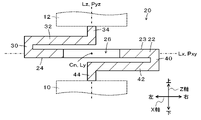
図1は、本発明の一実施例としての弾性支持構造20の外観斜視図であり、図2は、弾性支持構造20の断面図である。図1において、左右方向がX軸方向であり、前後方向がY軸方向(弾性支持構造20の幅方向)であり、上下方向がZ軸方向(弾性支持構造20の高さ方向)である。また、図1や図2において、弾性支持構造20のX軸、Y軸、Z軸方向における中心Cnを通ってX軸、Y軸、Z軸方向に延びる直線をそれぞれ軸線Lx,Ly,Lzといい、中心Cnを通るXY平面、XZ平面、YZ平面をそれぞれ所定XY平面Pxy、所定XZ平面Pxz、所定YZ平面Pyzという。したがって、図2は、図1の弾性支持構造20の所定XZ平面Pxzにおける断面図となる。なお、弾性支持構造20の配置は、図1の向きに限定されるものではない。
1 is an external perspective view of an elastic support structure 20 as one embodiment of the present invention, and FIG. 2 is a cross-sectional view of the elastic support structure 20. FIG. In FIG. 1, the horizontal direction is the X-axis direction, the front-rear direction is the Y-axis direction (the width direction of the elastic support structure 20), and the vertical direction is the Z-axis direction (the height direction of the elastic support structure 20). 1 and 2, the straight lines extending in the X-, Y-, and Z-axis directions through the center Cn in the X-, Y-, and Z-axis directions of the elastic support structure 20 are referred to as axis lines Lx, Ly, and Lz, respectively. The XY plane, XZ plane, and YZ plane passing through the center Cn are called a predetermined XY plane Pxy, a predetermined XZ plane Pxz, and a predetermined YZ plane Pyz, respectively. Therefore, FIG. 2 is a cross-sectional view of the elastic support structure 20 of FIG. 1 taken along the predetermined XZ plane Pxz. Note that the arrangement of the elastic support structure 20 is not limited to the orientation shown in FIG.
実施例の弾性支持構造20は、例えば、樹脂材料の射出成形、ブロー成形、押出し成形、3D印刷や、金属材料の鋳造、鍛造、プレス、切削、3D印刷などにより一体成形されている。この弾性支持構造20は、図2に示すように、Z軸方向におけるベース部材10とマウント部材12との間に配置され、ベース部材10により支持されると共にマウント部材12を支持する。
The elastic support structure 20 of the embodiment is integrally molded, for example, by injection molding, blow molding, extrusion molding, or 3D printing of resin materials, or casting, forging, pressing, cutting, or 3D printing of metal materials. The elastic support structure 20 is arranged between the base member 10 and the mount member 12 in the Z-axis direction, and supported by the base member 10 and the mount member 12, as shown in FIG.
弾性支持構造20は、図1や図2に示すように、平板部22と、第1繋ぎ部30と、第1梁部32と、第1軸部34と、第2繋ぎ部40と、第2梁部42と、第2軸部44とを備える。この弾性支持構造20は、所定XZ平面Pxz(軸線Lx,Lzを含む平面)に対して鏡像となるように形成されており、軸線Lzは、第1軸部34、第1梁部32の先端部、平板部22の中央部(後述の貫通孔26)、第2梁部42の先端部、第2軸部44を通っている。また、弾性支持構造20は、軸線Lyに対して回転対称(2回対称)となるように(所定XZ平面において中心Cnに対して点対称となるように)、具体的には、第1繋ぎ部30と第2繋ぎ部40、第1梁部32と第2梁部42、第1軸部34と第2軸部44がそれぞれ回転対称となるように形成されている。
As shown in FIGS. 1 and 2, the elastic support structure 20 includes a flat plate portion 22, a first connecting portion 30, a first beam portion 32, a first shaft portion 34, a second connecting portion 40, and a second connecting portion 40. It has two beam portions 42 and a second shaft portion 44 . The elastic support structure 20 is formed so as to be a mirror image of a predetermined XZ plane Pxz (a plane including the axes Lx and Lz), and the axis Lz is the tip of the first shaft portion 34 and the first beam portion 32. , the central portion of the flat plate portion 22 (a through hole 26 to be described later), the tip portion of the second beam portion 42 , and the second shaft portion 44 . In addition, the elastic support structure 20 is rotationally symmetrical (two-fold symmetrical) with respect to the axis Ly (point-symmetrically with respect to the center Cn in the predetermined XZ plane), specifically, the first joint The portion 30 and the second connecting portion 40, the first beam portion 32 and the second beam portion 42, and the first shaft portion 34 and the second shaft portion 44 are formed to be rotationally symmetrical.
平板部22は、所定YZ平面Pyzに対して鏡像となるようにXY方向に延在する矩形板状に形成されている。この平板部22の中央部には、所定YZ平面Pyzに対して鏡像となるようにZ軸方向に貫通する矩形状の貫通孔26が形成されている。矩形状の貫通孔26の前側および後側の内壁面は、それぞれXZ平面に沿って且つ互いに対向するように延在しており、第1繋ぎ部30側(左側)および第2繋ぎ部40側(右側)の内壁面は、それぞれYZ平面に沿って且つ互いに対向するように延在している。
The flat plate portion 22 is formed in a rectangular plate shape extending in the XY directions so as to be a mirror image with respect to the predetermined YZ plane Pyz. A rectangular through-hole 26 penetrating in the Z-axis direction is formed in the central portion of the flat plate portion 22 so as to be a mirror image with respect to the predetermined YZ plane Pyz. Front and rear inner wall surfaces of the rectangular through-hole 26 extend along the XZ plane so as to face each other, and extend toward the first connecting portion 30 side (left side) and the second connecting portion 40 side. The (right) inner wall surfaces extend along the YZ plane and face each other.
第1繋ぎ部30は、平板部22の外周部のX軸方向における左端部(第1部)から、平板部22と幅(Y方向における長さ)が同一で、Z軸方向における上側に延出されている。第1梁部32は、第1繋ぎ部30の上端部から平板部22の上面23に対して間隔をおいて且つ平板部22に平行に、X軸方向における右端部側に向かって軸線Lz周辺まで延出されている。この第1梁部32は、基端部側(第1繋ぎ部30側)から先端部側に向かうにつれて幅が狭くなるように形成されており、先端部の幅は、平板部22の貫通孔26の幅よりも狭くなっている。第1軸部34は、第1梁部32の先端部からZ軸方向における上側に延出されており、マウント部材12に当接または固定される。
The first connecting portion 30 has the same width (length in the Y direction) as the flat plate portion 22 and extends upward in the Z-axis direction from the left end (first portion) of the outer peripheral portion of the flat plate portion 22 in the X-axis direction. is served. The first beam portion 32 extends from the upper end portion of the first connecting portion 30 to the upper surface 23 of the flat plate portion 22 and parallel to the flat plate portion 22, and extends around the axis Lz toward the right end side in the X-axis direction. has been extended to The first beam portion 32 is formed so that the width of the first beam portion 32 decreases from the base end portion side (first connecting portion 30 side) toward the tip portion side. It is narrower than the width of 26. The first shaft portion 34 extends upward in the Z-axis direction from the distal end portion of the first beam portion 32 and abuts or is fixed to the mount member 12 .
第2繋ぎ部40は、平板部22の外周部のX軸方向における右端部(第2部)から、平板部22と幅(Y方向における長さ)が同一で、Z軸方向における下側に延出されている。第2梁部42は、第2繋ぎ部40の下端部から平板部22の下面24に対して間隔をおいて且つ平板部22に平行に、X軸方向における左端部側に向かって軸線Lz周辺まで延出されている。この第2梁部42は、基端部側(第2繋ぎ部40側)から先端部側に向かうにつれて幅が狭くなるように形成されており、先端部の幅は、平板部22の貫通孔26の幅よりも狭くなっている。なお、貫通孔26や第1梁部32の先端部、第2梁部42の先端部の幅は、平板部22や第1梁部32,第2梁部42の剛性などを考慮して設計される。第2軸部44は、第2梁部42の先端部からZ軸方向における下側に延出されており、ベース部材10に当接または固定される。
The second connecting portion 40 has the same width (length in the Y direction) as the flat plate portion 22 and extends downward in the Z-axis direction from the right end (second portion) of the outer peripheral portion of the flat plate portion 22 in the X-axis direction. has been deferred. The second beam portion 42 extends from the lower end portion of the second connecting portion 40 to the lower surface 24 of the flat plate portion 22 and is parallel to the flat plate portion 22 and extends around the axis Lz toward the left end side in the X-axis direction. has been extended to The second beam portion 42 is formed so that the width of the second beam portion 42 becomes narrower from the base end portion side (the second connecting portion 40 side) toward the tip portion side. It is narrower than the width of 26. The width of the through hole 26, the tip of the first beam portion 32, and the tip portion of the second beam portion 42 are designed in consideration of the rigidity of the flat plate portion 22, the first beam portion 32, and the second beam portion 42. be done. The second shaft portion 44 extends downward in the Z-axis direction from the distal end portion of the second beam portion 42 and abuts or is fixed to the base member 10 .
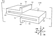
次に、こうして構成された弾性支持構造20の動作について説明する。図3は、比較例の弾性支持構造20Bの外観斜視図であり、図4は、比較例の弾性支持構造20Bの断面図である。図3および図4は、図1および図2にそれぞれ対応する。比較例の弾性支持構造20Bは、貫通孔26を有しない点や、平板部22と第1繋ぎ部30と第1梁部32と第1軸部34と第2繋ぎ部40と第2梁部42と第2軸部44との幅(Y軸方向における長さ)が同一に形成される点で、実施例の弾性支持構造20とは異なる。実施例の弾性支持構造20と比較例の弾性支持構造20Bとでは、こうした相違により、剛性特性が異なる。このため、弾性支持構造20について、弾性支持構造20Bと同様の剛性を補償するために、各部の厚みなどが調整されるものとした。
Next, the operation of the elastic support structure 20 configured in this manner will be described. FIG. 3 is an external perspective view of an elastic support structure 20B of a comparative example, and FIG. 4 is a cross-sectional view of the elastic support structure 20B of a comparative example. 3 and 4 correspond to FIGS. 1 and 2, respectively. The elastic support structure 20B of the comparative example does not have the through hole 26, and has the flat plate portion 22, the first connecting portion 30, the first beam portion 32, the first shaft portion 34, the second connecting portion 40 and the second beam portion. 42 and the second shaft portion 44 are formed to have the same width (length in the Y-axis direction), which is different from the elastic support structure 20 of the embodiment. Due to this difference, the elastic support structure 20 of the example and the elastic support structure 20B of the comparative example have different rigidity characteristics. Therefore, the thickness of each part of the elastic support structure 20 is adjusted in order to compensate for the same rigidity as that of the elastic support structure 20B.
図5は、実施例および比較例の弾性支持構造20,20Bの第1梁部32および第2梁部42が互いに接近するときの様子の一例を示す説明図である。図中、実線は、実施例の弾性支持構造20の様子を示し、破線は、比較例の弾性支持構造20Bの様子を示す。なお、図5では、見易さを考慮して、ハッチングを省略した。
FIG. 5 is an explanatory diagram showing an example of how the first beam portions 32 and the second beam portions 42 of the elastic support structures 20 and 20B of the embodiment and the comparative example approach each other. In the figure, the solid line indicates the elastic support structure 20 of the example, and the dashed line indicates the elastic support structure 20B of the comparative example. Note that hatching is omitted in FIG. 5 for ease of viewing.
比較例の弾性支持構造20Bでは、ベース部材10および/またはマウント部材12からの圧縮方向の外力により第1梁部32の先端部と第2梁部42との先端部とが互いに接近するときに、図中破線に示すように、第1梁部32の先端部が平板部22の上面23に当接すると共に第2梁部42の先端部が平板部22の下面24に当接するまで、平板部22や第1梁部32、第2梁部42の撓みを伴って両者が互いに接近することができる。そして、第1梁部32の先端部が平板部22の上面23に当接すると共に第2梁部42の先端部が平板部22の下面24に当接すると、全体として剛体と同様になり、振動吸収機能が低下する。これに対して、実施例の弾性支持構造20では、第1梁部32の先端部と第2梁部42との先端部とが互いに接近するときに、共に貫通孔26に進入することができるから、平板部22や第1梁部32、第2梁部42の撓みを伴って両者が互いにより接近することができる、即ち、初期状態からの両者の許容接近量を拡大することができる。なお、実施例の弾性支持構造20において、貫通孔26のX軸方向における長さが比較的短い場合には、第1梁部32の下面が貫通孔26の上面23側の縁部に当接すると共に第2梁部42の上面が貫通孔26の下面24側の縁部に当接するまで、第1梁部32の先端部と第2梁部42との先端部とが接近することができる。また、貫通孔26のX軸方向における長さが比較的長い場合には、第1梁部32の先端部と第2梁部42の先端部とが互いに当接するまで、第1梁部32の先端部と第2梁部42との先端部とが接近することができる。後者の場合に、前者の場合に比して、初期状態からの第1梁部32の先端部と第2梁部42の先端部との許容接近量をより拡大することができる。
In the elastic support structure 20B of the comparative example, when the tip of the first beam portion 32 and the tip of the second beam portion 42 approach each other due to an external force in the compression direction from the base member 10 and/or the mount member 12, , until the tip of the first beam portion 32 abuts the upper surface 23 of the flat plate portion 22 and the tip of the second beam portion 42 abuts the bottom surface 24 of the flat plate portion 22, as indicated by the broken line in the drawing. 22, the first beam portion 32, and the second beam portion 42 can be brought closer together. Then, when the tip of the first beam portion 32 contacts the upper surface 23 of the flat plate portion 22 and the tip of the second beam portion 42 contacts the lower surface 24 of the flat plate portion 22, the entire body becomes similar to a rigid body and vibrates. Absorptive function is reduced. In contrast, in the elastic support structure 20 of the embodiment, when the tip of the first beam portion 32 and the tip of the second beam portion 42 approach each other, both can enter the through hole 26 . Therefore, the flat plate portion 22, the first beam portion 32, and the second beam portion 42 can be brought closer to each other as the flat plate portion 22, the first beam portion 32, and the second beam portion 42 are bent. In the elastic support structure 20 of the embodiment, when the length of the through-hole 26 in the X-axis direction is relatively short, the lower surface of the first beam portion 32 abuts the edge of the through-hole 26 on the upper surface 23 side. At the same time, the tip of the first beam 32 and the tip of the second beam 42 can approach each other until the upper surface of the second beam 42 abuts the edge of the through hole 26 on the lower surface 24 side. Further, when the length of the through-hole 26 in the X-axis direction is relatively long, the first beam portion 32 and the second beam portion 42 may be separated from each other until the tip portion of the first beam portion 32 and the tip portion of the second beam portion 42 are in contact with each other. The tip portion and the tip portion of the second beam portion 42 can approach each other. In the latter case, compared with the former case, the allowable amount of approach between the tip of the first beam portion 32 and the tip of the second beam portion 42 from the initial state can be increased.
また、実施例の弾性支持構造20は、所定XZ平面Pxzに対して鏡像となるように形成されていると共に、軸線Lyに対して回転対称(2回対称)となるように、具体的には、第1繋ぎ部30と第2繋ぎ部40、第1梁部32と第2梁部42、第1軸部34と第2軸部44がそれぞれ回転対称となるように形成されている。これにより、ベース部材10および/またはマウント部材12からの圧縮方向の外力により第1梁部32の先端部と第2梁部42との先端部とが互いに接近するときや、その後に弾性力により互いに離間するときに、平板部22にX軸方向やY軸方向、Z軸方向における不均一な力が作用するのを抑制することができる。
Further, the elastic support structure 20 of the embodiment is formed so as to be a mirror image with respect to the predetermined XZ plane Pxz, and is rotationally symmetrical (two-fold symmetrical) with respect to the axis Ly. , the first connecting portion 30 and the second connecting portion 40, the first beam portion 32 and the second beam portion 42, and the first shaft portion 34 and the second shaft portion 44 are formed to be rotationally symmetrical. As a result, when the tip of the first beam portion 32 and the tip of the second beam portion 42 approach each other due to an external force in the compression direction from the base member 10 and/or the mount member 12, or after that due to the elastic force, When the plate portions 22 are separated from each other, it is possible to suppress uneven forces acting on the flat plate portions 22 in the X-axis direction, the Y-axis direction, and the Z-axis direction.
以上説明した実施例の弾性支持構造20では、平板部22は、その中央部にZ軸方向に貫通する貫通孔26を有する。これにより、平板部22が貫通孔26を有しないものに比して、自然状態からの第1梁部32の先端部と第2梁部42の先端部との許容接近量を拡大することができる。
In the elastic support structure 20 of the embodiment described above, the flat plate portion 22 has a through hole 26 penetrating in the Z-axis direction at its central portion. As a result, the allowable amount of approach between the tip end of the first beam portion 32 and the tip end portion of the second beam portion 42 from the natural state can be increased compared to when the flat plate portion 22 does not have the through hole 26. can.
実施例の弾性支持構造20では、平板部22は、矩形板状に形成されるものとした。しかし、これに限定されるものではなく、例えば、平板部22は、円板状や、楕円板状などに形成制されるものとしてもよい。
In the elastic support structure 20 of the embodiment, the flat plate portion 22 is formed in a rectangular plate shape. However, the shape is not limited to this, and for example, the flat plate portion 22 may be formed in a disk shape, an elliptical plate shape, or the like.
実施例の弾性支持構造20では、図1や図2に示したように、平板部22の矩形状の貫通孔26の第1繋ぎ部30側(左側)および第2繋ぎ部40側(右側)の内壁面は、それぞれYZ平面に沿って且つ互いに対向するように延在するものとした。しかし、図6の変形例の弾性支持構造120に示すように、平板部22は、貫通孔26に代えて、貫通孔126を有するものとしてもよい。貫通孔126の第1繋ぎ部30側、第2繋ぎ部40側の内壁面126a,126bは、所定XY平面側から平板部22の上面23(第1面)側に向かうにつれてそれぞれX軸方向における第1繋ぎ部30側、第2繋ぎ部40側に接近するように傾斜する一対の上側傾斜面127a,127bと、所定XY平面側から平板部22の下面24(第2面)側に向かうにつれてそれぞれX軸方向における第1繋ぎ部30側、第2繋ぎ部40側に接近するように傾斜する一対の下側傾斜面128a,128bとを有する。こうすれば、第1梁部32の先端部と第2梁部42との先端部とが互いに接近するときに、第1梁部32の下面が貫通孔126の上面23側の縁部に当接するのを抑制することができると共に第2梁部42の上面が貫通孔126の下面24側の縁部に当接するのを抑制することができる。なお、この効果を奏するためには、貫通孔126の第1繋ぎ部30側の内壁面126aが上側傾斜面127aを有すると共に第2繋ぎ部側の内壁面126bが下側傾斜面128bを有するものであればよく、内壁面126aが下側傾斜面128aを有しないものとしてもよいし、内壁面126bが上側傾斜面127bを有しないものとしてもよい。
In the elastic support structure 20 of the embodiment, as shown in FIGS. 1 and 2 , the rectangular through-hole 26 of the flat plate portion 22 is positioned on the first connecting portion 30 side (left side) and on the second connecting portion 40 side (right side). The inner wall surfaces of each extend along the YZ plane and face each other. However, as shown in the modified elastic support structure 120 of FIG. The inner wall surfaces 126a and 126b of the through-hole 126 on the first connecting portion 30 side and the second connecting portion 40 side extend in the X-axis direction from the predetermined XY plane side toward the upper surface 23 (first surface) of the flat plate portion 22. A pair of upper inclined surfaces 127a and 127b inclined so as to approach the first connecting portion 30 side and the second connecting portion 40 side, and from the predetermined XY plane side toward the lower surface 24 (second surface) side of the flat plate portion 22 It has a pair of lower inclined surfaces 128a and 128b inclined so as to approach the first connecting portion 30 side and the second connecting portion 40 side in the X-axis direction, respectively. In this way, when the tip of the first beam 32 and the tip of the second beam 42 approach each other, the lower surface of the first beam 32 contacts the edge of the through hole 126 on the upper surface 23 side. Contact can be suppressed, and contact of the upper surface of the second beam portion 42 with the edge portion of the through hole 126 on the lower surface 24 side can be suppressed. In order to achieve this effect, the inner wall surface 126a of the through hole 126 on the side of the first connecting portion 30 should have an upper inclined surface 127a, and the inner wall surface 126b of the through hole 126 on the side of the second connecting portion should have a lower inclined surface 128b. The inner wall surface 126a may not have the lower inclined surface 128a, and the inner wall surface 126b may not have the upper inclined surface 127b.
実施例の弾性支持構造20では、図1や図2に示したように、平板部22は、貫通孔26を有するものとした。しかし、図7の変形例の弾性支持構造220に示すように、平板部22は、貫通孔26に代えて、第1凹部227および第2凹部228を有するものとしてもよい。弾性支持構造220において、第1凹部227は、平板部22の上面23から下面24側に窪んで形成され、第2凹部228は、所定XY平面Pxyに対して第1凹部227と鏡像となるように平板部22の下面24から上面23側に窪んで形成されている。第1凹部227および第2凹部228は、それぞれ、XY平面に沿って延在する矩形状の底面と、底面の前側および後側でそれぞれXZ平面に沿って延在する一対の(互いに対向する)内壁面と、底面の第1繋ぎ部30側(左側)および第2繋ぎ部40側(右側)でそれぞれYZ平面に沿って延在する一対の(互いに対向する)内壁面とを有する。なお、実施例の弾性支持構造20の貫通孔26は、弾性支持構造220の第1凹部227と第2凹部228とのZ軸方向における連通により形成されたものとして考えることができる。
In the elastic support structure 20 of the embodiment, the flat plate portion 22 has a through hole 26 as shown in FIGS. However, as shown in the modified elastic support structure 220 of FIG. In the elastic support structure 220, the first concave portion 227 is recessed from the upper surface 23 of the flat plate portion 22 toward the lower surface 24 side, and the second concave portion 228 is formed so as to be a mirror image of the first concave portion 227 with respect to the predetermined XY plane Pxy. It is recessed from the lower surface 24 of the flat plate portion 22 to the upper surface 23 side. Each of the first concave portion 227 and the second concave portion 228 has a rectangular bottom surface extending along the XY plane, and a pair of (opposite to each other) extending along the XZ plane on the front and rear sides of the bottom surface. It has an inner wall surface and a pair of (mutually opposed) inner wall surfaces extending along the YZ plane on the first connecting portion 30 side (left side) and the second connecting portion 40 side (right side) of the bottom surface. Note that the through hole 26 of the elastic support structure 20 of the embodiment can be considered as being formed by communication between the first concave portion 227 and the second concave portion 228 of the elastic support structure 220 in the Z-axis direction.
図7の弾性支持構造220では、平板部22は、第1凹部227および第2凹部228を有するものとした。しかし、図8の変形例の弾性支持構造320に示すように、平板部22は、第1凹部227および第2凹部228に代えて、第1凹部327および第2凹部328を有するものとしてもよい。第1凹部327は、底面を有さずに、互いに連続すると共に所定XY平面側から平板部22の上面23側に向かうにつれてX軸方向における第1繋ぎ部30側,第2繋ぎ部40側に接近するように傾斜する一対の上側傾斜面327a,327bと、上側傾斜面327a,327bの前側および後側でYZ平面に沿って延在し且つ互いに対向する一対の内壁面とを有する。また、第2凹部328は、底面を有さずに、互いに連続すると共に所定XY平面側から平板部22の下面24側に向かうにつれてX軸方向における第1繋ぎ部30側,第2繋ぎ部40側に接近するように傾斜する一対の下側傾斜面328a,328bと、下側傾斜面328a,328bの前側および後側でYZ平面に沿って延在し且つ互いに対向する一対の内壁面とを有する。こうすれば、第1梁部32の先端部と第2梁部42との先端部とが互いに接近するときに、第1梁部32の下面が第1凹部327の上面23側の縁部に当接するのを抑制することができると共に第2梁部42の上面が第2凹部328の下面24側の縁部に当接するのを抑制することができる。なお、第1凹部327および第2凹部328は、それぞれXY平面に沿って延在する底面を有するものとしてもよい。
In the elastic support structure 220 of FIG. 7, the flat plate portion 22 has the first concave portion 227 and the second concave portion 228 . However, as shown in the modified elastic support structure 320 of FIG. 8, the flat plate portion 22 may have a first recess 327 and a second recess 328 instead of the first recess 227 and the second recess 228. . The first concave portions 327 do not have a bottom surface, and are continuous with each other, and extend toward the first connecting portion 30 side and the second connecting portion 40 side in the X-axis direction from the predetermined XY plane side toward the upper surface 23 side of the flat plate portion 22 . It has a pair of upper inclined surfaces 327a, 327b that are inclined to approach each other, and a pair of inner wall surfaces that extend along the YZ plane and face each other on the front and rear sides of the upper inclined surfaces 327a, 327b. The second concave portions 328 do not have a bottom surface and are continuous with each other, and extend toward the first connecting portion 30 side and the second connecting portion 40 side in the X-axis direction from the predetermined XY plane side toward the lower surface 24 side of the flat plate portion 22 . A pair of lower inclined surfaces 328a, 328b inclined so as to approach each other and a pair of inner wall surfaces facing each other and extending along the YZ plane on the front and rear sides of the lower inclined surfaces 328a, 328b. have. In this way, when the tip of the first beam portion 32 and the tip of the second beam portion 42 approach each other, the lower surface of the first beam portion 32 touches the edge of the first recess 327 on the upper surface 23 side. Abutment can be suppressed, and the upper surface of the second beam portion 42 can be suppressed from abutting the edge of the second recess 328 on the lower surface 24 side. The first recess 327 and the second recess 328 may each have a bottom surface extending along the XY plane.
実施例の弾性支持構造20では、第1繋ぎ部30は、平板部22の外周部からZ軸方向における上側に延出されて第1梁部32に繋がるものとした。しかし、これに限定されるものではなく、例えば、第1繋ぎ部30は、平板部22の外周部から軸線Lzから離間する側に凸となるように湾曲しながらZ軸方向における上側に延出されて第1梁部32に繋がるものとしてもよい。第2繋ぎ部40についても同様に考えることができる。
In the elastic support structure 20 of the embodiment, the first connecting portion 30 extends upward in the Z-axis direction from the outer peripheral portion of the flat plate portion 22 and connects to the first beam portion 32 . However, the present invention is not limited to this. For example, the first connecting portion 30 extends upward in the Z-axis direction while curving from the outer peripheral portion of the flat plate portion 22 to the side away from the axis Lz. It is good also as what is connected with the 1st beam part 32 by being connected. The second connecting portion 40 can also be considered in the same way.
実施例の弾性支持構造20では、第1繋ぎ部30は、平板部22と幅(Y方向における長さ)が同一に形成され、第1梁部32は、基端部側から先端部側に向かうにつれて幅が狭くなるように形成されるものとした。しかし、第1繋ぎ部30および第1梁部32は、第1繋ぎ部30の平板部22との付け根部から第1梁部32の先端部に向かうにつれて幅が狭くなるように形成されるものとしてもよい。第2繋ぎ部40および第2梁部42についても同様に考えることができる。また、第1梁部32は、基端部から先端部まで、貫通孔26よりも狭い略一定幅で延びるように形成されるものとしてもよい。第2梁部42についても同様に考えることができる。さらに、図9の変形例の弾性支持構造420に示すように、平板部22と第1繋ぎ部30と第1梁部32と第1軸部34と第2繋ぎ部40と第2梁部42と第2軸部44との幅(Y軸方向における長さ)が同一に形成されるものとしてもよい。この場合、平板部22に、弾性支持構造20の貫通孔26に相当するものを形成することができないため、上面23から下面24側に窪むと共にY軸方向における全体に亘って延在する第1凹部427と、下面24から上面23側に窪むと共にY軸方向における全体に亘って延在する第2凹部428とを形成することが考えられる。この弾性支持構造420は、図3および図4の比較例の弾性支持構造20Bに第1凹部427および第2凹部428を形成したものとして考えることができる。
In the elastic support structure 20 of the embodiment, the first connecting portion 30 is formed to have the same width (length in the Y direction) as the flat plate portion 22, and the first beam portion 32 extends from the base end side to the tip end side. It is formed so that the width becomes narrower as it goes. However, the first connecting portion 30 and the first beam portion 32 are formed so that the width becomes narrower from the root portion of the first connecting portion 30 to the flat plate portion 22 toward the tip portion of the first beam portion 32. may be The second connecting portion 40 and the second beam portion 42 can be similarly considered. Also, the first beam portion 32 may be formed to extend from the base end portion to the tip end portion with a substantially constant width that is narrower than the through hole 26 . The second beam portion 42 can be similarly considered. Furthermore, as shown in the elastic support structure 420 of the modified example in FIG. and the second shaft portion 44 may have the same width (length in the Y-axis direction). In this case, since it is not possible to form the through hole 26 of the elastic support structure 20 in the flat plate portion 22 , the second hole recesses from the upper surface 23 toward the lower surface 24 and extends entirely in the Y-axis direction. It is conceivable to form a first recess 427 and a second recess 428 recessed from the lower surface 24 toward the upper surface 23 and extending over the entire Y-axis direction. This elastic support structure 420 can be considered as a first recess 427 and a second recess 428 formed in the elastic support structure 20B of the comparative example of FIGS.
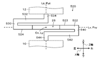
実施例の弾性支持構造20では、図1や図2に示したように、平板部22は、その中央部に貫通孔26を有し、第1梁部32および第2梁部42は、基端部側(第1繋ぎ部30側)から先端部側に向かうにつれて幅(Y軸方向における長さ)が狭くなるように形成されるものとした。しかし、図10や図11の変形例の弾性支持構造520に示すように、弾性支持構造20の平板部22と第1梁部32と第1軸部34と第2梁部42と第2軸部44とに代えて、平板部522と一対の第1梁部532と一対の第1軸部534と一対の第2梁部542と一対の第2軸部544とを備えるものとしてもよい。図10は、弾性支持構造520の外観斜視図であり、図11は、弾性支持構造520の後面図である。一対の第1梁部532は、第1繋ぎ部530のY軸方向における両端部から平板部522に平行に、X軸方向における右端部側に向かって延出されている。一対の第2梁部542は、第2繋ぎ部540のY軸方向における両端部から平板部522に平行に、X軸方向における左端部側に向かって延出されている。平板部522には、弾性支持構造20の平板部22と同様の矩形板状に対してX軸方向における中央部で前側および後側から切り欠かれた一対の切欠部526が形成されている。一対の第1梁部532のY軸方向における間隔、および、一対の第2梁部542のY軸方向における間隔は、平板部522のX軸方向における中央部の幅よりも若干広く設計されている。この弾性支持構造520では、一対の第1梁部532の先端部と一対の第2梁部542との先端部とが互いに接近するときに、それぞれ対応する切欠部526に進入することができるから、図3および図4の比較例の弾性支持構造20Bに比して、平板部522や一対の第1梁部532、一対の第2梁部542の撓みを伴って両者が互いにより接近することができる、即ち、初期状態からの両者の許容接近量を拡大することができる。なお、一対の切欠部526の第1繋ぎ部30側、第2繋ぎ部40側の内壁面は、上述の弾性支持構造120の貫通孔126の第1繋ぎ部30側、第2繋ぎ部40側の内壁面126a,126b(図6参照)と同様に形成されるものとしてもよい。また、各切欠部526は、弾性支持構造220の第1凹部227および第2凹部228(図7参照)や、弾性支持構造320の第1凹部327および第2凹部328と同様に形成されるものとしてもよい。
In the elastic support structure 20 of the embodiment, as shown in FIGS. 1 and 2, the flat plate portion 22 has a through-hole 26 in its central portion, and the first beam portion 32 and the second beam portion 42 are provided at the base. The width (the length in the Y-axis direction) is formed so as to narrow from the end portion side (first connecting portion 30 side) toward the tip portion side. However, as shown in the elastic support structure 520 of the modified example of FIGS. Instead of the portion 44 , a plate portion 522 , a pair of first beam portions 532 , a pair of first shaft portions 534 , a pair of second beam portions 542 and a pair of second shaft portions 544 may be provided. 10 is an external perspective view of the elastic support structure 520, and FIG. 11 is a rear view of the elastic support structure 520. FIG. The pair of first beam portions 532 extends from both ends of the first connecting portion 530 in the Y-axis direction toward the right end portion in the X-axis direction in parallel with the flat plate portion 522 . The pair of second beam portions 542 extends from both ends of the second connecting portion 540 in the Y-axis direction toward the left end portion in the X-axis direction in parallel with the flat plate portion 522 . The flat plate portion 522 is formed with a pair of notch portions 526 cut from the front side and the rear side at the central portion in the X-axis direction of a rectangular plate shape similar to the flat plate portion 22 of the elastic support structure 20 . The distance between the pair of first beam portions 532 in the Y-axis direction and the distance between the pair of second beam portions 542 in the Y-axis direction are designed to be slightly wider than the width of the central portion of the flat plate portion 522 in the X-axis direction. there is In this elastic support structure 520, when the tips of the pair of first beams 532 and the tips of the pair of second beams 542 approach each other, they can enter the corresponding notches 526. 3 and 4, the flat plate portion 522, the pair of first beam portions 532, and the pair of second beam portions 542 are brought closer to each other as they flex. That is, it is possible to expand the allowable approach amount of both from the initial state. In addition, the inner wall surfaces of the pair of notch portions 526 on the first connecting portion 30 side and the second connecting portion 40 side correspond to the first connecting portion 30 side and the second connecting portion 40 side of the through hole 126 of the elastic support structure 120 described above. may be formed in the same manner as the inner wall surfaces 126a, 126b (see FIG. 6). Each notch 526 is formed in the same manner as the first recess 227 and the second recess 228 (see FIG. 7) of the elastic support structure 220 and the first recess 327 and the second recess 328 of the elastic support structure 320. may be
実施例の弾性支持構造20では、平板部22と第1梁部32と第2梁部42とは、互いに平行であるものとした。しかし、これに限定されるものではなく、例えば、第1梁部32および第2梁部42は、それぞれ基端部側から先端部側に向かうにつれて平板部22から離間するように延出されるものとしてもよい。
In the elastic support structure 20 of the embodiment, the flat plate portion 22, the first beam portion 32 and the second beam portion 42 are parallel to each other. However, the invention is not limited to this. For example, the first beam portion 32 and the second beam portion 42 extend away from the flat plate portion 22 as they go from the base end side to the tip end side. may be
実施例の弾性支持構造20では、所定XZ平面Pxzに対して鏡像となるように形成されていると共に、軸線Lyに対して回転対称(2回対称)となるように、具体的には、第1繋ぎ部30と第2繋ぎ部40、第1梁部32と第2梁部42、第1軸部34と第2軸部44がそれぞれ回転対称となるように形成されているものとした。しかし、所定XZ平面Pxzに対して鏡像とならないものとしてもよい。また、軸線Lyに対して回転対称とならない、例えば、軸線Lyに対して第1繋ぎ部30と第2繋ぎ部40とが回転対称とならないもの(例えば、厚みや幅などが互いに異なるものや、第1繋ぎ部30がZ軸方向に沿って延在するのに対して第2繋ぎ部40が軸線Lzから離間する側に凸となるように湾曲しながら延在するものなど)としてもよい。
The elastic support structure 20 of the embodiment is formed so as to be a mirror image with respect to the predetermined XZ plane Pxz, and is rotationally symmetrical (two-fold symmetrical) with respect to the axis Ly. The first connecting portion 30 and the second connecting portion 40, the first beam portion 32 and the second beam portion 42, and the first shaft portion 34 and the second shaft portion 44 are formed to be rotationally symmetrical. However, it may not be a mirror image with respect to the predetermined XZ plane Pxz. In addition, the first connecting portion 30 and the second connecting portion 40 are not rotationally symmetrical with respect to the axis Ly, for example, are not rotationally symmetrical with respect to the axis Ly (for example, different thicknesses and widths, While the first connecting portion 30 extends along the Z-axis direction, the second connecting portion 40 may extend while curving so as to be convex toward the side away from the axis Lz).
実施例の弾性支持構造20では、第1軸部34がマウント部材12に当接または固定されると共に、第2軸部44がベース部材10に当接または固定されるものとした。しかし、第1軸部34および第2軸部44を有さずに、第1梁部32の先端部がマウント部材12に当接または固定されると共に、第2梁部42の先端部がベース部材10に当接または固定されるものとしてもよい。
In the elastic support structure 20 of the embodiment, the first shaft portion 34 abuts or is fixed to the mount member 12 and the second shaft portion 44 is abutted or fixed to the base member 10 . However, without having the first shaft portion 34 and the second shaft portion 44, the tip portion of the first beam portion 32 abuts or is fixed to the mount member 12, and the tip portion of the second beam portion 42 is attached to the base. It may be abutted or fixed to the member 10 .
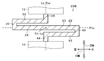
実施例の弾性支持構造20では、平板部22と第1繋ぎ部30と第1梁部32と第1軸部34と第2繋ぎ部40と第2梁部42と第2軸部44とを備えるものとした。しかし、図12や図13の変形例の弾性支持構造620に示すように、それぞれが弾性支持構造20と同様に形成された複数の弾性要素630が軸線Lz方向に沿って直列に繋がって構成されるものとしてもよい。図12は、弾性支持構造620の外観斜視図であり、図13は、弾性支持構造620の断面図である。図12および図13は、図1および図2にそれぞれ対応する。この弾性支持構造620でも、実施例の弾性支持構造20と同様の効果を奏することができる。具体的には、ベース部材10および/またはマウント部材12からの圧縮方向の外力により、弾性支持構造620の各弾性要素630の第1梁部32の先端部と第2梁部42との先端部とが互いに接近するときに、何れも貫通孔26に進入することができるから、各弾性要素630が貫通孔26を有しないものに比して、両者が互いにより接近することができる、即ち、初期状態からの両者の許容接近量を拡大することができる。
In the elastic support structure 20 of the embodiment, the flat plate portion 22, the first connecting portion 30, the first beam portion 32, the first shaft portion 34, the second connecting portion 40, the second beam portion 42, and the second shaft portion 44 are I was prepared. However, as shown in the modified elastic support structure 620 of FIGS. 12 and 13, a plurality of elastic elements 630 formed in the same manner as the elastic support structure 20 are connected in series along the axis Lz direction. It may be 12 is an external perspective view of the elastic support structure 620, and FIG. 13 is a cross-sectional view of the elastic support structure 620. FIG. 12 and 13 correspond to FIGS. 1 and 2, respectively. This elastic support structure 620 can also provide the same effects as the elastic support structure 20 of the embodiment. Specifically, the tip of the first beam portion 32 and the tip portion of the second beam portion 42 of each elastic element 630 of the elastic support structure 620 are compressed by the external force in the compression direction from the base member 10 and/or the mount member 12 . can enter the through-hole 26 when the elastic elements 630 approach each other, they can approach each other more than if each elastic element 630 does not have a through-hole 26, that is, It is possible to expand the allowable amount of approach between the two from the initial state.
弾性支持構造620では、それぞれが弾性支持構造20と同様に形成された複数の弾性要素630が軸線Lz方向に沿って直列に繋がって構成されるものとした。しかし、これに限定されるものではなく、例えば、複数の弾性要素630のうちの一部または全部が、弾性支持構造120,220,320,420,520などと同様に形成された弾性要素に置き換えられるものとしてもよいし、複数の弾性要素630のうちの一部が、貫通孔や第1凹部、第2凹部を有さない弾性要素に置き換えられるものとしてもよい。
In the elastic support structure 620, a plurality of elastic elements 630 each formed in the same manner as the elastic support structure 20 are connected in series along the direction of the axis Lz. However, it is not limited to this, and for example, some or all of the plurality of elastic elements 630 may be replaced with elastic elements formed similarly to the elastic support structures 120, 220, 320, 420, 520, etc. Alternatively, some of the plurality of elastic elements 630 may be replaced with elastic elements that do not have through holes, first recesses, or second recesses.
実施例の主要な要素と課題を解決するための手段の欄に記載した発明の主要な要素との対応関係について説明する。実施例では、平板部22が「平板部」に相当し、第1梁部32が「第1梁部」に相当し、第2梁部42が「第2梁部」に相当する。
The correspondence between the main elements of the embodiment and the main elements of the invention described in the column of Means for Solving the Problems will be explained. In the embodiment, the flat plate portion 22 corresponds to the "flat plate portion", the first beam portion 32 corresponds to the "first beam portion", and the second beam portion 42 corresponds to the "second beam portion".
なお、実施例の主要な要素と課題を解決するための手段の欄に記載した発明の主要な要素との対応関係は、実施例が課題を解決するための手段の欄に記載した発明を実施するための形態を具体的に説明するための一例であることから、課題を解決するための手段の欄に記載した発明の要素を限定するものではない。即ち、課題を解決するための手段の欄に記載した発明についての解釈はその欄の記載に基づいて行なわれるべきものであり、実施例は課題を解決するための手段の欄に記載した発明の具体的な一例に過ぎないものである。
Note that the correspondence relationship between the main elements of the examples and the main elements of the invention described in the column of Means for Solving the Problems is the Since it is an example for specifically explaining the mode for solving the problem, it does not limit the elements of the invention described in the column of the means for solving the problem. That is, the interpretation of the invention described in the column of Means to Solve the Problem should be made based on the description in that column, and the Examples are based on the description of the invention described in the column of Means to Solve the Problem. This is only a specific example.
以上、本発明を実施するための形態について実施例を用いて説明したが、本発明はこうした実施例に何等限定されるものではなく、本発明の要旨を逸脱しない範囲内において、種々なる形態で実施し得ることは勿論である。
Although the embodiments for carrying out the present invention have been described above, the present invention is not limited to such embodiments at all, and can be modified in various forms without departing from the scope of the present invention. Of course, it can be implemented.
Claims (9)
- 軸線に直交する方向に沿って延在する平板部と、
前記平板部の外周部の第1部に第1繋ぎ部を介して繋がると共に前記平板部の軸線方向における第1面に対して間隔をおいて前記軸線側に延出される第1梁部と、
前記平板部の前記外周部の前記軸線を挟んで前記第1部とは反対側の第2部に第2繋ぎ部を介して繋がると共に前記平板部の前記軸線方向における第2面に対して間隔をおいて前記軸線側に延出される第2梁部と、
を備える弾性支持構造であって、
前記平板部は、前記第1梁部が前記第2梁部に接近するときに前記第1梁部の少なくとも前記先端部が進入可能に前記第1面から窪む第1凹部を有すると共に前記第2梁部が前記第1梁部に接近するときに前記第2梁部の少なくとも前記先端部が進入可能に前記第2面から窪む第2凹部とを有する、
弾性支持構造。 a flat plate portion extending along a direction orthogonal to the axis;
a first beam portion connected to a first portion of the outer peripheral portion of the flat plate portion via a first connecting portion and extending toward the axial side with a gap from a first surface in the axial direction of the flat plate portion;
The outer peripheral portion of the flat plate portion is connected to the second portion on the opposite side of the first portion across the axis through a second connecting portion, and is spaced from the second surface of the flat plate portion in the axial direction. a second beam portion extending toward the axis with a
A resilient support structure comprising:
The flat plate portion has a first recess recessed from the first surface so that at least the tip portion of the first beam portion can enter when the first beam portion approaches the second beam portion, and the first recess portion is recessed from the first surface. a second recess that is recessed from the second surface so that at least the tip portion of the second beam can enter when the two beams approach the first beam;
Elastic support structure. - 請求項1記載の弾性支持構造であって、
前記第1凹部および前記第2凹部は、互いの連通により前記軸線方向に貫通する貫通孔を形成する、
弾性支持構造。 The elastic support structure of claim 1, comprising:
The first recess and the second recess form a through hole penetrating in the axial direction by mutual communication,
Elastic support structure. - 請求項1または2記載の弾性支持構造であって、
前記第1梁部の前記先端部の幅および前記第2梁部の前記先端部の幅は、前記平板部の幅よりも狭くなるように形成されている、
弾性支持構造。 The elastic support structure according to claim 1 or 2,
The width of the tip portion of the first beam portion and the width of the tip portion of the second beam portion are formed to be narrower than the width of the flat plate portion.
Elastic support structure. - 請求項3記載の弾性支持構造であって、
前記第1梁部は、前記第1繋ぎ部側から前記先端部側に向かうにつれて幅が狭くなるように形成されており、
前記第2梁部は、前記第2繋ぎ部側から前記先端部側に向かうにつれて幅が狭くなるように形成されている、
弾性支持構造。 The elastic support structure according to claim 3,
The first beam portion is formed so that the width becomes narrower from the first connecting portion side toward the tip portion side,
The second beam portion is formed so that the width becomes narrower from the second connecting portion side toward the tip portion side,
Elastic support structure. - 請求項1または2記載の弾性支持構造であって、
前記第1梁部は、前記第1繋ぎ部の幅方向に間隔をおいて前記軸線側に複数延出され、
前記第2梁部は、前記第2繋ぎ部の幅方向に間隔をおいて前記軸線側に複数延出され、
前記第1凹部は、前記複数の第1梁部の少なくとも前記先端部が進入可能に複数形成され、
前記第2凹部は、前記複数の第2梁部の少なくとも前記先端部が進入可能に複数形成されている、
弾性支持構造。 The elastic support structure according to claim 1 or 2,
a plurality of the first beam portions extending toward the axis line at intervals in the width direction of the first connecting portion;
a plurality of the second beam portions extending toward the axis line at intervals in the width direction of the second connecting portion;
A plurality of the first recesses are formed so that at least the tip portions of the plurality of first beam portions can enter,
A plurality of the second recesses are formed so that at least the tip portions of the plurality of second beam portions can enter,
Elastic support structure. - 請求項1ないし5のうちの何れか1つの請求項に記載の弾性支持構造であって、
前記第1凹部は、前記第2面側から前記第1面側に向かうにつれて前記第1繋ぎ部側に傾斜する第1傾斜面を有し、
前記第2凹部は、前記第1面側から前記第2面側に向かうにつれて前記第2繋ぎ部側に傾斜する第2傾斜面を有する、
弾性支持構造。 An elastic support structure according to any one of claims 1 to 5,
The first concave portion has a first inclined surface that inclines toward the first connecting portion side from the second surface side toward the first surface side,
The second concave portion has a second inclined surface that is inclined toward the second connecting portion side from the first surface side toward the second surface side,
Elastic support structure. - 請求項1ないし6のうちの何れか1つの請求項に記載の弾性支持構造であって、
前記平板部と前記第1梁部と前記第2梁部とは、互いに平行となるように形成されている、
弾性支持構造。 An elastic support structure according to any one of claims 1 to 6,
The flat plate portion, the first beam portion, and the second beam portion are formed so as to be parallel to each other,
Elastic support structure. - 請求項1ないし7のうちの何れか1つの請求項に記載の弾性支持構造であって、
前記第1梁部および前記第2梁部は、前記平板部内の所定点に対して互いに点対称となるように形成されており、
前記第1繋ぎ部および前記第2繋ぎ部は、前記所定点に対して互いに点対称となるように形成されている、
弾性支持構造。 An elastic support structure according to any one of claims 1 to 7,
The first beam portion and the second beam portion are formed so as to be point-symmetrical to each other with respect to a predetermined point within the flat plate portion,
The first connecting portion and the second connecting portion are formed so as to be symmetrical to each other with respect to the predetermined point.
Elastic support structure. - 請求項1ないし8のうちの何れか1つの請求項に記載の弾性支持構造であって、
前記平板部、前記第1梁部、前記第2梁部を有する複数の弾性要素が前記軸線方向に沿って直列に繋がって構成されている、
弾性支持構造。 An elastic support structure according to any one of claims 1 to 8,
A plurality of elastic elements having the flat plate portion, the first beam portion, and the second beam portion are connected in series along the axial direction,
Elastic support structure.
Priority Applications (2)
| Application Number | Priority Date | Filing Date | Title |
|---|---|---|---|
| JP2022529388A JP7154674B1 (en) | 2021-07-02 | 2021-07-02 | Elastic support structure |
| PCT/JP2021/025111 WO2023276139A1 (en) | 2021-07-02 | 2021-07-02 | Elastic support structure |
Applications Claiming Priority (1)
| Application Number | Priority Date | Filing Date | Title |
|---|---|---|---|
| PCT/JP2021/025111 WO2023276139A1 (en) | 2021-07-02 | 2021-07-02 | Elastic support structure |
Publications (1)
| Publication Number | Publication Date |
|---|---|
| WO2023276139A1 true WO2023276139A1 (en) | 2023-01-05 |
Family
ID=83658142
Family Applications (1)
| Application Number | Title | Priority Date | Filing Date |
|---|---|---|---|
| PCT/JP2021/025111 WO2023276139A1 (en) | 2021-07-02 | 2021-07-02 | Elastic support structure |
Country Status (2)
| Country | Link |
|---|---|
| JP (1) | JP7154674B1 (en) |
| WO (1) | WO2023276139A1 (en) |
Citations (6)
| Publication number | Priority date | Publication date | Assignee | Title |
|---|---|---|---|---|
| JPS4875039U (en) * | 1971-12-20 | 1973-09-18 | ||
| JPS4875040U (en) * | 1971-12-20 | 1973-09-18 | ||
| JPS5917341U (en) * | 1982-07-26 | 1984-02-02 | 松下電器産業株式会社 | elastic mechanism parts |
| JPH06103050B2 (en) * | 1986-08-11 | 1994-12-14 | 日本発条株式会社 | Leaf spring made of ceramic material |
| JPH07270670A (en) * | 1994-04-01 | 1995-10-20 | Fujitsu Denso Ltd | Fixing device for reflection mirror |
| JP2001514730A (en) * | 1997-03-13 | 2001-09-11 | ベーエムハー・クラオディウス・ペーターズ・アクチェンゲゼルシャフト | Mounting devices for moving parts of cooling or heating grids |
Family Cites Families (1)
| Publication number | Priority date | Publication date | Assignee | Title |
|---|---|---|---|---|
| DE102019109554A1 (en) * | 2019-04-11 | 2020-10-15 | Danto Invention Gmbh & Co. Kg | Spiral spring element made from a fiber plastic composite material |
-
2021
- 2021-07-02 JP JP2022529388A patent/JP7154674B1/en active Active
- 2021-07-02 WO PCT/JP2021/025111 patent/WO2023276139A1/en unknown
Patent Citations (6)
| Publication number | Priority date | Publication date | Assignee | Title |
|---|---|---|---|---|
| JPS4875039U (en) * | 1971-12-20 | 1973-09-18 | ||
| JPS4875040U (en) * | 1971-12-20 | 1973-09-18 | ||
| JPS5917341U (en) * | 1982-07-26 | 1984-02-02 | 松下電器産業株式会社 | elastic mechanism parts |
| JPH06103050B2 (en) * | 1986-08-11 | 1994-12-14 | 日本発条株式会社 | Leaf spring made of ceramic material |
| JPH07270670A (en) * | 1994-04-01 | 1995-10-20 | Fujitsu Denso Ltd | Fixing device for reflection mirror |
| JP2001514730A (en) * | 1997-03-13 | 2001-09-11 | ベーエムハー・クラオディウス・ペーターズ・アクチェンゲゼルシャフト | Mounting devices for moving parts of cooling or heating grids |
Also Published As
| Publication number | Publication date |
|---|---|
| JPWO2023276139A1 (en) | 2023-01-05 |
| JP7154674B1 (en) | 2022-10-18 |
Similar Documents
| Publication | Publication Date | Title |
|---|---|---|
| US5779412A (en) | Profile frame and connector | |
| JP3467712B2 (en) | Tool or workpiece mounting device | |
| JP5107283B2 (en) | clip | |
| WO2023276139A1 (en) | Elastic support structure | |
| JPH06862Y2 (en) | Spacer | |
| US20060151199A1 (en) | Wire binder | |
| US20110011998A1 (en) | Substrate holding/fixing structure | |
| JP2004301541A (en) | Elastic fixture and method for fixing length measuring device | |
| JP2020137238A (en) | Displacement expansion apparatus | |
| JP4857216B2 (en) | Dynamic damper | |
| JPH0882341A (en) | Vibration isolating mount | |
| JPH081230B2 (en) | Elastic support | |
| JP2020137239A (en) | Displacement expansion apparatus | |
| JP4368073B2 (en) | Self-propelled vehicle exhaust system suspension mounting apparatus and vehicle equipped with the apparatus | |
| KR102052298B1 (en) | Damping module with pinned connection theta damper | |
| CN1904395B (en) | Link device that is deformable in substantially one direction only | |
| JP2021060087A (en) | Plate material connecting mechanism | |
| CN112888866A (en) | Connecting member and frame | |
| US20210022246A1 (en) | Method for manufacturing flexible printed circuit terminal connection structures | |
| WO2024038889A1 (en) | Structure | |
| JP2002295587A (en) | Engine mount | |
| CN217308093U (en) | Substrate mounting structure | |
| JP2519184Y2 (en) | Mounting device for thin plate optical member | |
| WO2023007703A1 (en) | Structure | |
| US20210293264A1 (en) | Engagement structure |
Legal Events
| Date | Code | Title | Description |
|---|---|---|---|
| ENP | Entry into the national phase |
Ref document number: 2022529388 Country of ref document: JP Kind code of ref document: A |
|
| 121 | Ep: the epo has been informed by wipo that ep was designated in this application |
Ref document number: 21948443 Country of ref document: EP Kind code of ref document: A1 |
|
| NENP | Non-entry into the national phase |
Ref country code: DE |