WO2023238183A1 - 除湿機 - Google Patents
除湿機 Download PDFInfo
- Publication number
- WO2023238183A1 WO2023238183A1 PCT/JP2022/022765 JP2022022765W WO2023238183A1 WO 2023238183 A1 WO2023238183 A1 WO 2023238183A1 JP 2022022765 W JP2022022765 W JP 2022022765W WO 2023238183 A1 WO2023238183 A1 WO 2023238183A1
- Authority
- WO
- WIPO (PCT)
- Prior art keywords
- housing
- control box
- opening
- dehumidifier
- compressor
- Prior art date
- Legal status (The legal status is an assumption and is not a legal conclusion. Google has not performed a legal analysis and makes no representation as to the accuracy of the status listed.)
- Ceased
Links
Images


Classifications
-
- B—PERFORMING OPERATIONS; TRANSPORTING
- B01—PHYSICAL OR CHEMICAL PROCESSES OR APPARATUS IN GENERAL
- B01D—SEPARATION
- B01D53/00—Separation of gases or vapours; Recovering vapours of volatile solvents from gases; Chemical or biological purification of waste gases, e.g. engine exhaust gases, smoke, fumes, flue gases, aerosols
- B01D53/26—Drying gases or vapours
-
- F—MECHANICAL ENGINEERING; LIGHTING; HEATING; WEAPONS; BLASTING
- F24—HEATING; RANGES; VENTILATING
- F24F—AIR-CONDITIONING; AIR-HUMIDIFICATION; VENTILATION; USE OF AIR CURRENTS FOR SCREENING
- F24F2130/00—Control inputs relating to environmental factors not covered by group F24F2110/00
- F24F2130/20—Sunlight
Definitions
- the present disclosure relates to a dehumidifier.
- Patent Document 1 a configuration is known in which equipment such as an indoor unit is installed in a narrow space under the ceiling.
- equipment such as an indoor unit
- a blower and a heat exchanger are housed inside a main body forming an outer shell, and a decorative panel is provided on the lower surface of the main body.
- the decorative panel is integrally provided with an electrical box that houses electronic control parts for controlling the operation of the air conditioner. If a problem occurs with the electrical system, maintenance of the electrical box can be easily performed by opening the decorative panel from the indoor side, which is the air-conditioned space.
- Patent Document 1 Although the indoor unit disclosed in Patent Document 1 is installed in the ceiling, the worker performs maintenance work from the indoor side, which is the space to be air-conditioned, so the work space required for the worker is There is no problem in securing the
- a dehumidifier installed as a ceiling-mounted type in a narrow space behind the ceiling
- the refrigerant circuit components installed inside the outer casing, cleaning of the drain pan and heat exchanger, and the power line and transmission
- it is a problem to secure enough service space for the workers to perform their work.
- the present disclosure has been made in order to solve the above-mentioned problems, and even when installed in a narrow space such as in the ceiling, sufficient service space is secured for workers to perform their work.
- a dehumidifier that allows you to easily perform maintenance work such as replacing refrigerant circuit parts installed inside the housing, cleaning drain pans and heat exchangers, and connecting power lines and transmission lines from behind the ceiling. The purpose is to provide
- a dehumidifier includes a box-shaped casing having a front part in which an air outlet is formed and a back part in which a suction port is formed, a compressor disposed inside the casing, and a condensing a control box housing therein a control device for controlling at least the compressor, the expansion device, and the blower;
- An opening into which the control box is fitted is formed in a side surface that connects to the back surface, and the control box is fitted into the inside of the casing through the opening of the casing, and the control box is fitted into the inside of the casing through the opening of the casing. is attached to the side surface of the housing so as to be openable and closable.
- the present disclosure by removing the control box and opening the opening, it is possible to replace refrigerant circuit components installed inside the housing, clean the drain pan and heat exchanger, connect power lines and transmission lines, etc. maintenance work can be carried out. Therefore, even if the dehumidifier is installed in a narrow space such as a ceiling space, the maintenance work can be easily performed without securing a sufficient service space necessary for the work of the operator.
- FIG. 2 is a perspective view showing the appearance of the dehumidifier according to Embodiment 1 as seen from the front side of the casing, with the control box removed from the casing.
- 1 is a perspective view of the dehumidifier according to Embodiment 1, showing the appearance of the dehumidifier as seen from the back side of the housing.
- FIG. 2 is an explanatory diagram showing the internal configuration of the dehumidifier according to Embodiment 1, viewed from the top side of the housing.
- 1 is a perspective view of the dehumidifier according to Embodiment 1, showing the internal configuration as seen from the back side of the casing.
- 1 is a refrigerant circuit diagram showing an example of a configuration of a dehumidifier according to Embodiment 1.
- FIG. 1 is a refrigerant circuit diagram showing an example of a configuration of a dehumidifier according to Embodiment 1.
- FIG. 2 is an enlarged view of the main parts of the dehumidifier according to Embodiment 1, with the control box removed from the opening in the side surface.
- 1 is a perspective view of a control box of the dehumidifier according to Embodiment 1;
- FIG. FIG. 2 is an explanatory diagram of the dehumidifier according to the first embodiment, showing how a blower sucks air containing heat generated from a compressor and a control box.
- FIG. 2 is an enlarged view of the main parts of the dehumidifier according to Embodiment 1, showing a state in which a part of the cover member of the control box is removed from the box body fitted into the opening.
- FIG. 2 is an explanatory diagram showing an example of a service space provided around a conventional dehumidifier.
- FIG. 2 is an explanatory diagram showing a service space required for maintenance work on the dehumidifier according to the first embodiment.
- FIG. 7 is a perspective view of the appearance of the dehumidifier according to Embodiment 2 when viewed from the front side of the casing, with the side opening opened.
- FIG. 7 is an explanatory diagram showing the internal configuration of the dehumidifier according to Embodiment 2, viewed from the top side of the housing.
- FIG. 7 is a perspective view showing the appearance of the dehumidifier according to Embodiment 2 when viewed from the front side of the casing, and showing a different state in which an opening in the side surface is open.
- FIG. 7 is an enlarged view of main parts showing a first modification of the dehumidifier according to the second embodiment.
- FIG. 7 is a side view showing a second modification of the dehumidifier
- FIG. 1 is a perspective view showing the appearance of a dehumidifier 100 according to Embodiment 1 from the front side of the housing 1, with the control box 7 removed from the housing 1.
- FIG. 2 is a perspective view of the dehumidifier 100 according to the first embodiment, showing the external appearance of the housing 1 as viewed from the back side.
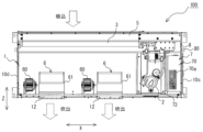
- FIG. 3 is an explanatory diagram showing the internal configuration of the dehumidifier 100 according to the first embodiment, viewed from the top side of the housing 1.
- FIG. 4 is a perspective view of the dehumidifier 100 according to the first embodiment, showing the internal configuration as seen from the back side of the housing 1.
- FIG. 5 is a refrigerant circuit diagram showing a configuration example of the dehumidifier 100 according to the first embodiment.
- the dehumidifier 100 As shown in FIGS. 1 to 4, the dehumidifier 100 according to the first embodiment has an approximately rectangular parallelepiped appearance as a whole, and is installed as a ceiling-mounted type in the ceiling, which is the space to be dehumidified, for example. It is.
- the dehumidifier 100 includes a compressor 2, a condenser 3, an expansion device 4 (see FIG. 5), an evaporator 5, and a blower 6 inside a box-shaped housing 1 that has a substantially rectangular parallelepiped appearance. , a control box 7, and a drain pan 8 are housed therein.
- the dehumidifier 100 has a refrigerant circuit in which a compressor 2, a condenser 3, an expansion device 4, and an evaporator 5 are sequentially connected through piping 9, and in which refrigerant circulates.
- the casing 1 is formed by processing a sheet metal into a substantially rectangular parallelepiped shape, for example.
- the housing 1 has a rectangular front part 10a and a back part 10b formed along the longitudinal direction X, and a front part 10a and a back part 10b formed along the lateral direction Z. It has left and right side portions 10c and 10d that connect, and an upper surface portion 10e and a lower surface portion (not shown).
- a suction port 11 for sucking air from a space to be dehumidified into the interior of the housing 1 is formed in the front portion 10 a of the housing 1 .
- Two air outlets 12 for discharging the air inside the housing 1 to the outside are formed on the back surface 10b of the housing 1 at intervals along the longitudinal direction X. As shown by the white arrows in FIGS. 3 and 4, inside the casing 1, the direction Z from the inlet 11 of the front part 10a to the outlet 12 of the back part 10b is the ventilation direction.
- the evaporator 5 is arranged along the suction port 11 formed in the back surface 10b, and the condenser 3 is arranged downstream of the evaporator 5 in the ventilation direction.
- the compressor 2 is located at a position that does not face the surface of the condenser 3 in the ventilation direction inside the housing 1 in order to avoid downstream air discharged from the condenser 3. It is disposed at a position facing the back surface 10b of the casing 1 away from the condenser 3. This is because the downstream air discharged from the condenser 3 has a high temperature.
- an air blower 6 and a motor 60 that drives the air blower 6 are arranged in the air outlet 12 formed in the back surface portion 10b. In the illustrated example, two blowers 6 and motors 60 are arranged in parallel.
- an opening 13 into which the control box 7 is fitted is formed in one of the left and right side surfaces 10c and 10d.
- the illustrated opening 13 is, for example, a square hole. Note that the opening 13 is not limited to the illustrated square hole, and may have other shapes.
- a support portion 14 is provided inside the housing 1 on which the control box 7 fitted into the opening 13 is placed and supported.
- the support portion 14 may be formed by bending a part of the side surface portion 10c along the opening edge of the opening portion 13, or a support stand made of a separate member from the housing 1 may be provided adjacent to the opening portion 13. It's okay.
- the support part 14 can be implemented in various shapes and sizes as long as it has a configuration that allows the control box 7 fitted in the opening part 13 to be placed and supported.
- the compressor 2 compresses the sucked refrigerant and discharges it in a high temperature and high pressure state.
- the compressor 2 is, for example, a positive displacement compressor that is configured to be able to vary its operating capacity and is driven by a motor that is controlled by an inverter.
- the condenser 3 functions as a reheater in the dehumidifier 100.
- the condenser 3 heats the air by exchanging heat between the high-temperature, high-pressure refrigerant discharged from the compressor 2 and flowing inside the heat transfer tube and the air dehumidified and cooled by the evaporator 5.
- the condenser 3 sucks in air using the blower 6, exchanges heat with the refrigerant, and discharges the air to the outside.
- the condenser 3 is provided with a plurality of fins through which the refrigerant flowing through the heat transfer tubes exchanges heat with air.
- the expansion device 4 depressurizes and expands the refrigerant flowing out from the condenser 3, and is composed of, for example, an electronic expansion valve that can adjust the opening degree of the throttle.
- the opening degree of the expansion device 4 is adjusted by a control device 72 provided inside the control box 7, and the pressure of the refrigerant flowing into the evaporator 5 is controlled.
- the evaporator 5 dehumidifies and cools the air by exchanging heat between the refrigerant flowing out from the expansion device 4 and flowing inside the heat transfer tube and the air sucked in from the space to be dehumidified.
- the evaporator 5 sucks in air using the blower 6, and discharges the air after exchanging heat with the refrigerant to the outside.
- the evaporator 5 is provided with a plurality of fins through which the refrigerant flowing through the heat transfer tubes exchanges heat with the air.
- the blower 6 for example, a centrifugal fan such as a sirocco fan is used.
- the blower 6 generates an airflow in the direction Z from the suction port 11 to the blowout port 12.
- the blower 6 is provided with a suction port 61 on the side surface on which the compressor 2 is disposed.
- the rotation speed of the blower 6 is controlled by the motor 60 being controlled by a control device 72 provided inside the control box 7 .
- the motor 60 is arranged on the side surface opposite to the side surface on which the suction port 61 is provided.
- the drain pan 8 is a container that is placed below the condenser 3 and the evaporator 5 and receives drain water generated from the evaporator 5.
- the bottom surface of the drain pan 8 is inclined from the front side 10a of the casing 1 toward the back side 10b to guide drain water toward the back side 10b of the casing 1. Further, the drain pan 8 is provided with a drain port 80 near the side surface 10c of the housing 1 for draining the accumulated drain water.
- FIG. 6 is an enlarged view of the main parts of the dehumidifier 100 according to the first embodiment, showing a state in which the control box 7 is removed from the opening 13 of the side surface 10c.
- FIG. 7 is a perspective view showing the box body 70 of the control box 7, which is the dehumidifier 100 according to the first embodiment.
- FIG. 8 is an explanatory diagram of the dehumidifier 100 according to the first embodiment, showing how air containing heat generated from the compressor 2 and the control box 7 is sucked in by the blower 6.
- FIG. 9 is an enlarged view of the main parts of the dehumidifier 100 according to the first embodiment, showing a state in which a part of the cover member 71 of the control box 7 is removed from the box body 70 fitted into the opening 13. It is.
- the control box 7 houses therein a control device 72 that controls the entire dehumidifier 100.
- the control box 7 is provided inside the housing 1 on the downstream side of the condenser 3 in the ventilation direction and next to the compressor 2 .
- the control box 7 has a concave box body 70 and a cover member 71 that covers the opening surface of the box body 70.
- a flange portion 70b that projects outward is formed at the opening edge of the box body 70. As shown in FIGS. 6 and 7, the flange portion 70b may be formed along the entire circumference of the opening edge of the box body 70, or may be formed along a part of the opening edge of the box body 70, although not shown. may be formed.
- the control device 72 is configured of, for example, a computer including a memory that stores data and programs necessary for control, and a CPU that executes the programs, dedicated hardware such as ASIC or FPGA, or both.
- the control device 72 controls each part of the entire dehumidifier 100 based on instructions from the remote controller 75. Specifically, the control device 72 controls the drive frequency of the compressor 2, the rotation speed of the blower 6, the opening degree of the expansion device 4, and the like. Further, a power line connected to a local power source is connected to the power terminal. Furthermore, a transmission line that is connected to the compressor 2, blower 6, and expansion device 4 and that transmits command information via the control device 72 is connected to the external input terminal.
- the box 70 is arranged so that the opening face faces the outside of the side surface 10c of the housing 1, and the recess is fitted into the opening 13 formed on the side surface 10c of the housing 1.
- the box 70 fitted into the opening 13 of the housing 1 is placed on the upper surface of the support section 14 provided inside the housing 1.
- the flange portion 70b comes into contact with the side surface portion 10c of the housing 1, and the flange portion 70b is attached to the side surface portion 10c with a joining member such as a screw.
- the box body 70 can be easily removed from the housing 1 by removing the joining member and pulling it out from the opening 13. When the box body 70 is removed, the inside of the housing 1 is opened.
- a worker can perform maintenance work such as replacing refrigerant circuit components installed inside the housing 1, cleaning the drain pan 8, condenser 3, and evaporator 5, and connecting power lines and transmission lines. It can be carried out.
- the dirty portion of the drain pan 8 can be easily cleaned through the opening 13.
- the box 70 is fitted into the opening 13, and the flange portion 70b is attached to the side surface portion 10c with a joining member such as a screw.
- exhaust holes 70a are formed in the upper and lower surfaces of the box body 70 when it is fitted into the interior of the housing 1.
- the exhaust hole 70a is, for example, a plurality of slits.
- the inside can be filled with a dehumidified atmosphere.
- the control box 7 can reduce moisture that causes deterioration or failure of electrical components and boards provided inside.
- the exhaust hole 70a does not necessarily need to be formed on the upper surface and the lower surface, but may be formed on at least the upper surface.
- control box 7 is preferably provided with a heat-resistant member 73 on the side surface of the box body 70 facing the compressor 2. This suppresses the situation in which parts constituting the control device 72 are directly heated through the side surface of the box body 70 by radiant heat generated by the compressor 2, and prevents failure of the control device 72. This is to do so.
- the compressor 2 and the blower 6 are arranged from the position of the control box 7 disposed on one side surface 10c toward the other side surface 10d of the housing 1.
- a control box 7, a compressor 2, and a blower 6 are arranged in this order.
- the blower 6 when the blower 6 is configured to suck air from the side facing the compressor 2 and the control box 7, the blower 6 sucks air containing heat from the compressor 2 and the control box 7. This is because it can be efficiently sucked in by combining with the wind flowing from the condenser 3 and discharged to the outside through the air outlet 12.
- the control box 7 is located further away from the compressor 2 with respect to the blower 6, and the air heated by the compressor 2 is sucked directly into the blower 6 without passing through the control box 7. Air rise inside the control box 7 can be suppressed. Note that, in order to secure an air path, it is desirable that no other member that obstructs the air path be disposed between the blower 6, compressor 2, and control box 7.
- the cover member 71 is a plate-shaped member that closes the opening surface of the box body 70.
- the cover member 71 includes a main cover part 71a that covers the opening surface of the box body 70 from above to near the bottom, and a sub-cover part 71b that covers the lower part of the opening surface of the box body 70.
- the main cover part 71a and the sub cover part 71b are configured to be detachable.
- the main cover portion 71a has a convex portion protruding downwardly formed on the lower edge thereof.
- the sub-cover part 71b is formed with a recessed part that fits into the convex part of the main cover part 71a.
- the cover member 71 is configured such that the convex portion of the main cover portion 71a and the recessed portion of the sub-cover portion 71b fit together, thereby making the main cover portion 71a and the sub-cover portion 71b removable.
- the cover member 71 may have a configuration in which a concave portion is formed along the lower edge of the main cover portion 71a, and a convex portion that fits into the concave portion of the main cover portion 71a is formed in the sub cover portion 71b.
- the cover member 71 is not limited to the above-mentioned uneven shape, but may have other configurations as long as the main cover portion 71a and the sub cover portion 71b are configured to be detachable.
- the sub-cover part 71b is formed with a power line for connecting the local power source and the control device 72, and a wiring hole 71c through which a transmission line from the remote control 75 is passed.
- a wiring hole 71c through which a transmission line from the remote control 75 is passed.
- two wiring holes 71c of different sizes are formed side by side on the left and right in the sub-cover part 71b.
- the control box 7 has a structure in which outside air is taken into the interior through the wiring hole 71c, takes away heat generated from the circuit elements of the control device 72, and discharges the heat into the inside of the casing 1 through the exhaust hole 70a on the top surface. ing.
- the control device 72 housed inside the box body 70 has, for example, a heating element with low heat resistance placed near the wiring hole 71c on the upstream side, and a heating element with low heat resistance placed near the exhaust hole 70a on the downstream side. It is desirable to arrange high heat generating elements. This is to efficiently exhaust the heat inside the control box 7. Further, the position, number, and size of the wiring holes 71c are not limited to the illustrated configuration, but may be changed as appropriate depending on the wiring situation.
- the cover member 71 is attached to the flange portion 70b of the box body 70 with a joining member such as a screw.
- the main cover part 71a and the sub-cover part 71b can be independently attached to the flange part 70b of the box body 70.
- the cover member 71 only the main cover part 71a can be removed from the box body 70, for example, while the sub cover part 71b remains attached to the box body 70. This makes it possible to perform maintenance work on the control device 72 installed inside the control box 7 while it is connected to the power supply line and transmission line, thereby eliminating the need to remove the power supply line and improving work efficiency for the operator. can be improved.
- cover member 71 is not limited to the structure having the main cover part 71a and the sub cover part 71b as illustrated.
- the cover member 71 may be composed of a single piece without providing the main cover part 71a and the sub-cover part 71b separately.
- FIG. 10 is an explanatory diagram showing an example of service spaces (200 to 202) provided around a conventional dehumidifier 300.
- FIG. 11 is an explanatory diagram showing a service space 200 required for maintenance work on the dehumidifier 100 according to the first embodiment.
- the service space 200 when securing a service space around the dehumidifier 300, the service space 200 is provided with an inspection port 200a where the side surface 10c of the housing 1 is located, and the suction port 11 is formed.
- a service space 201 located on the front surface 10a and a service space 202 located on the side surface 10d of the housing 1 are required.
- the service space 201 needs to have a width L1 along the width direction Z of the dehumidifier 300 as a suction space of 300 mm or more.
- the service spaces 200 and 202 need to have a width L2 of 500 mm or more along the longitudinal direction X of the dehumidifier 300.
- an opening 13 into which the control box 7 is fitted is formed in the side surface 10c that connects the front surface 10a and the back surface 10b of the housing 1.
- the control box 7 is fitted into the interior of the housing 1 through the opening 13 of the housing 1, and is attached to the side surface 10c of the housing 1 so that the opening 13 can be opened and closed.
- the dehumidifier 100 by removing the control box 7 from the housing 1 and opening the opening 13, the refrigerant circuit components installed inside the housing 1 can be cooled through the opening 13. Maintenance work such as replacement, cleaning of the drain pan 8, condenser 3 and evaporator 5, and connection of power lines and transmission lines can be performed. Therefore, as shown in FIG. 11, it is only necessary to provide a service space 200 near the side surface 10c in which the opening 13 into which the control box 7 is fitted is formed. Therefore, even if the dehumidifier 100 is installed in the attic, which is a narrow space, the maintenance work can be easily performed in the attic without securing a sufficient service space necessary for the operator's work. can. Furthermore, since there is no need to secure a sufficient service space, the service space that has been required up to now can be reduced, and the choice of installation location for the dehumidifier 100 is increased, such as in the ceiling where installation locations are restricted.
- a support portion 14 is provided inside the housing 1 on which the control box 7 fitted into the opening 13 is placed and supported. Therefore, in the dehumidifier 100 according to the first embodiment, the control box 7 can be easily fitted into the opening 13, and the control box 7 can be stably installed inside the housing 1.
- control box 7 includes a concave box body 70 and a cover member 71 that closes the opening surface of the box body 70.
- a flange portion 70b that projects outward is formed at the opening edge of the box body 70.
- the control box 7 has a structure in which a box body 70 is fitted into the opening 13 of the casing 1, and a flange portion 70b is attached to the side surface 10c of the casing 1. Therefore, in the dehumidifier 100 according to the first embodiment, the control box 7 can be firmly fixed to the housing 1 and installed.
- the cover member 71 has a main cover part 71a and a sub-cover part 71b that is detachably attached to the main cover part 71a.
- the cover member 71 is configured such that the main cover part 71a can be attached to and removed from the box body 70 while the sub cover part 71b is attached to the box body 70.
- a wiring hole 71c is formed in the sub-cover part 71b, through which a power line, etc. for connecting the local power source and the control device 72 is passed, it is possible to insert the wiring hole 71c inside the control box 7 with the power line etc. connected. Maintenance work can be performed on the installed control device 72. Therefore, the trouble of removing the power supply wire etc. is omitted, and the work efficiency of the worker can be improved.
- a heat-resistant member 73 is provided on the side surface of the control box 7 facing the compressor 2. This prevents the parts constituting the control device 72 from being directly heated through the side surface of the box body 70 by radiant heat generated from the compressor 2, and prevents the control device 72 from malfunctioning. This can be prevented.
- control box 7 has an exhaust hole 70a formed on the upper surface thereof when it is fitted into the housing 1.
- the control box 7 is disposed inside the housing 1 on the downstream side of the condenser 3 in the ventilation direction. Therefore, the interior of the control box 7 can be filled with a dehumidified atmosphere, thereby reducing moisture that causes deterioration or failure of electrical components and boards provided inside.
- the housing 1 when the housing 1 is viewed from the top side, there are a position where the exhaust hole 70a of the control box 7 is formed, a position where the compressor 2 is installed, and a suction port of the blower 6.
- the control box 7, the compressor 2, and the blower 6 are arranged so that the position where the control box 61 is formed is on a straight line.
- the blower 6 when the blower 6 is configured to draw in air from the side facing the compressor 2 and the control box 7, the blower 6 absorbs the air containing the heat of the compressor 2 and the control box 7 into the air flowing from the condenser 3. It can be efficiently sucked in by merging with the air and discharged to the outside through the air outlet 12.
- the control box 7 has a configuration in which outside air is taken into the interior through the wiring hole 71c and heat is exhausted to the outside through the exhaust hole 70a. Thereby, the heat inside the control box 7 can be efficiently discharged.
- the compressor 2 and the blower 6 are arranged from the position of the control box 7 disposed on one side surface 10c toward the other side surface 10d of the housing 1. 2.
- the blower 6 is arranged in this order. As a result, when the blower 6 is configured to draw in air from the side facing the compressor 2 and the control box 7, the blower 6 absorbs the air containing the heat of the compressor 2 and the control box 7 into the air flowing from the condenser 3. It can be efficiently sucked in by merging with the air and discharged to the outside through the air outlet 12.
- the compressor 2 is arranged at a position that does not face the surface of the condenser 3 in the ventilation direction inside the casing 1. As a result, the compressor 2 can be placed in a position away from the air discharged from the condenser 3 on the downstream side, where the temperature is high, so that an increase in the temperature of the compressor 2 can be suppressed.
- FIG. 12 is a perspective view of the appearance of the dehumidifier 101 according to the second embodiment as viewed from the front side of the housing 1, with the opening 13 of the side surface 10c open.
- FIG. 13 is an explanatory diagram showing the internal configuration of the dehumidifier 101 according to the second embodiment, viewed from the top side of the housing 1.
- FIG. 14 is a perspective view showing the external appearance of the dehumidifier 101 according to the second embodiment when viewed from the front side of the housing 1, and showing a different state in which the opening 13 of the side surface 10c is open.
- FIG. 12 is a perspective view of the appearance of the dehumidifier 101 according to the second embodiment as viewed from the front side of the housing 1, with the opening 13 of the side surface 10c open.
- FIG. 14 is a perspective view showing the external appearance of the dehumidifier 101 according to the second embodiment when viewed from the front side of the housing 1, and showing a different state in which the opening 13 of the side surface 10c is open.
- FIG. 15 is an enlarged view of main parts showing a first modification of the dehumidifier 101 according to the second embodiment.
- FIG. 16 is a side view showing a second modification of the dehumidifier 101 according to the second embodiment.
- 12 to 15 show a state in which the cover member 71 is removed from the box body 70. Note that the same components as those of the dehumidifier 100 described in Embodiment 1 are given the same reference numerals, and the description thereof will be omitted as appropriate.
- an opening into which the control box 7 is fitted is provided in the side surface 10c connecting the front surface 10a and the rear surface 10b. 13 are formed.
- the control box 7 is fitted into the interior of the housing 1 through the opening 13 of the housing 1, and is attached to the side surface 10c of the housing 1 so that the opening 13 can be opened and closed.
- a box body 70 is fitted into an opening 13 of a housing 1, and a flange portion 70b is joined to a side surface portion 10c of the housing 1 via a hinge mechanism portion 74. It is attached with parts.
- the box body 70 is configured such that the opening 13 of the housing 1 can be opened and closed with a portion of the side surface 10 c of the housing 1 being joined to a hinge mechanism 74 .
- 13 and 14 of the flange parts 70b formed around the box body 70, the flange parts 70b located on the front side and the back side of the housing 1 are attached via a hinge mechanism part 74.
- the other flange portion 70b is attached to the side surface portion 10c of the housing 1 using a joining member.
- the opening 13 of the housing 1 When opening the opening 13 of the housing 1, after removing the cover member 71 from the box 70, as shown in FIGS. The other joining members of the flange portion 70b are removed, leaving the remaining members. By doing so, the opening 13 of the casing 1 can be opened in a half-open state via the hinge mechanism 74 while the box 70 is attached to the side surface 10c of the casing 1.
- the opening 13 of the casing 1 when the opening 13 of the casing 1 is opened, the cover member 71 is removed from the box 70, and then the opening 13 of the casing 1 is opened.
- the joining member of the flange portion 70b located on the back side may be left, and the joining members of the other flange portion 70b may be removed.
- the opening 13 of the casing 1 can be opened in a half-open state via the hinge mechanism 74 while the box 70 is attached to the side surface 10c of the casing 1.
- the dehumidifier 101 has only the flange portion 70b located on the back side of the housing 1 among the flange portions 70b formed around the box body 70. They may be joined via the hinge mechanism section 74. Although not shown, only the flange portion 70b located on the front side of the housing 1 among the flange portions 70b formed around the box body 70 may be joined via the hinge mechanism portion 74. good. Even in this case, the opening 13 of the casing 1 can be opened in a half-open state via the hinge mechanism 74 while the box 70 is attached to the side surface 10c of the casing 1.
- a hinge mechanism part 74 is attached to the side surface 10c of the housing 1 together with the cover member 71. It may also be attached with a joining member via. By doing this, the opening 13 of the housing 1 can be opened via the hinge mechanism 74 while the control box 7 is attached to the side surface 10c of the housing 1 without removing the cover member 71 from the housing 70. It can be opened in a half-open state. Also in this case, of the flange portions 70b formed around the box body 70, only the flange portions 70b located on the front side or the back side of the housing 1 may be joined via the hinge mechanism portion 74. good.
- the cover member 71 shown in FIG. 16 is composed of one sheet, it may have a structure having a main cover part 71a and a sub-cover part 71b, as shown in FIGS. 1 and 6.
- control box 7 is partially joined to the hinge mechanism 74 on the side surface 10c of the housing 1, and the control box 7 is connected to the opening 13 of the housing 1. Since the control box 7 is configured to be openable and closable, there is no need to remove the control box 7, and there is no need to worry about where to put the removed control box 7, so the workability of maintenance work can be improved.
- the dehumidifiers 100 and 101 have been described above based on the embodiments, the dehumidifiers 100 and 101 are not limited to the configurations of the embodiments described above.
- the configurations of the dehumidifiers 100 and 101 described above are merely examples, and may include other components or may omit some components.
- the dehumidifiers 100 and 101 are not limited to a configuration in which they are installed as ceiling-mounted types in the ceiling which is the space to be dehumidified, but may be installed in a place other than the ceiling.
- the housing 1 is not limited to the illustrated rectangular parallelepiped shape, but may have other shapes. In short, the dehumidifiers 100 and 101 are subject to a range of design changes and application variations that are commonly made by those skilled in the art without departing from the technical concept thereof.
Landscapes
- Chemical & Material Sciences (AREA)
- Engineering & Computer Science (AREA)
- Analytical Chemistry (AREA)
- General Chemical & Material Sciences (AREA)
- Oil, Petroleum & Natural Gas (AREA)
- Chemical Kinetics & Catalysis (AREA)
- Drying Of Gases (AREA)
Priority Applications (2)
| Application Number | Priority Date | Filing Date | Title |
|---|---|---|---|
| JP2024526032A JPWO2023238183A1 (https=) | 2022-06-06 | 2022-06-06 | |
| PCT/JP2022/022765 WO2023238183A1 (ja) | 2022-06-06 | 2022-06-06 | 除湿機 |
Applications Claiming Priority (1)
| Application Number | Priority Date | Filing Date | Title |
|---|---|---|---|
| PCT/JP2022/022765 WO2023238183A1 (ja) | 2022-06-06 | 2022-06-06 | 除湿機 |
Publications (1)
| Publication Number | Publication Date |
|---|---|
| WO2023238183A1 true WO2023238183A1 (ja) | 2023-12-14 |
Family
ID=89117918
Family Applications (1)
| Application Number | Title | Priority Date | Filing Date |
|---|---|---|---|
| PCT/JP2022/022765 Ceased WO2023238183A1 (ja) | 2022-06-06 | 2022-06-06 | 除湿機 |
Country Status (2)
| Country | Link |
|---|---|
| JP (1) | JPWO2023238183A1 (https=) |
| WO (1) | WO2023238183A1 (https=) |
Citations (5)
| Publication number | Priority date | Publication date | Assignee | Title |
|---|---|---|---|---|
| JP2001153547A (ja) * | 1999-11-26 | 2001-06-08 | Bridgestone Corp | バスル−ムの乾燥システム |
| JP2004293987A (ja) * | 2003-03-27 | 2004-10-21 | Toto Ltd | 脱衣室冷房装置 |
| JP2005254110A (ja) * | 2004-03-10 | 2005-09-22 | Cosmo Denki Kk | 除湿装置 |
| WO2013129527A1 (ja) * | 2012-02-29 | 2013-09-06 | 東芝キヤリア株式会社 | ビルトイン型空気調和機 |
| JP2018141593A (ja) * | 2017-02-28 | 2018-09-13 | 株式会社日立空調Se | 空気調和機 |
Family Cites Families (3)
| Publication number | Priority date | Publication date | Assignee | Title |
|---|---|---|---|---|
| JP4789548B2 (ja) * | 2005-08-29 | 2011-10-12 | 三洋電機株式会社 | 空気調和装置 |
| CN211011674U (zh) * | 2019-11-19 | 2020-07-14 | 珠海市威诺环境技术设备有限公司 | 一种除湿机的驱动散热结构 |
| CN214791589U (zh) * | 2021-04-19 | 2021-11-19 | 杭州弘泰电器有限公司 | 一种吊顶除湿机 |
-
2022
- 2022-06-06 JP JP2024526032A patent/JPWO2023238183A1/ja active Pending
- 2022-06-06 WO PCT/JP2022/022765 patent/WO2023238183A1/ja not_active Ceased
Patent Citations (5)
| Publication number | Priority date | Publication date | Assignee | Title |
|---|---|---|---|---|
| JP2001153547A (ja) * | 1999-11-26 | 2001-06-08 | Bridgestone Corp | バスル−ムの乾燥システム |
| JP2004293987A (ja) * | 2003-03-27 | 2004-10-21 | Toto Ltd | 脱衣室冷房装置 |
| JP2005254110A (ja) * | 2004-03-10 | 2005-09-22 | Cosmo Denki Kk | 除湿装置 |
| WO2013129527A1 (ja) * | 2012-02-29 | 2013-09-06 | 東芝キヤリア株式会社 | ビルトイン型空気調和機 |
| JP2018141593A (ja) * | 2017-02-28 | 2018-09-13 | 株式会社日立空調Se | 空気調和機 |
Also Published As
| Publication number | Publication date |
|---|---|
| JPWO2023238183A1 (https=) | 2023-12-14 |
Similar Documents
| Publication | Publication Date | Title |
|---|---|---|
| JP5079138B2 (ja) | 熱交換換気装置 | |
| CN101896774B (zh) | 空调装置的室内机组 | |
| JP2023071327A (ja) | 室内機 | |
| JP5449950B2 (ja) | 外気処理空気調和機 | |
| JP3159654B2 (ja) | 空気調和機 | |
| WO2023238183A1 (ja) | 除湿機 | |
| JP6507870B2 (ja) | ダクト型空気調和機の室内機 | |
| JP6313160B2 (ja) | 床置き型空気調和装置 | |
| CN206890670U (zh) | 空调机的室内机 | |
| US20070227172A1 (en) | Air Conditioner | |
| JP4436787B2 (ja) | 空気調和機 | |
| CN219976581U (zh) | 风管机 | |
| CN100340817C (zh) | 换气装置 | |
| JPH0641073Y2 (ja) | 熱交換器付換気装置 | |
| JP4560967B2 (ja) | 空気調和装置 | |
| JPH0636421Y2 (ja) | 空気調和機 | |
| WO2021171348A1 (ja) | 空気調和装置 | |
| JP2010117104A (ja) | 空調機 | |
| JP2005083654A (ja) | 空気調和機 | |
| JPWO2019043986A1 (ja) | 空気調和機の室内機 | |
| KR100347947B1 (ko) | 공기조화기의 토출구 구조 | |
| KR101028950B1 (ko) | 환기장치 | |
| JP2012154541A (ja) | 空気調和機 | |
| JP2000249362A (ja) | ビルトイン型空気調和機 | |
| JPH1047724A (ja) | 熱交換換気装置 |
Legal Events
| Date | Code | Title | Description |
|---|---|---|---|
| 121 | Ep: the epo has been informed by wipo that ep was designated in this application |
Ref document number: 22945693 Country of ref document: EP Kind code of ref document: A1 |
|
| WWE | Wipo information: entry into national phase |
Ref document number: 2024526032 Country of ref document: JP |
|
| NENP | Non-entry into the national phase |
Ref country code: DE |
|
| 122 | Ep: pct application non-entry in european phase |
Ref document number: 22945693 Country of ref document: EP Kind code of ref document: A1 |